
Ancillary piping components are the additional items installed in a piping system such as pumps, heat exchangers, valves and instrumentation. Their requirements vary depending on the media being transported in the piping system. Module 3 unit 2 has dealt with pumps, valves and basic instrumentation so this module will examine the different type of common heat exchangers and evaluate different pumps against specific pump selection criteria.
A heat exchanger is a device built for efficient heat transfer from one medium to another. The heating or cooling media is separated from the product to be heated or cooled by a solid wall, so that they never mix. There are three primary classifications of heat exchangers according to their flow arrangement. In parallel-flow heat exchangers, the two fluids enter the exchanger at the same end, and travel in parallel to one another to the other side. In counter-flow heat exchangers the fluids enter the exchanger from opposite ends. In a cross-flow heat exchanger, the fluids travel roughly perpendicular to one another through the exchanger. The counter current design is most efficient, in that it can transfer the most heat from the heat (transfer) medium. For efficiency, heat exchangers are designed to maximize the surface area of the wall between the two fluids, while minimizing resistance to fluid flow through the exchanger. The exchanger's performance can also be affected by the addition of fins or corrugations in one or both directions, which increase surface area and may channel fluid flow or induce turbulence. We will deal the 2 most common types of heat exchangers:
Shell and tube heat exchangers consist of a series of tubes (see Figure 1). One set of these tubes contains the fluid that must be either heated or cooled. The second fluid runs over the tubes that are being heated or cooled so that it can either provide the heat or absorb the heat required. A set of tubes is called the tube bundle and can be made up of several types of tubes: plain, longitudinally finned, etc. Shell and Tube heat exchangers are typically used for high pressure applications (with pressures greater than 30 bar and temperatures greater than 260°C). This is because the shell and tube heat exchangers are robust due to their shape.
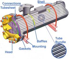
Figure 1 – Component parts of a shell and tube heat exchanger
There are several thermal design features that are to be taken into account when designing the tubes in the shell and tube heat exchangers. These include:

Figure 2 – Tube bundle with baffle plates
A plate heat exchanger is composed of multiple, thin, slightly-separated plates that have very large surface areas and fluid flow passages in between for heat transfer.
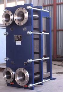
Figure 3 – Plate and frame heat exchanger with media connections on head plate
Plate heat exchangers can differ in the types of plates that are used, and in the configurations of those plates. Some plates may be formed with "chevron" (Figure 4a) or other patterns to increase flow turbulence and therefore heat transfer, where others may have machined fins and/or grooves. The gasket design (Figure 4a) allows the heating or cooling medium to flow through every second space in the plate stack and the product medium to be heated or cooled flows through the alternate spaces as can be seen in Figure 4b.
Figure 4a – Chevron plate to improve heat transfer, gasket design to direct flow
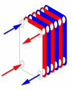
Figure 4b - Counter current flow in alternate fluid spaces
While shell and tube heat exchangers are more suited to high pressure applications plate and frame heat exchangers have the following advantages:
Pumps transfer liquids from one point to another by converting mechanical energy into pressure energy (head). The pressure applied to the liquid forces the fluid to flow at the required rate and to overcome friction (or head) losses in piping, valves, fittings, and process equipment. Pumping applications include constant or variable flow rate requirements, serving single or networked loads, and consisting of open loops (liquid delivery) or closed loops (recirculation systems). When selecting a pump the following points should be considered:
The pumping system designer must consider fluid properties, determine end use requirements, and understand environmental conditions.
Once these and perhaps other site-specific factors are known, it is possible to consult manufacturers’ literature and consider the available pumps. A major portion of this process involves consideration of trade-offs among the reliability, first cost, and operation and maintenance cost of various pumps having suitable flow/head/efficiency characteristics. Table 1 below highlights the advantages relative to each other of the following 3 pumps and why they would be selected for a particular duty:
Pump Characteristic |
Centrifugal |
Diaphragm |
Drum |
Flow Rate |
High |
Medium |
Low |
NPSH |
Needs a positive head |
Can suck liquid into pump from below |
Can suck liquid into pump from below |
Pressure |
Normally low |
Medium |
High |
Viscosity/ solids content |
Low |
High |
Medium |
Power supply |
Electrical |
Compressed Air |
Electrical or Compressed air |
Location |
Supplier dependant |
Supplier dependant |
Supplier dependant |
Maintenance |
Low |
Medium |
Medium |
Table 1 – Comparison of pump characteristics for pump selection
First the basis of design is established, the equipment and materials of construction selected and the Process Flow Diagram (PFD) agreed for a process piping system. The next step is to move on to a more detailed design of the system. The P&ID provides a schematic layout of the equipment, valves, instrumentation and line sizes. It is however not drawn to scale and only present the relationship or sequence between components and how they interact to control the systems functions.
The physical layout of the major items of equipment, valves and instrumentation is vital to the ergonomic operation of the plant long after the construction phase is complete. The interconnection pipework and bracketing of same is also critical to facilitate ease of access and future maintenance of the system. While this list is not exhaustive the following points should be considered when finalizing equipment and piping layouts:
The layout of equipment and pipe routing is greatly aided by the use of 3D modeling software (see Figure 5a and 5b) which allows piping designers to visualize the complete installation and zoom in on congested areas to check for clashes of valves and instrumentation. Extensive component libraries allow the designer to quickly import standard components to compile the system model which can then perform static and dynamic stress analyses on pipe and equipment and indicate the best positions for anchors and supports. Individual isometrics can be exported with bills of materials for purchasing to procure the necessary materials and the more sophisticated packages can be linked with ERP systems to provide a complete costing tool.
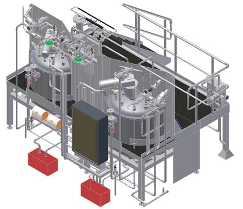
Figure 5a – 3D model of equipment and pipe layout for pharmaceutical process system
Figure 5b – Close up of 3D model for pipes valves and instruments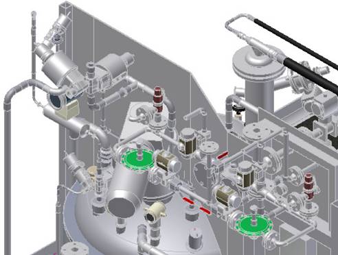
For liquid piping systems, valves are the controlling element. Valves are used to isolate equipment and piping systems, regulate flow, prevent backflow, and regulate and relieve pressure. The most suitable valve must be carefully selected for the piping system. The minimum design or selection parameters for the valve most suitable for an application are the following: size, material of construction, pressure and temperature ratings, and end connections. In addition, if the valve is to be used for control purposes, additional parameters must be defined. These parameters include: method of operation, maximum and minimum flow capacity requirement, pressure drop during normal flowing conditions, pressure drop at shutoff, and maximum and minimum inlet pressure at the valve. These parameters are met by selecting body styles, material of construction, seats, packing, end connections, operators and supports.
While construction schedule and costs drive mechanical contractors to install piping systems quickly it must be remembered that the final system will be operated for many years in the future. For this reason it is critical that proper consideration be given to the ergonomic layout of the equipment and instrumentation so as to ensure that the operator can comfortably operate the system. Simple things such as gauges at an ergonomic height, orientated in an upright position and with readable sized scales can make the monitoring and recording of information so much easier. Ease of access to equipment for periodic inspections and checking for leaks will ensure that the plant is well cared for and well maintained. Space for removing equipment
Isolation Valves
Check valve
Pump
Strainer
Process commissioning occurs between the time construction is complete and plant startup commences. During this period process commissioning personnel are occupied with the task of ensuring the facilities have been constructed and assembled according to the engineering design and the equipment manufacturer’s directions. The objective is to ensure that the equipment has been properly installed and is ready to receive process materials and operate as originally conceived.
While this list is not exhaustive the following points should be considered when preparing for safe start-up and commissioning of ancillary piping equipment:
Just as with the actual construction of the process facility, process commissioning is a complex activity covering all aspects of the newly constructed facilities.
Coordination between trades is essential and tasks such as the following will need two or more trades to verify:
Should problems develop during the startup phase, written plans and procedures should be in place to empty each process unit in a safe and environmentally compliant manner so that whatever problems occurred can be fixed. Any defects found during he commissioning process must be corrected by the contractor before the process unit commissioning can be declared as complete.
A major part of process commissioning is in preparing the operating instructions for the startup of the process. The procedures for a newly constructed plant often differ from the procedures that would be placed in service after a successful production campaign. In the case of a newly constructed plant, the procedure may call for each upstream unit to be brought up to operating temperatures and pressure and held for a period of time to validate the integrity of the unit before process material is allowed to flow to the next downstream unit.
More and more industries have placed an increasing emphasis on quality standards and documentation in order to expedite their approval process for either their own internal corporate quality requirements or for external bodies such as the IMB (Irish Medicines Board) or the FDA (United States Food and Drug Administration). The approval process requires that the facility in which a new product or drug is produced must be designed, constructed and commissioned so that it meets the criteria for process validation.
Validation is the action of proving, in accordance with the principles of GMP (Good Manufacturing Practice), that any procedure, process, equipment, material activity or system consistently leads to the expected results. Documented evidence provides a high degree of assurance that a specific system, equipment or process will consistently produce a product meeting its pre-determined specifications and quality attributes. To put it simply, validation is nothing more than proving that a process actually works.
Failure to achieve validation on the first attempt can be very costly to the facility owner, so maintaining quality from the design phase throughout the construction process is essential. To this end the pipe fitter / welder can play a major part in ensuring the following documents are maintained and collated in a controlled fashion:
Title |
Author |
Ref. Code |
The Induction Book, “Code of Behaviour & Health & Safety Guidelines” |
SOLAS |
|
Basic Welding and Fabrication |
W Kenyon |
ISBN 0-582-00536-L |
Fundamentals of Fabrication and Welding Engineering |
FJM Smith |
ISBN 0-582-09799-1 |
Workshop processes, practices and materials, 3rd edition, Elsevier Science & Technology |
Black, Bruce J 2004 |
ISBN-13: 9780750660730 |
New Engineering Technology |
Lawrence Smyth & Liam Hennessy |
ISBN 086 1674480 |
Source: http://local.ecollege.ie/Content/APPRENTICE/liu/pipefitting/word/M4_U5_Ancillary%20Piping%20Equipment.doc
Web site to visit: http://local.ecollege.ie/
Author of the text: indicated on the source document of the above text
If you are the author of the text above and you not agree to share your knowledge for teaching, research, scholarship (for fair use as indicated in the United States copyrigh low) please send us an e-mail and we will remove your text quickly. Fair use is a limitation and exception to the exclusive right granted by copyright law to the author of a creative work. In United States copyright law, fair use is a doctrine that permits limited use of copyrighted material without acquiring permission from the rights holders. Examples of fair use include commentary, search engines, criticism, news reporting, research, teaching, library archiving and scholarship. It provides for the legal, unlicensed citation or incorporation of copyrighted material in another author's work under a four-factor balancing test. (source: http://en.wikipedia.org/wiki/Fair_use)
The information of medicine and health contained in the site are of a general nature and purpose which is purely informative and for this reason may not replace in any case, the council of a doctor or a qualified entity legally to the profession.
The texts are the property of their respective authors and we thank them for giving us the opportunity to share for free to students, teachers and users of the Web their texts will used only for illustrative educational and scientific purposes only.
All the information in our site are given for nonprofit educational purposes