
References:
[a] NAVAIR 00-80T-80, Aerodynamics for Naval Aviators
[b] NAVEDTRA 14014, Airman
[c] NAVAIR 00-80T-88, Helicopter History and Aerodynamics Manual
[d] NAVEDTRA 12300, Aviation Machinist’s Mate 3&2
[e] NAVEDTRA 14176, NEETS Module 4--Introduction to Electrical Conductors, Wiring Techniques, and Schematic Reading
[f] NAVEDTRA 14313, Aviation Ordnanceman
[g] NAVEDTRA 14175, NEETS Module 3--Introduction to Circuit Protection, Control, and Measurement
[h] NAVEDTRA 14188, NEETS Module 16--Introduction to Test Equipment
[i] NAVEDTRA 14028, Aviation Electronics Technician 3
[j] NAVEDTRA 14192, NEETS Module 20--Master Glossary and Index
[k] http://www.chinfo.navy.mil/navpalib/factfile/ffiletop.html
[l] NAVAIR 00-80T-105, CV NATOPS Manual
[m] NAVAIR 00-80T-96, Common Support Equipment Basic Handling and Safety Manual
[n] NAVAIR 00-80T-106, LHA/LHD/MCS NATOPS Manual
[o] NAVAIR 00-80T-120, CV Flight/Hangar Deck NATOPS Manual
[p] OPNAVINST 5100.19D, Navy Occupational Safety and Health (NAVOSH) Program Manual for Forces Afloat
[q] Local Directives and Standard Operating Procedures
[r] NAVAIR 00-80T-113, Aircraft Signals NATOPS Manual
[s] NAVAIR 00-80R-14, NATOPS U.S. Navy Aircraft Firefighting and Rescue Manual
[t] NAVEDTRA 14353, Aviation Boatswains Mate (H)
[u] NAVAIR 19-25-514, Firefighting Vehicle A/S32P-25
[v] NAVEDTRA 14208, Photography (Advanced)
[w] NAVEDTRA 14127, Intelligence Specialist 3&2, Vol. 1
[x] NAVAIR 01-Fl4AAA-1, F-14 NATOPS
[y] NAVEDTRA 14312, Aerographer's Mate Module 5 - Basic Meteorology
[z] NAVEDTRA 14269, Aerographer’s Mate Module 1 - Surface Weather Observations
[aa] NAVEDTRA 14010, Aerographer’s Mate 1&C
[ab] OPNAVINST 3120.32C, Standard Organization and Regulations Manual of the U.S. Navy (SORM)
1 Explain the following expressions of motion: [ref. a]
a. Potential energy: (Stored Energy) The energy stored in a body or system; the energy that a body or system has stored because of its position in an electric, magnetic, or gravitational field, or because of its configuration.
b. Kinetic energy: (Energy in Motion) The kinetic energy of an object is the extra energy which it possesses due to its motion. It is defined as the work needed to accelerate a body of a given mass from rest to its current velocity. Having gained this energy during its acceleration, the body maintains this kinetic energy unless its speed changes.
.2 Describe the following terms pertaining to motion: [ref. b, ch. 3]
a. Inertia: The tendency of a body at rest to remain at rest, and a body in motion to continue to move at a constant speed along a straight line, unless the body is acted upon in either case by an unbalanced force.
b. Acceleration: A change in the velocity of a body, or the rate of such change with respect to speed or direction.
c. Speed: The rate of movement or motion in a given amount of time. Speed is the term used when only the rate of movement is meant. If the rate of movement of a ship is 14 knots, we say its speed is 14 knots per hour.
d. Velocity: The quickness or speed of an object in a given time and direction. For example: 200 mph due north.
.3 Define Bernoulli's principle. [ref. b, ch. 3]
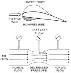 * The principle states that when a fluid flowing through a tube reaches a constriction or narrowing of the tube, the speed of the fluid passing through the constriction is increased and its pressure decreased. The general lift of an airfoil is dependent upon the airfoil's being able to create circulation in the air stream and develop the lifting pressure over the airfoil surface. As the relative wind strikes the leading edge of the airfoil, the flow of air is split. Part is deflected upward and aft, and the rest is deflected down and aft. Since the upper surface of the wing has camber or a curve on it, the flow over its surface is disrupted, and this causes a wavelike effect to the wing. The lower surface is relatively flat. Lift is accomplished by the difference in the airflow across the airfoil.
.4 Define Boyle’s law. [ref. b, ch. 3]
* States that when the temperature is held constant, the volume of a gas is inversely proportional to its pressure. Therefore, if the pressure increases, the volume decreases and visa versa. For example, if the volume if halved, then the pressure is doubled. If the temperature is held constant, it becomes an isothermal process. Discovered by Robert Boyle (1627-1691), an Irish physicist and chemist and co-founder of the Royal Society
.5 Describe the following properties of the atmosphere as it relates to aircraft performance: [ref. a]
a. Static pressure: The static pressure of the air at any altitude results from the mass of air supported above that level. At standard sea level conditions the static pressure of the air is 2,116 psf (or 14.7 psi, 29.92 in. Hg, etc.) and at 40,000 feet altitude this static pressure decreases to approximately 19 percent of the sea level value.
b. Absolute temperature: The ordinary temperature measurement by the
Centigrade scale has a/datum at the freezing point of water but absolute zero temperature is obtained at a temperature of -273“ Centigrade. Thus, the standard sea level temperature of 15” C. is an absolute temperature of 288”. This scale of absolute temperature using the Centigrade increments is the Kelvin scale, e.g., o K.
c. Density: The density of the air is a property of greatest importance in the study of aerodynamics. The density of air is simply the mass of air per cubic foot of volume and is a direct measure of the quantity of matter in each cubic foot of air. Air at standard sea level conditions weighs 0.0765 pounds per cubic foot and has a density of 0.002378 slugs per cubic foot. At an altitude of 40,000 feet the air density is approximately 25 percent of the sea level value.
d. Viscosity: The viscosity of the air is important in scale and friction effects. The coefficient of absolute viscosity is the proportion between the shearing stress and velocity gradient for a fluid flow. The viscosity of gases is unusual in that the viscosity is generally a function of temperature alone and an increase in temperature increases the viscosity.
e. Standard atmosphere: The standard atmosphere actually represents the mean or average properties of the atmosphere. Notice that the lapse rate is constant in the troposphere and the stratosphere begins with the isothermal region. Since all aircraft performance is compared and evaluated in the environment of the standard atmosphere, all of the aircraft instrumentation is calibrated for the standard atmosphere.
f. Pressure altitude: Pressure altitude is the altitude in the standard atmosphere corresponding to a particular pressure. The aircraft altimeter is essentially a sensitive barometer calibrated to indicate altitude in the standard atmosphere. If the altimeter is set for 29.92 in. Hg the altitude indicated is the pressure altitude-the altitude in the standard atmosphere corresponding to the sensed pressure. Of course, this indicated pressure altitude may not be the actual height above sea level due to variations in temperature, lapse rate; atmospheric pressure, and possible errors in the sensed pressure.
g. Density altitude: The more appropriate term for correlating aerodynamic performance in the nonstandard atmosphere is density altitude in the standard atmosphere corresponding to a particular value of air density. The computation of density altitude must certainly involve consideration of pressure (pressure altitude) and temperature.
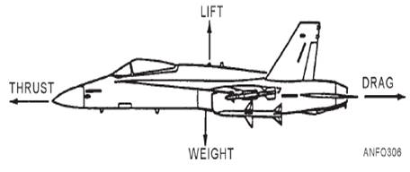
.6 Describe the following aerodynamic terms and their interrelationships: [ref. b, ch. 3]
a. Lift: The force that acts, in an upward direction, to support the aircraft in the air. It counteracts the effects of weight. Lift must be greater than or equal to weight if flight is to be sustained.
b. Weight: The force of gravity acting downward on the aircraft and everything on the aircraft
c. Drag: The force that tends to hold an aircraft back. Drag is caused by the disruption of the air about the wings, fuselage or body, and all protruding objects on the aircraft. Drag resists motion.
d. Thrust: The force developed by the aircraft's engine, and it acts in the forward direction. Thrust must be greater than or equal to the effects of drag in order for flight to begin or be sustained
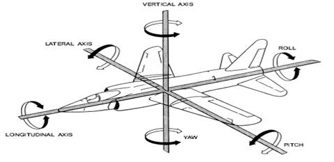
e. Longitudinal axis: An imaginary reference line running down the center of the aircraft between the nose and tail. The axis about which roll occurs.
f. Vertical axis: An imaginary reference line running parallel to the wings and about which pitch occurs
g. Lateral axis: An imaginary reference line running from the top to the bottom of the aircraft. The movement associated with this axis is yaw.
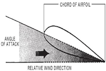 h. Angle of attack: The angle at which a body, such as an airfoil or fuselage, meets a flow of air. Defined as the angle between the chord line of the wing (an imaginary straight line from the leading edge to the trailing edge of the wing) and the relative wind. The relative wind is the direction of the air stream in relationship to the wing. For example, an aircraft in straight and level flight has the relative wind directly in front of it and has zero angle of attack since the relative wind is directly striking the leading edge of the wing. An aircraft flying parallel to the ground which has the nose trimmed significantly up, now has the leading edge of the wing (chord line) pointed at an upward angle; however, the relative wind is striking the bottom of the wing. An analogy is to hold your hand out of the car window with your palm facing the ground (zero angle of attack), and then to rotate your hand slightly in either direction. Angle of attack is measured in "units" as opposed to degrees.
 .7 State the three primary movements of aircraft about the axis. [ref. b, ch. 3]
a. Pitch - The movement of the aircraft about its lateral axis. The up and down motion of the nose of the aircraft.
b. Yaw - The movement of the aircraft about its vertical axis. The drift, or right or left movement of the nose of the aircraft.
c. Roll - The movement of the aircraft about its longitudinal axis. The movement of the wing tips one up and the other down.
.8 State the purpose of the following flight control surfaces: [ref. b, ch. 4]
a. Flap: Gives the aircraft extra lift. The purpose is to reduce the landing speed, thereby shortening the length of the landing rollout. They also facilitate landing in small or obstructed areas by permitting the gliding angle to be increased without greatly increasing the approach. The use of flaps during takeoff serves to reduce the length of the takeoff run. Some flaps are hinged to the lower trailing edges of the wings inboard of the ailerons. Leading edge flaps are in use on the Navy F-4, Phantom II.
b. Spoiler: Used to decrease wing lift. However, the specific design, function, and use vary with different aircraft. On some aircraft, the spoilers are long narrow surfaces, hinged at their leading edge to the upper surfaces of the wings. In the retracted position, they are flush with the wing skin. In the raised position, they greatly reduce wing lift by destroying the smooth flow of air over the wing surfaces
c. Speed brakes: Hinged or moveable control surfaces used for reducing the speed of aircraft. On some aircraft, they are hinged to the sides or bottom of the fuselage; on others they are attached to the wings. They keep the speed from building too high in dives. They are also used to slow the speed of the aircraft prior to landing.
d. Slats: Slats are movable control surfaces attached to the leading edge of the wing. When the slat is retracted, it forms the leading edge of the wing. When open, or extended forward, a slot is created between the slat and the wing leading edge. High-energy air is introduced into the boundary layer over the top of the wing. At low airspeeds, this improves the lateral control handling characteristics, allowing the aircraft to be controlled at airspeeds below the normal landing speed. This is known as boundary layer control. Boundary layer control is intended primarily for use during operations from carriers; that is, for catapult takeoffs and arrested landings
e. Horizontal stabilizer: Provides stability of the aircraft about its lateral axis. This is longitudinal stability. It serves as the base to which the elevators are attached. On some high-performance aircraft, the entire vertical and/or horizontal stabilizer is a movable airfoil. Without the movable airfoil, the flight control surfaces would lose their effectiveness at extremely high speeds.
f. Vertical stabilizer: Maintains the stability of the aircraft about its vertical axis. This is known as directional stability. The vertical stabilizer usually serves as the base to which the rudder is attached.
g. Rudder: The rudder is attached to the vertical stabilizer. It determines the horizontal flight (turning or yawing motion) of the aircraft. This action is known as directional control.
h. Main rotor blades: The main rotor of a helicopter consists of two or more rotor blades. Lift is accomplished by rotating the blades through the air at a high rate of speed. Lift may be changed by increasing the angle of attack or pitch of the rotor blades. When the rotor is turning and the blades are at zero angle (flat pitch), no lift is developed. This feature provides the pilot with complete control of the lift developed by the rotor blades. The rotor head is fully articulating and is rotated by torque from the engines through the drive train and main gearbox or transmission. The flight controls and hydraulic servos transmit movements to the rotor blades.
i. Tail rotor blades: Mounted vertically on the outer portion of the helicopter's tail section. The tail rotor counteracts the torque action of the main rotor by producing thrust in the opposite direction. The tail rotor also controls the yawing action of the helicopter.
j. Aileron: The ailerons and elevators are operated from the cockpit by a control stick on single-engine aircraft. A yoke and wheel assembly operates the ailerons and elevators on multiengine aircraft, such as transport and patrol aircraft. The rudder is operated by foot pedals on all types of aircraft.
k. Elevator: The elevators are attached to the horizontal stabilizer and control the climb or descent (pitching motion) of the aircraft. This action is known as lateral control.
.9 Identify and state the purpose of the primary flight controls for: [ref. b, ch. 4]
a. Fixed wing aircraft: The ailerons provide control about the longitudinal axis, the elevators provide control about the lateral axis, and the rudder provides control about the vertical axis.
b. Rotary wing aircraft: The collective stick controls the pitch of the rotor blades, which translates to "up and down". The cyclic stick tilts the plane of the rotor blades forward, aft or sideways, giving the helicopter its directional motion. Lateral control is provided using the foot pedals to control the blades on the tail rotor.
.10 State the purpose of the following: [ref. b, ch. 7]
a. Pitot-static: The pitot-static system in an aircraft includes some of the instruments that operate on the principle of the barometer. It consists of a Pitot-static tube and 3 indicators, all connected with tubing that carries air. The three indicators are the altimeter, airspeed indicator, and the rate-of-climb indicator. Each operates on air taken from outside the aircraft during flight. The tube or line from the Pitot tube to the airspeed indicator applies the pressure of the outside air to the indicator. The indicator is calibrated so various air pressures cause different readings. The Pitot tube is mounted on the outside of the aircraft at a point where air is least likely to be turbulent. It points in a forward direction parallel to the aircraft's line of flight. Static means stationary or not changing. The static port introduces outside air, at its normal outside atmospheric pressure, as though the aircraft were standing still in the air. The static line applies this outside air to the airspeed indicator, altimeter, and rate-of-climb indicator.
b. Airspeed indicator: The airspeed indicator displays the speed of the aircraft in relation to the air in which it is flying. In some instances, the speed of the aircraft is shown in Mach numbers. The Mach number gives the speed compared to the speed of sound in the surrounding medium (local speed). For example, if an aircraft is flying at a speed equal to one-half the local speed of sound, it is flying at Mach 0.5. If it moves at twice the speed of sound, its speed is Mach 2.
c. Altimeters: The altimeter shows the height of the aircraft above sea level. The face of the instrument is calibrated so the counter or pointer displays the correct altitude of the aircraft.
d. Rate-of-climb: The rate-of-climb indicator shows the rate at which an aircraft is climbing or descending
e. Attitude indicator: A pilot determines aircraft attitude by referring to the horizon. Often, the horizon is not visible. When it is dark, overcast, smokey, or dusty, the earth's horizon may not be visible. When one or more of these conditions exists, the pilot refers to the attitude indicator. It is also called the vertical gyro indicator or VGI. The instrument shows the pilot the relative position of the aircraft compared to the earth's horizon.
f. Turn and bank indicator: Shows the correct execution of a turn and bank. It also shows the lateral attitude of the aircraft in straight flight. It consists of a turn indicator and a bank indicator. The turn indicator is a gyro mounted in a frame that is pivoted to turn on a longitudinal axis. The direction of the turn is shown on the dial by a pointer. The gyro consists of a glass ball that moves in a curved glass tube filled with a liquid. When the pilot is executing a properly banked turn, the ball stays in the center position. If the ball moves from the center, it shows the aircraft is slipping to the inside or outside of the turn.
g. Navigation systems: Navigation systems and instruments direct, plot, and control the course or position of the aircraft. These may include the radios, transmitters, TACAN, LORAN, etc.
j. Magnetic (standby) compass: A direct-reading magnetic compass is mounted on the instrument panel. The face of the compass is read like the dial of a gauge
k. Communication systems: It is only practical means of communicating with moving vehicles, such as ships or aircraft. Also, radio communication can span great distances in any or all directions. It is the most practical system to use for sending information to many points, as in broadcasting to large numbers of ships or aircraft.
Modern aircraft use radio equipment as navigational aids. Navigation aids consist of many types and are of varying complexity. They range from simple radio direction finders to complex navigational systems. Some systems use computers and other advanced electronic equipment to solve navigational problems automatically. The Aviation Electronics
Technician (AT) rating normally maintains communications and navigational equipment.
l. Accelerometers: The aircraft gyros, accelerometers, synchros, servos, and computers continually monitor aircraft heading, attitude, and horizontal and vertical velocities.
.11 Describe the following terms pertaining to airspeed measurement: [ref. a]
a. Indicated airspeed: The indicated airspeed (IAS) is the actual instrument indication for some given flight condition. Factors such as an altitude other than standard sea level, errors of the instrument and errors due to the installation, compressibility, etc. may create great variance between this instrument indication and the actual flight speed.
b. Calibrated airspeed: The calibrated airspeed (CM) is the result of correcting IAS for errors of the instrument and errors due to position or location of the installation. The instrument error must be small by design of the equipment and is usually negligible in equipment which is properly maintained and cared for.
c. Equivalent airspeed: The equivalent airspeed (PAS) is the result of correcting the (CAS) for compressibility effects. At high flight speeds the stagnation pressure recovered in the pitot tube is not representative of the air stream dynamic pressure due to a magnification by compressibility.
.12 Explain the differences between typical supersonic flow patterns: [ref. a]
a. Oblique shock wave: Consider the case where a supersonic airstream is turned into the preceding airflow. Such would be the case of a supersonic flow “into a comer”. A supersonic airstream passing through the oblique shock wave will experience these changes:
(1) The airstream is slowed down; the velocity and Mach number behind the wave are reduced but the flow is still supersonic
(2) The flow direction is changed to flow along the surface
(3) The static pressure of the airstream behind the wave is increased
(4) The density of the airstream behind the wave is increased
(5) Some of the available energy of the airstream (indicated by the sum of dynamic and static pressure) is dissipated and turned into unavailable heat energy. Hence, the shock wave is wasteful of energy.
A typical case of oblique shock wave formation is that of a wedge pointed into a supersonic airstream.
b. Normal shock wave: If a bluntnosed object is placed in a supersonic airstream the shock wave which is formed will be detached from the leading edge. This detached wave also occurs when a wedge or cone angle exceeds some critical value. Whenever the shock wave forms perpendicular to the upstream flow, the shock wave is termed a “normal” shock wave and the flow immediately behind the wave is subsonic. Any relatively blunt object in a supersonic airstream will form a normal shock wave immediately ahead of the leading edge slowing the airstream to subsonic so the airstream may feel the presence of the blunt nose and flow around it. Once past the blunt nose the airstream may remain subsonic or accelerate back to supersonic depending on the shape of the nose and the Mach number of the free stream.
c. Expansion wave: If a supersonic airstream were turned away from the preceding flow an expansion wave would form. The flow “around a corner” will not cause sharp, sudden changes in the airflow except at the corner itself and thus is not actually a “shock” wave. A supersonic
airstream passing through an expansion wave will experience these changes:
(1) The airstream is accelerated; the velocity and Mach number behind the wave are greater.
(2) The flow direction is changed to flow along the surface-provided separation does not occur.
(3) The static pressure of the airstream behind the wave is decreased.
(4) The density of -the airstream behind the wave is decreased.
(5) Since the flow changes in a rather gradual manner there is no “shock” and no loss of energy in the airstream. The expansion wave does not dissipate airstream energy.
The expansion wave in three dimensions is a slightly different case and the principal difference is the tendency for the static pressure to continue to increase past the wave.
.13 State the components of a basic hydraulic system. [ref. b, ch. 4]
a. A reservoir to hold a supply of hydraulic fluid.
b. A pump to provide a flow of fluid.
c. Tubing to transmit the fluid.
d. A selector valve to direct the flow of fluid.
e. An actuating unit to convert the fluid pressure into useful work.
.14 Describe and explain the purpose of the main components of landing gear.
[ref. b, ch. 4]
a. Shock Strut Assembly - Absorbs the shock that otherwise would be sustained by the airframe.
b. Tires - Allows the aircraft to roll easily and provides traction during takeoff and landing.
c. Wheel brake assembly - Used to slow and stop the aircraft. Also used to prevent the aircraft from rolling while parked.
d. Retracting and extending mechanism - All the necessary hardware to electrically or hydraulically extend and retract the landing gear.
e. Side struts and supports - Provides lateral strength/support for the landing gear.
.15 Describe the primary purpose and characteristics of autorotation. [ref. b, ch. 4]
* A method of allowing a helicopter to land safely from altitude without using engine power by making use of the reversed airflow up through the rotor system to reduce the rate of descent. Accomplished by lowering collective pitch lever to maintain rotor rpm while helicopter is decreasing in altitude, then increasing collective pitch at a predetermined altitude to convert inertial energy into lift to reduce the rate of descent and cushion the landing.
* Describe the retreating blade stall condition-
Advancing vs. retreating blades
 |
|
retreating blade side |
advancing blade side |
A rotor blade that is moving in the same direction as the aircraft is called the advancing blade and the blade moving in the opposite direction is called the retreating blade.
Balancing lift across the rotor disc is important to a helicopter's stability. The amount of lift generated by an airfoil is proportionate to its airspeed. In a zero airspeed hover the rotor blades, regardless of their position in rotation, have equal airspeeds and therefore equal lift. In forward flight the advancing blade has a higher airspeed than the retreating creating unequal lift across the rotor disc.
A fuller treatment is provided in dissymmetry of lift.
Compensation
Most helicopter designs compensate for this by incorporating a certain degree of "flap" in the blades. Rather than being rigid, the rotor blades are built to have a certain degree of flex. As such, the blade flexs or flaps up during its advance, creating a smaller AOA and lower lift. When the blade retreats, the blade flexes or flaps down, increasing the AOA and generating more lift.
Failure
These compensations can only do so much, and it is possible for a rotary-wing aircraft to move so quickly that the retreating blade no longer moves fast enough relative to the air to provide lift. This situation is called retreating blade stall. All airfoils have a stall defined as the minimum speed at which the airfoil must move through the air to generate lift. Below this speed, slow-moving turbulent air replaces the fast-moving slip air going over the airfoil, disrupting the Bernoulli effect that generates lift. When a fixed-wing aircraft drops below its stall speed, the entire aircraft loses lift and enters a condition called a stall. The usual results of a fixed-wing stall are a sharp drop in aircraft attitude and a dive. Stalls in fixed-wing aircraft are often a recoverable event. In a retreating-blade stall, however, only a portion of the airfoil experiences a stall. The advancing blade continues to generate lift, but the retreating blade enters a stall condition.
Flight performance during a retreating blade stall
As the aircraft approaches the airspeed at which it will encounter retreating blade stall the aircraft will shutter and the nose will begin to pitch up. The resultant upward pitching of the aircrafts nose will begin to correct the situation as it results in slowing the aircraft. But, if uncorrected and the aircraft continues to accelerate the aircraft may roll in the direction of the retreating blade.
Recovery involves decreasing the angle of attack and allowing th retreating blade to recover from its stalled condition. This is done by lowering the collective.
Causes of retreating blade stall
Retreating blade stall is more likely to occur when the following conditions exist at high forward airspeed:
High gross weight
Low rotor RPM
High density altitude
Steep or abrupt turns
Turbulent ambient air
.16 Describe the retreating blade stall condition. [ref. a]
* Retreating blade stall results whenever the angle of attack of the blade exceeds the stall angle of attack of the blade section. This condition occurs in high speed flight at the tip of the retreating blade since, in order to develop the same lift as the advancing blade, the retreating blade must operate at a greater angle of attack.
* Conditions favorable for the occurrence of retreating blade stall are those conditions that result in high retreating blade angles of attack. Each of the following conditions results in a higher angle of attack on the retreating blade and may contribute to retreating blade stall:
1. High airspeed
2. Low rotor RPM-operation at low rotor RPM necessitates the use of higher blade pitch to get a given thrust from the rotor, thus a higher angle of attack
3. High gross weight
4. High density altitude
5. Accelerated flight, high load factor
6. Flight through turbulent air or gusts sharp updrafts result in temporary increase in blade angle of attack
7. Excessive or abrupt control deflections during maneuvers
.17 Define the term power settling. [ref. a]
* The term “power settling” has been used to describe a variety of flight conditions of the helicopter. True “power settling” occurs only when the helicopter rotor is operating in a rotary flow condition called the “vortex ring state.” The flow through the rotor in the “vortex ring state” is upward near the center of the disc and downward in the outer portion, resulting in a condition of zero net thrust on the rotor. If the rotor thrust is zero, the helicopter is effectively free-falling and extremely high rates of descent can result
.18 Discuss icing and its effect on the performance of naval aircraft. [ref. a]
* Ice on the airframe decreases lift and increases drag, weight, and stalling speed. The accumulation of ice in exterior movable surfaces affects the control of the aircraft. If ice begins to form on the blades of a propeller, the propeller's efficiency is decreased or further power is demanded of the engine to maintain flight. Most aircraft have sufficient reserve power to fly with a heavy load of ice, but airframe icing is a serious problem because it results in increased fuel consumption and decreased range. The possibility always exists that engine system icing may result in loss of power. Icing can cause: loss of engine power, aerodynamic efficiency, loss of proper operation of control surfaces, brakes and landing gear, loss of outside vision, false instrument indications, and loss of radio
19 Describe the aerodynamic influence of ground effect:
a. Fixed wing [ref. a]
* GROUND EFFECT: When an airplane in flight nears the ground (or water) surface, a change occurs in the three dimensional flow pattern because the local airflow cannot have a vertical component at the ground plane. Thus, the ground plane will furnish a restriction to the flow and alter the wing upwash, downwash, and tip vortices. These general effects due to the presence of the ground plane are referred to as “ground effect”.
* AERODYNAMIC INFLUENCE OF GROUND EFFECT: While the aerodynamic characteristics of the tail and fuselage are altered by ground effects, the principal effects due to proximity of the ground plane are the changes in the aerodynamic characteristics of the wing. As the wing encounters ground effect and is maintained at a constant lift coefficient, there is a reduction in the upwash, downwash, and the tip vortices.
b. Rotary wing [ref. c, ch. 2]
* Ground Cushion: As the helicopter rises from the ground in a hovering attitude to a height of 6 or 8 feet, it may be noticed that a cushion effect is built up under the helicopter. This is commonly called ground cushion or ground effect. The ground cushion develops because air is packed between the main rotor blades and the ground. The downward flow of air strikes the ground and is partially trapped under the main rotor system. The air packs because it cannot escape as rapidly as the downward flow of air which is established by the main rotor blades; therefore, a cushion of slightly compressed air is built up. Boyle’s Law states that the density of any gas varies directly as to its pressure. The greater the density of air, the greater the efficiency of both the engine and the rotor system. The ground cushion is established to a height equal to the rotor diameter, but it is effective only to a height of approximately one-half the rotor diameter. Correspondingly, there is more power available for hovering near the ground, that is, within a height of one-half rotor diameter. The ground cushion effect is lost at airspeeds in excess of 10 miles per hour.
.20 State the five basic sections of a jet engine. [ref. b, ch. 6]
a. The intake which is an opening in the front of the aircraft engine that allows outside or ambient air to enter the engine.
b. The compressor, which is, made of a series of rotating blades and a row of stationary stator vanes. The compressor provides high-pressure air to the combustion chamber (or chambers).
c. The combustion chamber where fuel enters and combines with the compressed air.
d. The turbine section, which drives the compressor and accessories by extracting some of the energy and pressure from the combustion, gases.
e. The exhaust cone which is attached to the rear of the engine assembly and eliminates turbulence in the emerging jet, thereby giving maximum velocity.
.21 Describe the basic differences in the following engine systems: [ref. a]
a. Turboprop: Propulsion is accomplished by the conversion of the majority of the gas-energy into mechanical power to drive a propeller. This is done by the addition of more turbine stages. Only a small amount of jet Thrust is obtained on a turbo prop engine.
b. Turbojet: Projects a column of air to the rear at an extremely high velocity. The resulting effect is to propel the aircraft in the opposite or forward direction.
c. Turbofan: Basically the same as a turbo prop except that the propeller is replaced by a duct-enclosed axial-flow fan. The fan can be part of the first stage compressor or mounted as a separate set of fan blades driven by an independent turbine depending on the fan design, it will produce somewhere around 50 percent of the engine's total thrust
d. Turboshaft: Delivers power through a shaft to drive something other than a propeller. The power take off may be coupled directly to the engine, but in most cases it is driven by it's own free turbine located in the exhaust stream that operates independently on the engine. They have a high power-to-weight ratio and are currently used in helicopters.
e. APU: These power units furnish electrical power when engine-driven generators are not operating or when external power is not available. Most units use a gas turbine to drive the generator. The gas turbine provides compressed air for air conditioning and pneumatic engine starting. This makes the aircraft independent of the need for ground power units to carry out its mission.
.22 State the purpose of an afterburner. [ref. a]
* Used during takeoff and combat maneuvering to boost the normal thrust rating of a gas turbine engine through additional burning of the remaining unused air in the exhaust section.
.23 Identify the respective aircraft for each of the following engines: [ref. b, ch. 4]
a. F-110
b. TF-30 F-14
c. F-404-400/402 F-18, AV-8
d. F-414 F-18 E/F
e. TF-34
f. T-56-425/427/14/16 E-2
g. T-58 H-46
h. T-700 H-60
i. J-52 EA-6B
j T-64 H-53
.24 Describe the effects of overstress on aircraft service life. [ref. a]
* Accumulated periods of overstress can create a very detrimental effect on the useful service life of any structural component. This fact is certain and irreversible. Thus, the operation of the airplane, powerplant, and various systems must be limited to design values to prevent failure or excessive maintenance costs early in the anticipated service life.
* An airplane can be overstressed with the possibility that no immediate damage is apparent. A powerplant may be operated past the specified time, speed, or temperature limits without immediate apparent damage. In each case, the cumulative effect will tell at some later time when in service failures occur and maintenance costs increase.
.25 For the following fuels, state the NATO symbol, the flashpoint, and briefly explain the characteristics and reasons for the use of each: [ref. d, ch. 4]
a. JP4: NATO Code F-40, Has a flame spread rate of 700-800 feet per minute and a low flash point of -10 degrees F or -23 degrees C. Never used on ships. Use of JP4 will normally cause an engine to operate with a lower exhaust gas temperature (EGT), slower acceleration, and lower engine RPM.
b. JP5: NATO Code F-44, Has a flame spread rate of 100 feet per minute, and a flash point of 140 degrees F or 60 degrees C. JP-5 is the only approved fuel for use aboard naval vessels. The lowest flash point considered safe for use aboard naval vessels is 140 degrees F. This is the Navy's primary jet fuel.
c. JP8: NATO Code F-34, Has a flame spread rate of 100 feet per minute and a flash point of 100 degrees F or 40 degrees C.
.26 State the primary mission of the following aviation communities: [ref. b, ch. 2]
a. HC: H-1, H-3, C-HH-46D, CH-53E
Helicopter Combat Support - Rotary Wing
They perform duties such as plane guard, sea-air rescue, mail delivery, and personnel transfer.
b. HCS: HH-60H
Helicopter Combat Support Special Squadron
Provides dedicated deployable combat rescue detachments in support of aircraft carrier and amphibious operations for quick reaction contingencies.
c. HM: CH/RH-53, MH-53
Helicopter Mine Countermeasures - Rotary Wing
Provides aerial mine hunting and minesweeping by deploying into and towing through the water, sleds designed to detect or clear minefields.
d. HMLA
e. HS: SH-3, SH-60F
Helicopter Antisubmarine - Rotary Wing
Used for carrier based anti-submarine warfare, plane guard, search and rescue and logistics. RegNav flies the SH-60F Oceanhawk and reserves fly the SH-3H Sea King
f. HSL: SH-2G, SH-60B
Helicopter Antisubmarine Light
Fly smaller helicopters from ships such as DDG's or FFG's. They also perform search and rescue and logistics. RegNav flies SH-60B Seahawk and reserves flies SH-2G Sea Sprite
g. HT: TH-57
Helicopter Training
Provides basic and advanced training of student Naval Aviators in rotary wing aircraft.
h. VAQ: VAQ-Aircraft: EA-6B, EA-7, EP-3A
Tactical Electronic Warfare - Fixed Wing
Tactically exploits, suppresses, degrades and deceives enemy Electromagnetic defensive and offensive systems including communication, in support of air strikes and fleet operations. The EA-6B Prowler is used from carriers and EP-3A is land based
i. VAW: E-2C
Carrier Airborne Early Warning - Fixed Wing
Carrier based and provides early warning against weather, missiles, shipping and aircraft.
j. VC: TA-4J, S/UH-3A, CH-53E, VP-3A
Fleet Composite - Fixed Wing
Perform duties such as utility and air services for the fleet such as simulations and target towing
k. VF: TA-4J, S/UH-3A, CH-53E, VP-3A
Fighter - Fixed Wing
Fighter squadrons are used against aircraft and ground installations to defend surface units. They escort attack aircraft and give close air support to landing forces. They use maximum firepower with speed.
l. VFA: F/A-18
Strike Fighter - Fixed Wing
Employed for both fighter and attack missions.
m. VMA
n. VMFA: F/A-18, AV-8B
Marine Fighter Attack - Fixed Wing
Marine Corps Strike Fighter squadrons employed for both fighter and attack missions.
o. VP: P-3
Patrol - Fixed Wing
Land based squadrons that perform anti-submarine warfare, anti-submarine warfare, anti-surface warfare, reconnaissance and mining.
p. VQ: VQ-ES-3, EP-3, E-6, EC-130
Fleet Air Reconnaissance - Fixed Wing
Electronic warfare support including search for, interception, recording, and analysis of radiated electromagnetic energy. Selected squadrons serve as elements of the worldwide Airborne Command Post System and provide communications relay services.
q. VR: C-9, C-12, C-20, CT-39, C-130, C-131
Aircraft Logistics Support - Fixed Wing
Transport of personnel and supplies
r. VRC: C-2, US-3
Carrier Logistics Support - Fixed Wing
Transports personnel and supplies including carrier onboard delivery aircraft such as the C-2 Greyhound or US-3
s. VS: S-3
Carrier Antisubmarine Warfare - Fixed Wing
Perform surface search and sea control. Referred to as "Sea Control" squadrons even though their letter designation is VS. Note: As of 1998 VS no longer is employed in the ASW role
t. VT: T-2, TA-4, T-34, T-44, T-47, T-45
Training - Fixed Wing
Provide basic and advanced training for student naval aviators and flight officers.
u. VX/VXE: A4M/T, TA-4J, A-6, AV-8, F/A-18A/B, S-3A/B, P-3A/C, UH-1N, AH-1J/T/W,SH-2F, SH-3H, SH-60B/F, OV-10A/D
VX - Air Test and Evaluation - Fixed Wing
Tests and evaluates the operational capabilities of new aircraft and equipment in an operational environment. They develop tactic and doctrines for their most effective use.
VXE – Antarctic Development - Fixed Wing
Supports operation Deep Freeze. Aircraft: LC-130, UH-1H
v. UAV
w. VFC
.27 Identify the mission of the following Navy and Marine Corps aircraft: [ref. k]
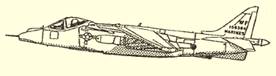 a. AV-8 Harrier: The Harrier is one of today's truly unique and most widely known military aircraft. The only fixed-wing, vertical short takeoff and landing (V/STOL) aircraft in the free world. The original design was based on a French engine concept, adopted and improved upon by the British. The U.S. Navy and Marine Corps showed a major interest in the Harrier for day or night attack and close troop ground support missions.
 b. C-130 Hercules: The C-130 Hercules is a four-engine turboprop aircraft. It’s the workhorse of the military services, capable of landing and taking off from short, rough dirt runways. It’s a people and cargo hauler that’s used in a wide variety of other roles, such as gunships, weather watchers, tankers, firefighters and aerial ambulances. There are more than 40 versions of the Hercules, and it is widely used by more than 50 nations.
 c. C-2A Greyhound: The C-2A Greyhound is a twin-engine cargo aircraft, designed to land on aircraft carriers. The C-2A Greyhound provides logistics support to aircraft carriers. It’s powered by two PT-6 turboprop engines and can deliver a payload of up to 10,000 pounds. The cabin can carry cargo, passengers, or both. It’s also equipped to accept litter patients in medical evacuation missions. Cargo such as jet engines can be transported from shore to ship in a matter of hours. A cage system or transport stand provides cargo restraint for loads during carrier launch or landing. The large aft cargo ramp and door and a powered winch allow straight-in rear cargo loading and downloading for fast turnaround. The C-2A’s open-ramp flight capability allows airdrop of supplies and personnel from a carrier-launched aircraft. This, plus its folding wings and an on-board auxiliary power unit for engine starting and ground power self-sufficiency in remote areas, provide an
 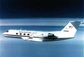 operational versatility found in no other cargo aircraft.
d. C-20 Gulfstream: The C-20D is an FAA certified Gulfstream III aircraft that provides world-wide airlift for senior leadership and dignitaries. The C-20G is an FAA certified Gulfstream IV aircraft that provides long range, medium airlift logistics support for Fleet Battle Groups.
e. C-40 Clipper: (Boeing 737) Same mission as C-9. Will eventually replace all C-9’s.
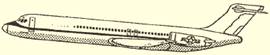 f. C-9: Sky Train The C-9 Skytrain fleet is located throughout the continental United States, Europe, and Asia. The Navy and Marine Corps C-9 aircraft provide cargo and passenger transportation as well as forward deployment logistics support. The Air Force C-9s are used for medical evacuation, passenger transportation, and special missions. The C-9 Skytrain is the military version of the McDonnell Douglas DC-9 used for many years by commercial airlines.
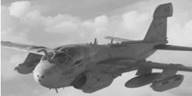 g. EA-6B Prowler:
The EA-6B Prowler was designed to compliment the Navy's defenses in today's electronic warfare environment for carrier and advanced base operations. With a crew of four, a pilot and three electronic countermeasures officers (ECMOs), this long-range, all-weather-capable aircraft has the ability to intercept, analyze, and effectively jam and neutralize hostile radar
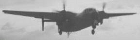
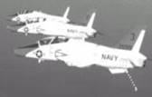
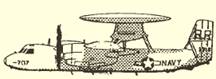 h. E-2C Hawkeye: Carrier-based airborne early warning (AEW) aircraft maintain station at some distance from a task force to provide early warning of approaching enemy aircraft and direct interceptors into attack position.
i. C-12 Huron: The C-12 Huron is a twin-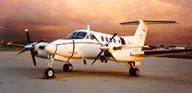 engine logistics aircraft that carries passengers and cargo between military installations. The C-12F provides logistics support between Navy air stations. It’s powered by two PT-6A-42 turboprop engines and can deliver a total payload of up to 4,215 pounds. The cabin can carry cargo, passengers, or both. It is also equipped to accept litter patients in medical evacuation missions.
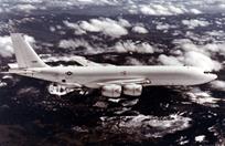 j. E-6 Mercury: Communications relay and strategic airborne command post aircraft. Provides survivable, reliable, and endurable airborne command, control, and communications between the National Command Authority (NCA) and U.S. strategic and non-strategic forces. Two squadrons, the "Ironmen" of VQ-3 and the "Shadows" of VQ-4 deploy more than 20 aircrews from Tinker Air Force Base, Oklahoma to meet these requirements.
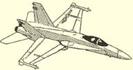 k. F/A-18 Hornet: The Hornet is a sonic, single-seat, twin-engine jet. The fighter and attack versions are identical, except for selected interchangeable external equipment. Conversion from the fighter to attack mode (and vice versa) takes less than 1 hour. The aircraft is designed for aerodynamic agility, high reliability, high survivability, and reduced manpower maintenance requirements.
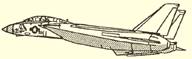 l. F-14 Tomcat: The F-14 Tomcat is an aircraft-carrier-based, jet-powered fighter aircraft. The aircraft is mainly missile oriented, carrying the new air-to-air missile, Phoenix, and capable of carrying the older Sidewinder and Sparrow. The Tomcat can be configured for bombing and rocketry.
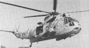 m. H-3 Sea King: The SH-3 is a twin-engine helicopter. It's used primarily for antisubmarine warfare, but it is used also for sea/air rescue and transportation. The crew consists of a pilot, copilot, sonar operator, and a relief sonar operator. Designed for land and carrier ASW operations, the A-model incorporates an automatic folding pylon. In addition to the sonar detection equipment, it is equipped with an automatic hovering device. It is capable of water landing and takeoff. Distinguishing features include a hull-shaped fuselage and outrigger sponson's, into which the main landing gear retracts. A fixed horizontal stabilizer is installed on the upper right side of the pylon, and two General Electric gas turboshaft engines are mounted side by side above the fuselage and forward of the rotor head
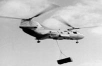 n. CH-46 Sea Knight: (USMC ONLY) The Sea Knight is a twin-turbine transport helicopter that provides the fleet with a day/night underway replenishment capability. It is used primarily for supply missions at sea and for casualty evacuation. Its carrying capacity is 25 troops, 15 litters and attendants, or 4,000 pounds of cargo. Rotor blades fold for shipboard use. The CH-46 is a small version of the Army’s Chinook.
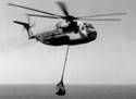 o. CH-53 Sea Stallion: The Sea Stallion tows and operates various mine countermeasure devices designed to detect and neutralize submerged naval mines. CH-53D squadrons are capable of rapid worldwide deployment.
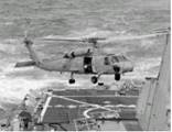 p. SH-60B/SH-60F/HH-60H/MH-60S Sea Hawk: The Seahawk SH-60B is placed aboard frigates and destroyers. The Seahawk is the airborne platform segment of the LAMPS Mk III weapons system. It can carry personnel as well as weapons to detect, localize, and destroy submarines at long range. It is designed to be in constant voice and data link contact with the ship’s CIC. In addition to its primary mission of seeking and engaging submarines many miles from the ship, the Seahawk helicopter is able to provide targeting information for over-the-horizon, surface-to-surface missiles. The secondary mission of the Seahawk helicopter is search and rescue, medical evacuation, vertical replenishment, and communications relay.
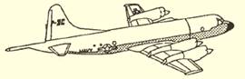 q. P-3 Orion/EP-3 Aries: The P-3 Orion is equipped with magnetic anomaly detection (MAD) gear, sonobuoys, radar, and other submarine detection systems. It is armed with torpedoes, bombs, missiles, and depth charges for kills. It has the primary mission of detecting, locating, and destroying enemy submarines. The P-3 Orion can respond quickly to hunt down submarine contacts long before surface units can arrive. Other duties include convoy escort, photographic missions, and aerial mining
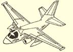 r. S-3B Viking: The S-3 Viking is an example of such an aircraft. The Viking is a high-wing, jet-powered, twin-engine, carrier-based ASW aircraft. It carries surface and subsurface search equipment with integrated target-acquisition and sensor-coordinating systems that collect, interpret, and store ASW sensor data. It has direct attack capability with a variety of armaments.
s. T-44 Pegasus : Training
 t. T-45 Goshawk: The T-45A Goshawk is a tandem-seat, carrier capable, jet trainer. The T-45A aircraft is used for intermediate and advanced portions of the Navy/Marine Corps pilot training program for jet carrier aviation and tactical strike missions. There are two versions of T-45 aircraft currently in operational use at this time.
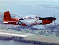 u. T-34 Turbomentor: The T-34C Turbomentor is an unpressurized two-seat, tandem cockpit low-wing turboprop trainer. The T-34C is used to provide primary flight training for student pilots attached to the Chief of Naval Air Training. As a secondary mission, approximately 10 percent of the aircraft provide pilot proficiency and other aircraft support services.
v. T-39 Sabreliner
 w. V-22 Osprey
x. AH-1W Super Cobra
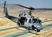
y. UH-1N: Huey Utility helicopter, primarily used for search and rescue, command and control and maritime special operations missions.
z. T-6 Texan
.28 Discuss the operating principles and uses of radar. [ref. b, ch. 7]
* Radio Detection and Ranging (RADAR)
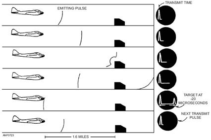 A radio device used to detect objects at distances much greater than is visually possible. Detectable objects include aircraft, ships, land, clouds, and storms. Radar also shows their range and relative position. Radar works on an echo principle. Sound waves travel out and by knowing the speeds and the time it takes for them to return as an echo, the distance can be measures. One radar range mile is 12.36 microseconds. That is the time it takes for a radio wave to travel out and return back for one mile.
.29 Explain the use and modes of IFF. [ref. b, ch. 7]
* Identification Friend or Foe (IFF)
IFF is an electronic system that allows a friendly craft to identify itself automatically before approaching near enough to threaten the security of other naval units. A transponder in the friendly aircraft receives a radio-wave challenge. The transponder transmits a response to a proper challenge. All operational aircraft and ships of the armed forces carry transponders to give their identity when challenged.
.30 Describe the information provided by the inertial navigation system.
[ref. b, ch. 7]
* An inertial navigation system (INS) is an automatic aid to navigation that is independent of outside references. An INS is a portion of the overall tactical system that provides accurate velocity, attitude, and heading data to a digital data processing system. This overall system permits accurate weapons delivery. To function properly, the system must be aligned with reference to initial conditions of altitude, latitude, and longitude.
* This system can make the following computations during flight:
1. The latitude and longitude of the present position of the aircraft. This information is continually displayed on the pilot's console.
2. The aircraft ground track angle, relative to true heading.
3. The distance from the present position of the aircraft to a preset target or base, as selected on the control panel
4. The bearing of the preset target or base, as selected, relative to true heading.
.31 State the aviation mission of each of the following ships: [ref. k]
a. AE - Ammunition Ship
They operate with replenishment groups to deliver ammunition and missiles to ships at sea. These ships handle all types of missiles. They carry two H-46 helicopters for vertical replenishment and support.
b. AFS -
c. AO/AOE - Oiler/Oiler and Ammunition Support Ships
AO: These ships carry fuel, jet fuel, and other petroleum products. They operate with replenishment groups and deliver their cargo to ships at sea. They can service from both sides of the ship simultaneously.
AOE: The largest and most powerful auxiliary ship in the Navy. AOE ships carry missiles, fuel, ammunition and general cargo. They can also carry refrigerated cargo and supplies. They carry two H-46 helicopters for vertical replenishment and support.
d. CG - Guided Missile Cruiser
These ships serve provide protection against surface and air attacks and gunfire support for land operations. They have a large cruising range and are capable of speeds over 30 knots. Some cruisers are capable of conducting anti air warfare, antisubmarine warfare, and anti-surface ship warfare at the same time. They carry one or two LAMPS Mk III SH-60B helicopters.
e. CV/CVN - Carrier/Nuclear Powered Carrier
Carriers are designed to carry, launch, retrieve and handle combat aircraft quickly and efficiently. It can approach the enemy at high speed, launch planes, recover them, and retire before its position can be determined. Attack carriers are excellent long-range offensive weapons and are the center of the modern naval task force or task group.
f. DD/DDG - Destroyer/Guided Missile Destroyer
Multipurpose ships used in any kind of naval operation. Fast ships with a large variety of armament and little or no armor. They depend on their speed and mobility for protection. They operate offensively and defensively against subs and surface ships. They can take defensive action against air assaults. They provide gunfire support for amphibious assaults. They can perform patrol, search and rescue missions, if needed. They can accommodate two SH-60B or 2 SH2G helicopters.
g. FFG - Guided Missile Frigates
Frigates are used for open-ocean escort and patrol. They resemble destroyers in appearance, but are slower, have only a single screw, and carry less armament. They can carry two SH-60B helicopters.
h. LCC - Amphibious Command Ship
Provides accommodations and command and communication facilities for various commanders and their staffs. They can serve as a command ship for an amphibious task force, landing force, and air support commanders during amphibious operations. They are the most modern and capable command facilities afloat.
i. LHA - Amphibious Assault Ship,
These ships are able to embark, deploy, and land a Marine battalion landing team by helicopters, landing craft, amphibious vehicles, and combinations of these methods. They are versatile and combine the same features of the Amphibious Assault ship (LPH), Amphibious Transport Dock (LPD), Amphibious Cargo Ship (LKA), and Dock Landing Ship (LSD) in a single ship.
LHD - Amphibious Warfare Ship
They are designed based on that of an Amphibious Assault Ship, but are intended to be convertible from an Assault Ship to an Anti-submarine Warfare ship with Harrier fighters for ground assault.
j. LPD - Amphibious Transport Dock
Combines the features of a Dock Landing Ship (LSD), with the features of an Amphibious Assault Ship (LPH). They can transport troops and equipment in the same ship. It has facilities for 8 helicopters.
k.MCS - Mine Countermeasures Support Ship
There is only one of these in the naval inventory - the USS Inchon.
 .32 Identify and explain the purpose of the following aviation ratings: [ref. b, ch. 1]
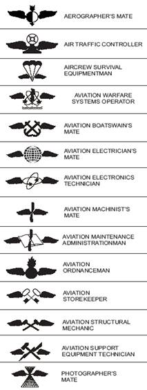
a. AB: Aviation Boatswain Mate
b. AC: Air Traffic Controller
c. AD: Aviation Machinist's Mate
d. AE: Aviation Electrician's Mate
e. AG: Aerographer's Mate
f. AM: Aviation Structural Mechanic
g. AO: Aviation Ordnanceman
h. AS: Aviation Support Equipment Technician
i. AT: Aviation Electronics Technician
j. AW: Airwarfare Systems Operators
k. AZ: Aviation Maintenance Administrator
l. PH: Photographer’s mate
m. PR: Aviation survival equipmentman
.33 Explain the use of basic electrical schematics and block diagrams. [ref. e, ch. 3]
* SCHEMATIC DIAGRAM: The schematic diagram shows, by means of graphic symbols, the electrical connections and functions of a specific circuit arrangement. The schematic diagram is used to trace the circuit and its functions without regard to the actual physical size, shape, or location of the component devices or parts.
The schematic diagram is the most useful of all the diagrams in learning overall system operation.
Figure 3-10 is a schematic diagram of an automobile electrical system. The automobile electrical system uses the frame of the automobile as a conductor. The frame is called the ground side. Figure 3-10 shows all the electrical components grounded on one side. The negative side of the battery is also grounded. Therefore, the frame is the negative conductor of the system. The opposite side of each of the components is connected through switches to the positive side of the battery. For the purpose of teaching schematic reading, we will discuss only the lighting system and engine instruments.
* BLOCK DIAGRAM : A block diagram is used primarily to present a general description of a system and its functions. This type of diagram is generally used in conjunction with text material. A block diagram shows the major components of a system and the interconnections of these components. All components are shown in block form, and each block is labeled for identification purposes. The block diagram shown in figure 3-8 is an illustration of an automobile's electrical power, starting, and ignition systems. It must be emphasized that the following explanation is primarily for the purpose of assisting you in learning to "read" or interpret a block diagram. The explanation of the functions of the automobile power, starting, and ignition systems is of secondary importance. By tracing from component to component in the block diagram and following the explanation, you are given a general description of the system functions. In addition, you should be able to understand the arrangement of the components in a block diagram.
.34 State the purpose of wiring and cable identification codes. [ref. e, ch. 3]
* THE PURPOSE OF IDENTIFICATION CODES: Cables and wires are marked to give the technician a means of tracing them when troubleshooting and repairing electrical and electronic systems. Numerous cable- and wire-marking systems are used in ships, aircraft, and equipment throughout the Navy. A few of these systems are briefly discussed here to acquaint you with how marking systems are used. For a specific system or equipment, you should refer to tile applicable technical manual.
* CABLE-MARKING SYSTEMS: Two typical cable-marking systems you are likely to see are the (1) shipboard and (2) test equipment cable-marking system
* WIRE-MARKING SYSTEMS: Wire-marking systems are used to identify wires in aircraft, shipboard electronic equipment, and power tool and appliance cables.
* Example of Aircraft Wire-Marking Systems
All aircraft wiring is identified on wiring diagrams exactly as the wire is marked in the aircraft. Each wire is coded by a combination of letters and numbers (figure 3-3) imprinted on the wire at prescribed intervals along the wire run.

.35 Explain the purpose of the following:
a. Circuit breaker [ref. g, ch. 2]: A protective device that opens a circuit when the current exceeds a predetermined value. Circuit breakers can be reset.
b. Fuse [ref. g, ch. 2]: A protective device inserted in-line with a circuit. It contains a metal that will melt or break when current is increased beyond a specified value, thus disconnecting the circuit from its power source to prevent damage.
c. Multimeter [ref. h, ch. 4]: During troubleshooting, you will often be required to measure voltage, current, and resistance. Rather than using three or more separate meters for these measurements, you can use the MULTIMETER. The multimeter contains circuitry that allows it to be used as a voltmeter, an ammeter, or an ohmmeter. A multimeter is often called a VOLT-OHM-MILLIAMMETER (VOM). One of the greatest advantages of a VOM is that no external power source is required for its operation; therefore, no warm-up is necessary. Other advantages are its portability, versatility, and freedom from calibration errors caused by aging tubes, line voltage variations, and so forth.
d. TDR [ref. h, ch. 4]: A time-domain reflectometer (TDR) is an electronic instrument used to characterize and locate faults in metallic cables (for example, twisted wire pairs, coaxial cables) and, in the OTDR domain: optical fibers.
Time Domain Reflectometers are commonly used for in-place testing of very long cable runs, where it is impractical to dig up or remove what may be a kilometers-long cable. They are indispensable for preventive maintenance of telecommunication lines, as they can reveal growing resistance levels on joints and connectors as they corrode, and increasing insulation leakage as it degrades and absorbs moisture long before either leads to catastrophic failures. Using a TDR, it is possible to pinpoint a fault to within feet or inches.
TDRs are also very useful tools for surveillance countermeasures, where they help determine the existence and location of wire taps. The slight change in line impedance caused by the introduction of a tap or splice will show up on the screen of a TDR when connected to a phone line.
TDR equipment is also an essential tool in the failure analysis of today's high-speed printed circuit boards. The signal traces on these boards are carefully crafted to emulate a transmission line. By observing reflections, any unsoldered pins of a ball grid array device can be detected. Additionally, short circuited pins can also be detected in a similar fashion.
The TDR principle is used in industrial settings, in situations as diverse as the testing of integrated circuit packages to measuring liquid levels. In the former, the time domain reflectometer is used to isolate failing sites in the same. The latter is primarily limited to the process industry.
e. Megohmmeter [ref. i, ch. 8]: MEGOHMMETER (MEGGER), The megohmmeter, commonly called the megger, is an instrument that applies a high voltage to the component under test and measures the current leakage of the insulation. This lets you check a capacitor or an insulated cable for leakage under much higher voltages than an ohmmeter can supply. The megger consists of a hand-driven dc generator and an indicating meter. It measures resistances of many megohms.
Meggers are used for testing capacitors whose peak voltages are not below the output of the megger. They are also used for testing for high-resistance grounds or leakage on devices such as antennas and insulators.
.36 Explain the following avionics terms: [ref. j]
a. Voltage: The "driving force" behind current. Voltage, as applied to Ohm's Law, can be stated to be the base value in determining unknown circuit values. Designated by the letter (E).
b. Current: The flow of electrons. Ohm's Law states that current is directly proportional to the applied voltage and inversely proportional to the circuit resistance. Designated by the letter (I).
c. Resistance: The opposing force to the flow of electrons. As stated in Ohm's Law, current is inversely proportional to resistance. This means, as the resistance in a circuit increases, the current decreases proportionally. Designated by the letter (R).
Note: Ohm's Law states E=IR
.37 Explain HERO. [ref. f, ch. 11]
* HAZARDS OF ELECTROMAGNETIC RADIATION TO ORDNANCE (HERO)
The functional characteristics of electrically initiated ordnance cause hazards of electromagnetic radiation to ordnance (HERO). Ordnance that presents a HERO problem includes cartridges, cartridge-actuated devices, and 20-mm ammunition. The ordnance electro-explosive devices (EEDs) may be accidentally initiated or their performance degraded by exposure to radio frequency (RF) environments. Ordnance is more susceptible to RF environments during assembly, disassembly, handling, loading, and unloading operations.
The term RADHAZ (radiation hazards) applies to radio frequency (RF) electromagnetic fields of sufficient intensity to
* produce harmful biological effects in humans, and/or
* cause spark ignition of volatile combustibles or actuate electroexplosive devices. Although the effects of RADHAZ are important, this chapter limits discussion to HERO hazards.
* HERO ORDNANCE CLASSIFICATIONS
A testing program sponsored by the Naval Sea Systems Command (NAVSEASYSCOM) determines the susceptibility of ordnance to RF environments. Tests are conducted in the maximum RF environment the ammunition or ordnance systems may be subjected to in its stockpile-to-launch sequence. This data is the basis for the three HERO classifications assigned to ordnance—HERO-safe ordnance, HERO-susceptible ordnance, and HERO-unsafe ordnance.
.38 Discuss the improper use of white lights during night operations. [ref. l, ch. 2]
* Self explanatory
.39 Discuss the dangers of working near aircraft intakes/exhaust and propeller/rotor arc. [ref. m, WP 004]
* Self explanatory
.40 Discuss the effects of hot exhaust gases on ordnance, external stores, aircraft, and equipment. [ref. n, ch. 6; ref. o, ch. 7]
* Hot exhaust from aircraft starting units is a serious hazard when operating in close proximity to other aircraft, aircraft components, fuels, weapons, equipment, and personnel.
.41 Explain the dangers of standing behind JBD with aircraft at high power settings. [ref. o, ch. 4]
* The controlling plane director shall ensure that aircraft with wings folded or canopy open are not spotted, towed or taxied immediately behind a jet blast deflector when another aircraft is at high power setting on the catapult.
.42 Discuss the potential personnel and equipment hazards when engaging and disengaging rotors. [ref. p, ch. C7]
* Self explanatory
.43 Discuss the hazards of stepping across the catapult track during launch and retract. [ref. o, ch. 4]
* Self explanatory
.44 Discuss how aircraft are tied down to prevent movement. [ref. o, ch. 2]
* Tie down requirements are divided into four categories as defined by the following:
a. Initial Tie down. This condition of aircraft security exists immediately prior to aircraft movement from spot and immediately after aircraft is parked. With the ACHO’s approval, aircraft scheduled for “launch” on any given cyclic or CARQUALS events, with the exception of “spare” aircraft, shall be on initial tie downs. Initial tie downs installation after recovery or re-spot is the responsibility of the plane handling crew. As a minimum, initial tie downs are required for all refueling operations.
b. Intermediate Tie down. This condition of aircraft security shall exist during flight quarters. Aircraft that are not scheduled for launch on any given cyclic or CARQUALS events shall be on intermediate
tie downs. Intermediate tie down installation is the responsibility of the plane captain.
c. Permanent Tie down. This condition of aircraft security is required when not at flight quarters or when the aircraft is not expected to fly or be re-spotted. Aircraft parked on the hangar bay shall be on permanent tie downs.
d. Heavy Weather Tie down. This condition of aircraft security is required upon the determination of the Aircraft Handling Officer.
The following tie down conditions are provided as a minimum guide for safe handling operations of shipboard aircraft and may be increased as conditions necessitate.
Security Conditions
Aircraft Type Initial Intermediate Permanent Heavy Weather
E-2*, C-2*, F-14*, EA-6, F/A-18, S-3 6 9 12/14* 18/20*
AV-8, T-45, H-3, H-46, H-53, H-60 4 6 12 16
.45 Discuss the effects of turbojet/turbofan/turboprop aircraft engines ingesting hot exhaust. [ref. o, ch. 7]
* Self explanatory
.46 Discuss the dangers of the landing area during recovery. [ref. o, ch. 5]
* In addition to the basic safety precautions used during operational procedures, the following special safety precautions shall be observed:
1. All topside personnel shall be in the proper flight deck uniform.
2. Personnel shall not stand in or otherwise block entrances to the island structure, or exits leading from the catwalks.
3. Avoid crowding of personnel or material in the catwalk areas near the deck edge control station.
4. During recovery operations, with the exception of the LSO and his assistants, no personnel shall be permitted in the port catwalk without authorization from the Air Officer.
5. Personnel shall not turn their backs on aircraft landing or taxiing out of gear; they shall stay alert and in a position that allows quick and agile movement.
6. Personnel required to be in the catwalks shall duck below the flight deck or behind cable shields during the aircraft’s touch down and rollout.
7. Personnel in the rollout area shall position themselves behind tractors or other mobile equipment as feasible.
8. Hook Runners, Gear Puller, and other personnel in the rollout area shall not enter the landing area until the aircraft has completely stopped.
9. No one shall enter the landing area to effect equipment repairs, or for any other reason, until the deck is “fouled” and until positive clearance has been obtained from the Arresting Gear Officer. If crossing the landing area is absolutely necessary during flight operations, the following procedures shall be followed:
a. Personnel shall stay clear of the foul line; and shall check the aircraft in the pattern.
b. If the pattern is clear, the individual shall get the Arresting Gear Officer’s attention and indicate desire to cross by pointing across the deck.
c. The Arresting Gear Officer shall check the pattern. If the pattern is not clear, no response will be seen from him. The Arresting Gear Officer is busy and will continue with his duties.
d. If pattern is clear, the arresting gear officer will point at the individual and then swing arm in a horizontal motion to point to the other side of the landing area. A red wand will be used to point with at night.
e. After receiving clearance, the individual shall run straight across the deck, staying at least 10 feet aft of the No. 1 wire. This will prevent tripping over the wire supports or being struck by the No. 1 wire during the wire retraction.
Warning: If the arresting gear crew is required to enter the landing area during aircraft recovery, a safety man shall be stationed forward of the crew, facing aft with arms crossed over head; at night the safety man shall have a red wand held vertical, to ensure crew safety and observe approaching aircraft.
10. The Deck Edge Operator shall stand well clear of the retract lever while personnel are on deck and all purchase cables are not fully retracted.
11. Purchase cables shall never be fed back through the flight deck sheave by hand. The arresting engine shall retract purchase cables.
To minimize the possibility of an aircraft landing on a fouled deck, the following procedures are mandatory:
1. The lens, and at night the landing area lights, shall never be turned on without the expressed permission of the Air Officer.
2. Except for the purpose of conducting tests, neither the lens nor the landing area lights will be turned on until the LSO has manned the platform.
3. The wave-off lights shall be continuously activated any time the lens or landing area lights is turned on and the LSO is not on the platform.
4. Practice CCA approaches, using visual landing aids, shall be permitted only when the LSO is on the platform. He shall wave off each aircraft at ½ mile or greater.
5. To avoid unnecessary delay in recovering the first aircraft, the lens and/or landing area lights may be turned on a short time before the ship is completely ready to commence recoveries, but wave-off lights shall be continuously activated until an LSO is on station. The LSO shall wave off approaching aircraft at a distance of ½ mile or greater if he has not received the “clear deck” signal.
6. During instrument recoveries, PriFly will keep CATCC advised as to the status of the deck and provide the estimated time the deck will be clear. CATCC will keep PriFly advised as to the position of the nearest aircraft.
7. Combat and CATCC shall keep PriFly informed of any aircraft known or suspected to have radio failure.
8. PriFly will notify the Arresting Gear Officer and Flight Deck Officer of any aircraft with problems that will affect recovery (lights, electrical problems, fuel, hydraulic, control, flaps, etc.).
.47 Discuss the dangers of walking through the arc of a static propeller/rotor arc.[ref. m, WP 004]
* Self explanatory
.48 Discuss personnel movement on the flight deck during flight operations.
* Self explanatory
.49 Explain the protective functions of the following: [ref. q]
a. Engine duct covers
b. Engine intake inspection
c. Engine turn up screens
d. Other aircraft protective covers
e. Authorized FOD containers
f. Drip pans
* Self explanatory
.50 Locate on a diagram the following areas of a flight deck: [ref. q]
a. Aircraft elevators b. Flight deck control
c. Weapons elevators d. Patio/shelf
e. Junkyard f. Helo landing spots
g. Arresting cables h. Barricade
i. Catapults j. LSO platform
k. Finger l. Crotch
m. Corral n. Point
o. Six-pack p. Street
.51 Locate on a diagram the following areas of an aircraft carrier hangar deck: [ref. q]
a. Hangar deck control b. Conflagration stations
c. Bay one d. Bay two
e. Bay three f. Divisional doors
g. Elevator doors h. Aircraft elevators
i. Weapons elevators j. Sprinkler group activation
k. AFFF stations l. CO2 bottles
m. PKP bottles n. Fire lane
o. Fuel stations p. OBA/SCBA locker
q. Medical/first aid box r. BDS
s. O2/N2 plant t. Engine container storage area
u. Repair lockers
* AFFF Station Markings
An 18-inch-wide green strip is painted up and over the deck-edge wheel-stop coaming. A white, 3-inch-high “AFFF” is painted in the center of the stripe. At locations where coaming is not installed, the stowage location is marked by a green, 18-inch square painted on the flight deck with white “AFFF” letters painted in the center of the square.
AFFF is the primary extinguishing agent for aircraft fires on all Navy air-capable ships. Operating a typical flight-deck AFFF station is simple.
l. First – Locate the activation button and the telephone (they are painted green).
2. Second – Make sure the firefighting crew has pulled out all the fire hose from the storage box.
.52 Identify the personnel wearing the following color jersey and discuss their duties:
[ref. o, ch. 2]
a. Green
1. Catapult Safety Observer–Is a direct representative of the launching officer makes sure people follow launch procedures and precautions.
2. Topside Safety Petty Officer (TSPO) – Ensures that holdbacks and repeatable-release assemblies are installed, and that the aircraft’s launch bar is seated in the shuttle spreader. For bridle aircraft, the TSPO makes sure the bridle is engaged with the spreader and the aircraft’s tow fittings. They are the last people to exit from
under the aircraft.
3. Holdback Personnel (Non-Bridle) –Install holdbacks and repeatable-release assemblies. For bridle aircraft, they install tension rings and bars and holdback assemblies. They also verify
position.
4. Hook-up Crew (Bridle) –Engage the bridle to aircraft hookup points.
5. Center deck Operator–Communicates with catapult control, relaying aircraft type, gross weight, side number, and capacity selection valve settings for the launching officer.
6. Jet-Blast Deflector (JBD) Operator–Raises and lowers the jet blast deflectors for each aircraft. The JBD prevents jet blast from hitting personnel and aircraft aft of the catapult launching area.
7. Weight-Board Operator–Verifies the aircraft gross weight with the aircrew as a final check before launch. Each plane requires a different catapult CSV setting based on aircraft weight.
8.Topside Petty Officer (TPO) –Supervises the arresting-gear topside crew. Responsible to the AGO for ensuring topside arresting-gear equipment is in good working order.
9. Deck-Edge Operator–Retracts the arresting gear after recovery of each aircraft. Is stationed in the catwalk.
10. Hook Runners–Ensure cross-deck pendant and purchase cable have been disengaged from the aircraft tail hook, and, when the landing
area is clear, they give retract signal to the deck edge operator.
11. Aircraft Maintenance Crew– Maintain the aircraft. Their jerseys are marked with a squadron designator and black stripe on the front and back.
12. Helicopter LSE (Landing Signalman Enlisted) – Directs the takeoff and landing of all helicopters with visual hand signals. The LSE wears a red helmet.
13. Photographers – Capture images and videotape flight operations for documentation and media requests.
14. Deck Checkers – Ensure the landing area is FOD free, the wire is in position for aircraft recovery, and all personnel are clear of landing area.
b. Yellow
1. Aircraft handling officer
2. Catapult and arresting gear officer
c. Red
1. Crash and salvage crews
2. Explosive ordnance disposal
3. Ordnance
4. CAG Arm/ De-arm
d. Brown
* Plane Captains - Make sure aircraft are inspected and serviced before and after each flight. They are responsible for the cleanliness and general condition of the aircraft. They also supervise ground-starting procedures. Their jerseys are marked with their squadron designator on the front and back.
e. Blue
1. Tractor driver
2. Aircraft handling crew and chock men
f. Purple
1. Aviation fuel crew
g. White
1. Transfer officer
2. Safety
3. QA
4. LOX crew
5. Landing signal officer
6. Trouble shooter
.53 Recognize and describe the following visual hand signals needed for day and night flight operations: [ref. r, ch. 2]
a. Affirmative (all clear) b. Negative (not clear)
c. Turn to left d. Turn to right
e. Move ahead f. Stop
g. Personnel approaching aircraft h. Insert chocks
i. Remove chocks j. Connect ground electrical power
k. Disconnect ground electrical power l. Start engine(s)
m. Cut engine(s) n. Fold wings/helicopter blades
o. Spread wings/helicopter blades p. Fire
q. Remove chocks and/or tie down r. Insert chocks and/or install tie do
s. Hot brakes t. Raise hook
u. Lower hook v. Move upward
w. Hover x. Move downward
y. Move to left z. Move to right
aa. Droop stops out ab. Droop stops in
ac. Engage rotor(s) ad. Set rotor brake
ae. Install tie downs (LSE) af. Hold position
* Self Explanatory
.54 Explain the four classifications of fire and the appropriate extinguishing agent.[ref. s, ch. 2]
1. Class A Fires: burning wood and wood products, cloth, textiles and fibrous materials, paper and paper products) are extinguished with water in straight or fog pattern. If fire is deep seated, AFFF can be used as wetting agent.
2. Class B Fires: (gasoline, jet fuels, oil, and other flammable/ combustible liquids) are extinguished with AFFF, Halon 1211, PKP, and CO2.
3. Class C Fires: involves energized electrical equipment. Extinguishment tactics are: de-energize and treat as a Class A, B, or D fire; attack with application of non-conductive agents (CO2, Halon, PKP); or attack with application of fresh or salt water in fog patterns maintaining nozzle at least 4 feet from the energized object.
4 Class D Fires: (combustible metals such as magnesium and titanium) are extinguished with water in large quantities such as high velocity fog. When water is applied to burning Class D material, there may be small explosions. The firefighter should apply water from a safe distance or from behind shelter.
.55 Identify and explain the use of the following:
a. AFFF stations [ref. s, ch. 3]
b. Portable fire bottles [ref. s, ch. 3]
c. Countermeasure wash down system [ref. t, ch. 5]
d. Mobile firefighting unit (P-25/A) [ref. u, ch. 3]
e. Shipboard TAU [ref. s, ch. 4]
* See section 51
.56 Discuss the responsibilities of the crash and salvage crew: [ref. s, ch. 7]
* The crash, salvage, and rescue team is the flight deck repair team. From its station in the island structure it serves to effect rescue of personnel from damaged aircraft on the flight deck, clear away wreckage, fight fires on, and make minor emergency repairs to the flight deck and associated equipment.
.57 Identify the equipment designation(s) and explain the use of the following support equipment and their associated hazards: [ref. m]
a. Tow tractor [WP 005]
b. Tow bar [WP 005]
c. Aircraft starting unit (mobile/installed) [WP 012]
d. Mobile electric power plant [WP 010]
e. Nitrogen servicing [WP 007]
f. Oxygen servicing (gaseous/liquid) [WP 007]
g. Carrier crash crane [WP 006]
h. Hydraulic servicing unit [WP 008]
i. Hydraulic power supply [WP 008]
j. Hangar deck crane [WP 006]
k. Oil servicing unit [WP 008]
l. Mobile air-conditioner [WP 011]
m. Corrosion control cart [WP 015]
* Self explanatory
.58 Discuss the responsibilities of the following personnel: [ref. o, ch. 1]
a. Air Officer (air boss): The Air Officer is directly responsible for all operational, training, administrative, watch, and equipment repair functions within the Air Department. He is further responsible for determining the case launch and/or recovery, the visual control of all aircraft operating in the carrier control zone, carrier control zone clearing authority and all other duties specified in NAVAIR 00-80T-105 (CV NATOPS) related to air operations.
b. Assistant Air Officer (mini boss): The Assistant Air Officer aids the Air Officer in ensuring that the plans, orders, and instructions of the Air Officer are carried out. He acts as Assistant Department Head. He also functions as the Air Department Training Coordinator
c. ACHO: The Aircraft Handling Officer, under the Air Officer ensures the ship is capable of meeting all mission requirements related to flight and hangar deck air operations, and in many instances, other departmental requirements as well. He regulates the number of aircraft on the flight and hangar deck to execute all evolutions including cyclic operations, carrier qualifications, vertical and conventional replenishment, and alert postures. He serves as the Team Leader of the Air Department Training Team and assists the Air Wing Watch Coordinator in training personnel for the Aircraft Integrity Watch.
d. Crash and Salvage Officer/air boatswain: The Aircraft Crash and Salvage Officer is responsible for supervising crash crews and fire parties in handling aircraft emergencies during flight and general quarters, and for ensuring the readiness of assigned personnel, firefighting, and salvage equipment. He is also responsible for the overall training of Air Department and Air Wing personnel in aircraft firefighting and crash and salvage operations.
e. Flight Deck Officer (V-1 Division): The Flight Deck Officer is responsible for the safe and efficient movement of aircraft on the flight deck, aircraft security and flight deck cleanliness. The Flight Deck Officer is responsible for the training and administration of V-1
Division as well as the overall material condition of all divisional spaces both internal and external. He assists the ACHO in the execution of the flight plan.
f. Catapult and Arresting Gear Officer (V-2 Division): The Catapult and Arresting Gear Officer is responsible for the safe and efficient operation of the ship’s Aircraft Launch and Recovery Equipment (ALRE). The Catapult and Arresting Gear Officer is responsible to the Air Officer for the operation, maintenance, and readiness of the launching and recovery systems. He is overall responsible for the operation and upkeep of the catapults, arresting gear, and visual landing aids.
The Catapult and Arresting Gear Officer is responsible for the overall training of V-2 Division and the training of prospective Catapult and Arresting Gear Officers. He shall ensure that a complete, comprehensive, and vigorous training program is implemented.
g. Hangar Deck Officer (V-3 Division): The Hangar Deck Officer is responsible for the safe, efficient movement of aircraft and overall maintenance of the hangar deck, training of personnel, readiness of damage control and aircraft handling support equipment.
h. Aviation Fuels Officer (V-4 Division): The Aviation Fuels Officer is responsible for the training of all aviation fuels personnel, safe and efficient operation of the aviation fuel system, and the management of the aviation fuel quality control program. He also is responsible for ensuring strict compliance with all applicable directives concerning the inspection, maintenance, and operation of aviation fuel systems.
.59 Discuss the function of reconnaissance photography. [ref. v]
* The Navy performs aerial reconnaissance photography of enemy territory to observe enemy defenses, troop concentrations, troop movements, enemy strength, and so on. Aerial reconnaissance photography may also include taking images over friendly territory, both ours and our Allies. Refer to TARPS.
.60 Discuss the altitude range for the following types of aerial photography: [ref. v]
a. Low altitude: 0 to 1,500 feet
b. Medium altitude: 1,500 to 10,000 feet
c. High altitude: 10,000 feet and above
* As a Photographer’s Mate, your aerial photographic assignments are normally accomplished from low to medium altitudes.
.61 Define the following terms and explain their use: [ref. w]
a. SLAR photography: SIDE-LOOKING AIRBORNE RADAR (SLAR OR SLR)— An airborne radar that produces an image of a portion of the surface of the Earth by means of one or more antennas viewing at approximately right angles to the longitudinal axis of the aircraft
Radarscope photography is a film record of the activity on the radar screen (scope). Radar normally is a phenomenon involving aimed radiation through space and its consequent reflection. Therefore, effective radarscope reconnaissance is possible with radar equipment operating from aircraft, from ships, from submarines, and on the ground as long as the objective area is not masked by a mass that cannot be penetrated by the radar signal. The radarscope image makes possible effective all-weather operations. Radarscope photographic reconnaissance provides the following information:
1. Information on prestrike, strike, and post-strike intelligence;
2. Information to assist all-weather offensive operations; and
3. Information used in constructing new maps or correcting existing ones.
b. FLIR photography: Forward-Looking Infrared (FLIR). In a combat situation, the imagery obtained from line scan recording systems is often too late for tactical reaction. In response to this situation, specifications were set up to provide a real-time readout capability for aircrews. Many real-time readout line scan systems were tried. However, the imagery presented on the cathode-ray tube (CRT) was still only that which the aircraft had just flown over, and no immediate reaction was possible. This brought about the integration of a forward-looking infrared, or FLIR, system with an active weapons system, thus providing immediate reaction to the information obtained.
The FLIR is a passive detection system used primarily for recognition and identification of surface ships, submarines, and submarine wakes. Secondary functions include target verification, weapon delivery observation, and navigation landmark identification.
c. IR system: Infrared (IR) Reconnaissance Systems. Many details of operational IR sensors are classified. This section provides unclassified information pertinent to current infrared-sensing techniques. The most significant difference between a conventional camera system and an IR system is the source of the electromagnetic radiation they record. Visible light waves imaged by cameras are the result of reflections from the target of a light source independent of the target, such as the sun or a flash cartridge. On the other hand, IR waves result either from energy within the target itself or from energy that the target absorbs and subsequently releases or emits. Thus, IR radiation can be recorded at night when the target releases, as heat, the energy absorbed from the sun during the day. Daytime IR images, however, can be both reflected and emitted radiant energy.
.62 Discuss the operational interface between the TARPS and the F-14 aircraft. [refs. v, x]
* TARPS: Tactical Air Reconnaissance Pod System.
* With the development of the F-14 Tomcat equipped with the TARPS, the Navy continues to improve its photographic reconnaissance capabilities. The TARPS pod, containing two optical cameras and an infrared detection system, is attached to a specially configured F-14 called the Peeping Tom.
* Although retaining all the air superiority characteristics of the non-TARPS F-14, the Peeping Tom gives tactical commanders a wide range of sensor capabilities, including day/night, high/low altitude coverage as well as high-speed penetration and medium-range standoff reconnaissance.
* The camera systems are comparatively simple to operate, and the pod itself is equally easy to service and maintain. Current CV assets can provide complete support for the system, from film processing to final intelligence analysis and dissemination. Finally, because the Peeping Tom is still fully fighter capable, those aircrews that are identified with the program have the distinction of being both fighter and reconnaissance qualified, thus assuring themselves an even greater role in the fleet.
* The pod is designed to be aerodynamically and structurally suitable for supersonic flight. It is non-jettisonable and is attached directly to the starboard-underside of the fuselage at weapons station number 5. Operation of the reconnaissance system in the pod is controlled by the Naval Flight Officer/Radar Intercept Officer (NFO/RIO) (back-seater) using the Computer Processor Signal/Sensor (CPS). In addition, the pilot is provided with a camera on/off capability via the bomb button on the control stick.
* Target location and camera control information is given to the crew by the Tactical Information Display (TID) and the Heads Up Display (HUD). The TARPS-equipped Tomcats retain a significant offensive capability, even when they are carrying out a photographic role. The aircraft can be returned to full combat configuration in a few minutes by removing the external TARPS.
* Each squadron having TARPS aircraft is assigned enlisted Intelligence Specialists who work in a ground support role at the squadron level along with the Intelligence Specialists operating in the Aircraft Carrier Intelligence Center (CVIC). TARPS contains the following reconnaissance sensor and auxiliary equipment:
1. Pod;
2. Environmental Control System (ECS);
3. KS-87B Camera;
4. KA-99A Camera;
NOTE: When the KA-99A low-altitude panoramic camera is mounted in bay 2 of the TARPS pod, about 4 inches port and 3 inches starboard in the field of view (FOV) are lost due to the imaging of the external fuel pods mounted under the wing of the F-14 Tomcat. This results in a loss of about 7 inches in film format from a total of 28.3 inches of the format size.
5 KS-153 Camera;
NOTE: This camera is fitted in station 2 in place of the KA-99 when mission requirements dictate. The KS-153 camera is a 24-inch sensor that uses three vertical/oblique 9 x 9-inch shots to simulate pan.
6. AN/AAD-5 Infrared Line Scan (IRLS);
7. Maintenance Control Panel;
8. Sensor Control/Data Display Set (SC/DDS); and
9. Reconnaissance Control Processor Unit (RCPU).
* Miscellaneous hardware includes the following equipment:
1. KS-87B camera-mount;
2. Vacuum pump; and
3. Winch (2).
.63 Describe the reconnaissance capabilities of the following platforms: [ref. w]
a. F-14 Tomcat : Read .62
b. S-3 Viking
The S-3A is a twin-engine turbofan aircraft designed specifically for carrier and antisubmarine warfare (ASW) missions. Its prime missions are task force and convoy screening, antisubmarine barrier surveillance, contact investigation, and surface surveillance with attack capability for all missions. The primary reconnaissance system on the S-3A that you will be interested in is the FLIR system.
c. P-3 Orion
The P-3C is a computerized, long-range, turboprop, maritime patrol aircraft whose primary mission is ASW. Its secondary mission is surface surveillance and reconnaissance of combatant and merchant ships.
The P-3C uses several acoustic and nonacoustic electronic sensors in ASW. These include MAD, ES, Inverse Synthetic Aperture Radar (ISAR), Infrared Detection System (IRDS), and visual sightings.
ISAR is a processing system that generates true, recognizable, two-dimensional images of any selected ship target. It relies on the motion of the target ship to generate a two-dimensional image. Processing short-aperture times, ISAR generates continuous images that correspond in real time to target motion.
IRDS is a passive search and localization sensor that operates on the same principles as FLIR. IRDS photography has gained importance in the aviation intelligence community as a viable intelligence gathering source.
Photo reconnaissance equipment includes the 35mm hand-held, the Agiflite 70mm, and Sony still video cameras. The still video equipment is especially useful in that you have the capability to transfer images to floppy discs and immediately review the image.
Images can then be digitally transferred to other still video capable units in a matter of minutes vice the hours required for hard-copy film.
d. F/A-18 Hornet : N/A
.64 Define the following terms: [ref. y]
a. Weather: The state of the atmosphere, mainly with respect to its effect upon life and human activities.
b. Climate: Climate is the average or collective state of Earth’s atmosphere at any given location or area over a long period of time. While weather is the sum total of the atmosphere’s variables for a relatively short period of time, the climate of an area is determined over periods of many years and represents the general weather characteristics of an area or locality. The term climate applies to specific regions and is therefore highly geographical.
c. Tropical cyclone: A cyclone (low) is a circular or nearly circular area of low pressure with a counterclockwise flow. The flow is slightly across the isobars toward the center in the Northern Hemisphere and clockwise in the Southern Hemisphere. It is commonly called a low or a depression. This use of the word cyclone should be distinguished from the colloquial use of the word as applied to the tornado or tropical cyclone (hurricane).
The formation of a new cyclone or the intensification of the cyclonic flow in an existing one is called cyclogenesis. When the pressure in the low is falling, we say the low is deepening. Cyclogenesis and deepening can also occur separately, but usually occur at the same time. The decrease or eventual dissipation of a cyclonic flow is called cyclolysis. When the pressure in a low is rising, we say the low is filling. Cyclolysis and filling usually occur simultaneously.
Cyclones in middle and high latitudes are referred to as extratropical cyclones. The term tropical cyclone refers to hurricanes and typhoons.
.65 Discuss the purpose of the following shipboard weather instruments: [ref. z]
a. Anemometer: A device used to measure wind speed and/or wind direction. From the Greek word anemo, meaning wind, and modem word meter, meaning measurement device.
Three types of certified wind-measuring systems or anemometers are widely used throughout the Navy and Marine Corps. These are the AN/UMQ-5 wind-measuring set, used at shore locations; the Type B-3 wind-measuring system, used aboard ships; and the backup, hand-held AN/UMQ-3 anemometer. All of these systems are used to accurately measure wind speed, in knots, and to indicate the direction from which the wind is blowing
b. Aneroid barometer: The precision aneroid barometer is designed to accurately indicate atmospheric pressure in inches and hectopascals (hPa). The pressure element is a Sylphon cell, which consists of a sealed, bellows-shaped canister that expands and contracts with changes in air pressure.
* Precision aneroid barometers must be calibrated twice a year when used aboard ship, and once a year when used at shore stations.
* Aneroid: Without fluid or without water.
* An aneroid barometer uses no fluid (mercury).
c. Thermometer: Liquid-in-glass thermometers, such as alcohol or mercury thermometers, are found throughout the Navy and Marine Corps in various configurations. Some are simply closed glass tubes mounted on a graduated cardboard, plastic, or metal backing, and others have the graduations etched into the glass. For meteorological and oceanographic readings, calibrated thermometers with the graduations permanently etched into the glass are recommended, since they are considered the most accurate.
* In meteorology and oceanography, liquid-in-glass thermometers are used in the rotor psychrometer, the sling psychrometer, electric psychrometers, and as simple thermometers for measuring seawater temperature by the bucket method. The maximum and minimum thermometers found in the instrument shelter are special types of liquid-in-glass thermometers. Both NAVMETOCCOMINST 3141.2 and NAVMETOCCOMINST 3144.1 provide detailed instructions for use and care of the different types of thermometers.
* Alcohol thermometers may be used to measure temperatures from -115°C (freezing point of alcohol) to 785°C (boiling point of alcohol). The standard thermometer for environmental measurements need only cover the range -20°F to 120°F, or about -30°C to 50°C.
d. Psychrometer: is any device that contains both a dry-bulb and a wet-bulb thermometer used to measure ambient air temperature and wet-bulb air temperature. Currently there are three different types of psychrometers used by the Navy and Marine Corps: the electric psychrometer, the sling psychrometer, and the rotor psychrometer
* Electric psychrometers are used aboard some ships as the primary air temperature/wet-bulb temperature measuring device. They are kept on hand at all shore observation sites as a backup for automatic air temperature and dew-point sensors. There are several slightly different models of electric psychrometers in use: the ML-45O/UM and the ML-450(A)/UM through the ML-45O(D)/UM models, and the "Type III" electric psychrometer. All models contain a dry- and a wet-bulb thermometer, a small, battery-operated electric fan, several batteries, thermometer illumination lights, and a small distilled-water bottle.
.66 Discuss the information available on the following weather messages:
a. OPAREA [ref. y, ch. 6]: One of the major tasks of the Aerographer’s Mate and the Naval Meteorology and Oceanography Command is providing long-range weather information and predictions based on recognized meteorological occurrences in a particular area or region of the world. Naval exercises both at sea and ashore is planned months and sometimes years in advance. To carry out these exercises successfully, we must have an idea of the normal weather conditions for the operational area (OPAREA) at that time of year. It is both dangerous and unwise to conduct costly training exercises if the weather conditions for the OPAREA are known to be adverse at that time of year.
b. Tropical warnings [ref. aa]
TYPE OF WARNING WIND SPEED
Tropical cyclone Formation Alert (TCFA) N/A
Tropical Depression Up to 33 Knots
Tropical Storm 34 to 63 Knots
Hurricane/Typhoon/Tropical Cyclones 64 Knots or more
c. Wind warnings [ref. aa]: Wind warnings are characterized by the origin of the disturbance and the wind speed.
*Wind warnings for the Northern Hemisphere are automatically disseminated via the Fleet Multichannel Broadcast or Automatic Digital Network (AUTODIN). Automatic dissemination of warnings in the Southern Hemisphere are limited to specifically defined areas designated by fleet commanders due to limited naval operations and sparsity of observations. Wind warnings are normally issued every 12 hours.
d. High seas warning [ref. aa]: These warnings are issued every 12 hours whenever actual or forecast significant wave heights in an ocean area of the Northern Hemisphere equal or exceed 12 feet.
* To provide the optimum product it is very important that all forecasts and warnings be verified after the fact. All NAVMETOC and USMC commands have procedures in place to verify the accuracy of all products, whether they be Small Croft, Gale/Storm, or High Seas Warnings.
* By monitoring observations from underway units and closely monitoring weather features, enroute weather forecasts can be fine tuned. The following are products that are routinely verified for accuracy:
1. High Seas Warnings
2. Gale/Storm Warnings
3. Small Craft Warnings
4. Optimum Track Ship Routing (OTSR) Requests
5. Enroute weather forecasts
.67 State the four weather conditions of readiness. [ref. ab, ch. 6]
* WEATHER CONDITIONS OF READINESS AND ACTION TO BE TAKEN
(1) CONDITION FOUR - Trend indicates heavy weather and/or high seas within 72 hours.
(a) The CDO shall notify the Commanding and Executive Officers of condition changes whether aboard or ashore.
(b) The CDO shall make plans to place a higher condition of readiness in effect.
(2) CONDITION THREE - Heavy weather is possible within 48 hours.
(a) In Port (Command Duty Officer)
1. Notify the Commanding and Executive Officers of condition changes.
2. If capable, take on fuel and make preliminary preparations to get underway for sea or a protected anchorage.
(b) At Sea (Officer of the Deck)
1. Rig ship for heavy weather.
2. Take action to minimize damage effects of the weather.
(3) CONDITION TWO - Heavy weather and or high seas are anticipated within 24 hours.
(a) In Port (Command Duty Officer)
1. Notify the Commanding and Executive Officers of condition changes.
2. Terminate liberty or grant only on basis of return within four hours.
3. Prepare to get underway on four hours' notice.
4. Secure ship for heavy weather.
(b) At Sea (Officer of the Deck): Continue action to prevent damage.
(4) CONDITION ONE - Heavy weather is anticipated within 12 hours.
(a) In Port (Command Duty Officer)
1. Notify the Commanding and Executive Officers of condition changes.
2. Recall liberty party.
3. If capable of getting underway, sortie (when directed by SOPA).
4. If remaining in port, run extra lines; ready ground tackle; ballast; set bridge, steaming, and anchor watches as appropriate.
(b) At Sea (Officer of the Deck): Continue action to prevent damage to ship.
.68 Discuss your ship's/station’s forecasting capabilities. [ref. q]
Source: http://www.amdo.org/105_AVIATION_FUNDAMENTALS.doc
Web site to visit: http://www.amdo.org
Author of the text: indicated on the source document of the above text
If you are the author of the text above and you not agree to share your knowledge for teaching, research, scholarship (for fair use as indicated in the United States copyrigh low) please send us an e-mail and we will remove your text quickly. Fair use is a limitation and exception to the exclusive right granted by copyright law to the author of a creative work. In United States copyright law, fair use is a doctrine that permits limited use of copyrighted material without acquiring permission from the rights holders. Examples of fair use include commentary, search engines, criticism, news reporting, research, teaching, library archiving and scholarship. It provides for the legal, unlicensed citation or incorporation of copyrighted material in another author's work under a four-factor balancing test. (source: http://en.wikipedia.org/wiki/Fair_use)
The information of medicine and health contained in the site are of a general nature and purpose which is purely informative and for this reason may not replace in any case, the council of a doctor or a qualified entity legally to the profession.
The texts are the property of their respective authors and we thank them for giving us the opportunity to share for free to students, teachers and users of the Web their texts will used only for illustrative educational and scientific purposes only.
All the information in our site are given for nonprofit educational purposes