Our world is made up of various materials. It contains soil, water, rock, sand etc. It is surrounded by an invisible layer of gas, which we call air. The scientific name given to each of these materials is matter.
“Matter is anything which occupies space and which has mass”
Matter can exist in one of three forms i.e. as a solid, a liquid or a gas. Wood is a solid, water is a liquid and air is a gas. These three forms of matter are known as the States of Matter.
Many of these materials are found in the earth. Coal is mined, oil is found underground and many metals can be found in the rocks of the earth. Some materials come from plants. Sugar comes from beet and rubber comes from a tree. The main properties of each state can be summarised as follows:
1. Gases have no definite shape. They always take up the shape of the container into which they are placed.
2. Gases have no definite volume. They always spread out in all directions to fill the container into which they are placed. This spreading out of gas to fill all the available space is called diffusion.
3. Gases can be compressed easily. A given volume of gas can be squeezed ( pressurised ) into a smaller volume.
In a solid the particles are arranged in a regular pattern. They cannot be moved out of position. Therefore the solid has a definite shape.
Refer to Figure 1b:
In a liquid the particles can slide over one another. Since there are no regular arrangements of particles, the liquid has no shape of its own. A liquid always takes up the shape of its container.
|
|
Figure 1a Figure 1b
Refer to Figure 1c:
In a gas the particles are much further apart than in a liquid or a solid. Particles in a gas move into all the space available.
|
|
|
Figure 1c
All matter is composed of atoms. An atom is the basic building block of matter. There are different types of atoms, but all atoms are extremely small.
Atoms are made up of smaller particles called Protons, Neutrons and Electrons.
Atom: The smallest portion of a material that still exhibits all the characteristics of that material.
Proton: The Proton has a Positive ( + ) charge of electricity. It is situated in the nucleus ( or core ) of the atom.
Neutron: The Neutron is electrically Neutral. It is also situated in the nucleus of the atom.
Electron: The Electron has a Negative ( - ) charge of electricity. Electrons orbit the nucleus of the atom at great speed.
The models of three different atoms are shown in Figures 2a, 2b and 2c. They illustrate how the electron(s) are arranged around the nucleus.
The simplest atom of all - the Hydrogen atom, consists of a single electron orbiting a nucleus, which, is composed of a single proton.
|
|
|
Figure 2a
The carbon atom consists of, 6 electrons orbiting a nucleus of 6 protons and 6 neutrons.
|
Figure 2b
The copper atom consists of, 29 electrons orbiting a nucleus of 29 protons and 35 neutrons.
|
Figure 2c
Electrons orbit the nucleus of the atom in shells. The inner shell cannot have any more than two electrons. The copper atom has four shells.
The outer shell is known as the valence shell. The electrons in the outer shell are more easily dislodged from the atom than the electrons in the inner shells. An atom cannot have more than eight electrons in its outer or valence shell.
There are basic laws of nature, which describes the action of electric charges. These laws state:
1. Like charges repel each other
|
Figure 3a. Electrons Repel
|
Figure 3b. Protons Repel
|
Figure 3c. Electrons and Protons Attract
In the previously mentioned examples ( hydrogen, carbon and copper ) you may have noticed that the number of electrons was always equal to the number of protons.
This is normally true of any atom. When this is the case, the atom is said to be neutral, balanced or normal. However, external forces can upset this state.
An atom that has gained or lost one or more electrons is no longer balanced. An unbalanced atom is called an ion.
The atom that has lost an electron has an overall Positive charge.
The atom that has gained an electron has an overall Negative charge.
In some materials the electrons in the outer shells are easily dislodged. They can move from atom to atom inside the material. This movement of electrons is electric current flow. Materials, through which electric current can flow freely, are called conductors. Some typical conductors are copper, aluminium, brass, steel, silver and gold.
In other materials the electrons are tightly bound to their own particular atoms. Electric current cannot flow freely through them. These materials are known as insulators. Some typical insulators are ( Poly-vinyl chloride ), PVC, rubber, plastic, glass, porcelain and magnesium oxide.
Cell |
|
Battery |
|
Resistor |
|
Incandescent Lamp |
|
Fuse |
|
One Way Switch |
|
Ammeter |
|
Voltmeter |
|
Ohmmeter |
|
Electric current is the movement of free electrons. These electrons have a negative charge and are attracted to a positive charge. When the terminals of a cell are connected via a conductor as shown in Figure 4, free electrons drift purposefully in one direction only. This flow of current, is known as Direct Current ( DC ).
|
Figure 4
The electrons close to the positive plate of the cell are attracted to it. Each electron that enters the positive plate causes an electron to leave the negative plate and move through the conductor. The number of electrons in the conductor remains constant.
The movement of electrons through a conductor is from negative to positive. Long before this theory was discovered, it was thought that current flowed from positive to negative. This direction of current flow is called conventional current flow.
See Figure 5.
|
|
Figure 5
This movement of electrons through a conductor is known as an electric current and is measured in Amperes.
The symbol for current flow is I.
The Ampere ( Amp ), is the unit of measurement for current flow.
When 6.28 x 10¹⁸ electrons pass a given point in one Second, a current of one Ampere is said to flow.
See Figure 6.
|
Figure 6
For continuous current flow, we must be a complete circuit. If the circuit is broken, by opening a switch for example, electron movement and therefore the current will stop immediately. To cause a current to flow through a circuit, a driving force is required, just as a circulating pump is required to drive water around a central heating system.
See Figure 7.
|
Figure 7
This driving force is the electromotive force ( abbreviated to EMF ). It is the energy, which causes current to flow through a circuit. Each time an electron passes through the source of EMF, more energy is provided to keep it moving.
See Figure 8.
A circuit must have:
1. A source of supply ( EMF ).
2. A load ( Lamp ).
3. Connecting cables ( Conductors ).
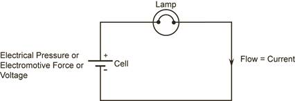
Figure 8.
1. The source of supply is always associated with energy conversion.
(a) Generator ( converts mechanical energy to electrical energy )
(b) Cell or Battery ( converts chemical energy to electrical energy )
The source of supply will provide pressure called Electromotive Force or Voltage.
The symbol for voltage is U.
2. The load is any device that is placed in the electrical circuit that produces an effect when an electric current flows through it. When an electric current flows through an incandescent lamp, the lamp gives off light from heat.
3. The connecting leads or cables complete the circuit. The cable consists of the conductor to carry the current and insulation to prevent leakage. A water pipe must have a bore to carry the water and the pipe material ( e.g. copper ) to prevent leakage.
The simplest analogy of an electric circuit is to consider a hosepipe connected to a tap. The rate of flow of water from the end of the hosepipe will depend upon:
If there are many restrictions, the water will flow out of the hosepipe at a reduced rate.
See Figure 9.
|
Figure 9.
In much the same way, current flows through conductors by means of electric pressure provided by a battery or generating source. This source of electric pressure, electromotive force ( EMF ), provides the energy required to push current through the circuit. It can be referred to as the supply voltage.
Every circuit offers some opposition or restriction to current flow, which is called circuit resistance. The unit of resistance is the Ohm, symbol W, pronounced Omega. At this stage, conductor resistance is ignored and the load resistance is treated as the total opposition to current flow.
For a stable supply voltage, the current ( I ) which flows, is determined by resistance ( R ) of the circuit. There will be a voltage drop across different parts of the circuit and this is called Potential Difference ( PD ).
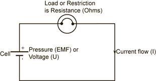
Figure 10
Unlike the hosepipe analogy, the electric circuit requires a “go” and “return” conductor to form a closed loop or complete circuit. These conductors must offer a low resistance path to the flow of current. Most metallic conductors satisfy this requirement.
George Ohm discovered the relationship between, current flowing in a circuit and the pressure applied across that circuit. This became known as Ohm’s Law.
Ohm’s Law states that the current ( I ) flowing through a circuit is directly proportional to the potential difference ( U ), across that circuit, and inversely proportional to the resistance ( R ), of that circuit, provided the temperature remains constant.
|
Now consider any circuit in which you know the values of any two of the three factors - voltage, current and resistance - and you want to find the third. The rule for working the “Magic Triangle” to give the correct formula is as follows:
Place your thumb over the letter in the triangle whose value you want to know - and the formula for calculating that value is given by the two remaining letters.
|
Refer to Figure 11. In this arrangement the resistor value is kept constant whilst the voltage is increased in steps of two volts and current readings are taken.
|
Figure 11.
The following results were obtained from the experiment and plotted in graph form as shown below.
Voltage = I x R
2 = 0.02 x 100
4 = 0.04 x 100
6 = 0.06 x 100
8 = 0.08 x 100
10 = 0.10 x 100
|
Figure 12
The above graph and experiment illustrates, that current flow increases proportionally as the applied voltage is increased.
From the previous exercises it will be noticed that the amount of current that flows in a circuit is directly proportional to the voltage and inversely proportional to the resistance.
With a fairly constant supply of 230 Volts, the load or resistance of the circuit will determine the amount of current that will flow.
One of the basic requirements that a circuit must have is overcurrent protection. This is essential for protection of the cables and accessories in the circuit. A fuse or circuit breaker is used to provide this protection. It is fitted as close to the origin of the circuit as possible to cut off the supply if too much current flows in the circuit. This is called circuit protection.
See Figure 13.
Another basic requirement is that the circuit can be controlled. A switch must be fitted to turn the supply on or off. This is called circuit control.
The principles of circuit protection and circuit control are illustrated in Figure 13.
|
Figure 13.
An open circuit exists, when there is a break in a circuit. This break results in an extremely high resistance in the circuit. This will stop current flow. This value of extremely high resistance is referred to as infinity. It is denoted by the symbol ¥.
Examples: See Figure 14.
|
Figure 14.
Current will flow through the path of least resistance or opposition in a circuit.
A short circuit occurs when the resistance or opposition in a circuit is very low.
Examples: See Figures 15, 15A and 15B.
|
Figure 15.
|
Figure 15A.
|
Figure 15B.
A short circuit usually results in a dangerously high current flowing. A fuse or circuit breaker is the deliberate “weak link” in a circuit. Either will open the circuit when too much current flows.
When an electric current flows in a circuit it can have one or more of the following effects:
The movement of electrons in a circuit, which is the flow of an electric current, causes an increase in the temperature of the load resistance. The huge number of electrons being pushed through the load resistance, results in high friction and collision of these electrons. This generates heat. The amount of heat generated depends upon the type and dimensions of the load resistance wire and the value of current flowing. By changing these variables, a length of resistance wire may be operated at different temperatures to give different effects, e.g. an ordinary light bulb or an electric heater.
See Figure 16.
|
Figure 16.
Whenever a current flows in a conductor a magnetic field is set up around that conductor.
See Figure 17 below.
|
Figure 17.
This magnetic field increases in strength if the current is increased and collapses if the current is switched off. A “current carrying conductor”, wound in the form of a solenoid ( coil ), produces a magnetic field very similar to that of a permanent magnet, but has the advantage in that it can be switched on or off by any switch controlling the circuit current.
The magnetic effect of an electric current is the principle upon which electric bells, relays, moving coil instruments, motors and generators work.
The strength of the magnetic field is directly proportional to the current in the circuit. The “clamp on” type ammeter measures the strength of the magnetic field and produces a reading in Amps.
When an electric current flows through an electrolyte ( conducting liquid / paste ), this electrolyte is separated into chemical parts. The two conductors, which make contact with the electrolyte, are called the anode ( positive plate ) and the cathode ( negative plate ).
An anode or cathode of dissimilar metals placed in an electrolyte can react chemically and produce an EMF. When a load is connected across the anode and cathode, a current will flow in the circuit.
The chemical effect of an electric current is the principle upon which electric cells operate.
See Figure 18.
|
Figure 18.
A unit is what we use to indicate the measurement of a quantity. For example, the unit of current is the Ampere. The unit of length could be the Inch or the Metre. However, the Metre is the SI unit of length.
In order that we all work to a common standard, an international system is used. It is known as the SI system ( System International ). This system is used throughout the course. A number of prefixes will be used e.g. microamps and milliamps, millivolts and kilovolts, kilohms and megohms.
Multiplying Power
Prefix Symbol Factor Index
mega* M 1 000 000 (106)
kilo* k 1 000 (103)
hecto h 100 (102)
deca da 10 (101)
deci d 0.1 (10-1)
centi c 0.01 (10-2)
milli* m 0.001 (10-3)
micro* m 0.000 001 (10-6)
nano n 0.000 000 001 (10-9)
pico p 0.000 000 000 001 (10-12)
* denotes frequently used prefixes in the Electrical Trade.
To convert amps to milliamps multiply by 1,000 (103)
To convert amps to microamps multiply by 1,000,000 (106)
To convert milliamps to amps multiply by 0.001 (10-3)
To convert microamps to milliamps multiply by 0.001 (10-3)
Convert the following:
1. 13,000,000 Ohms to megohms
2. 500,000 Ohms to megohms
3. 0.5 Volts to millivolts
4. 100 Volts to millivolts
5. 15,000 Volts to kilovolts
6. 0.4 kilovolts to Volts
7. 600 milliamps to Amps
8. 0.03 Amps to milliamps
1. 1,000,000 Ohms = 1 megohm = 1MW
13,000,000 Ohms = 13 megohms = 13MW
2. 500,000 Ohms = 0.5 megohms = 0.5MW
3. 1 Volt = 1000 millivolts = 1000mV
0.5 Volts = 500 millivolts = 500mV
4. 100 Volts = 100,000 millivolts = 100,000mV
5. 1,000 Volts = 1 kilovolt = 1kV
15,000 Volts = 15 kilovolts = 15kV
6. 1 kilovolt = 1,000 Volts = 1000V
0.4 kilovolts = 400 Volts = 400V
7. 1,000 milliamps = 1 Amp = 1A
600 milliamps = 0.6 Amps = 0.6A
8. 1 Amp = 1,000 milliamps = 1000mA
0.1 Amps = 100 milliamps = 100mA
0.01 Amps = 10 milliamps = 10mA
0.03 Amps = 30 milliamps = 30mA
An ammeter is a device used to measure current flowing through a circuit or part of a circuit. It indicates, in terms of amperes, the number of coulombs passing a given point in a circuit, in one second. The ammeter shown in Figure 1 has a Full Scale Deflection ( FSD ) of 40A.
 |
Figure 19.
The ammeter must be physically connected into the circuit. It can then measure all the electrons passing through it.
The ammeter in Figure 20 is said to be in series with the resistor or load.
|
Figure 20.
Note: The ammeter may be damaged if incorrectly connected.
The positive and negative terminals of a direct current ( DC ) meter must be connected correctly as shown in Figure 2. This is referred to as correct polarity. It allows the meter to read up-scale. Reversed polarity causes the meter to read down scale. This forces the pointer against the stop at the left, which may damage the meter.
The current required to be measured should be estimated. Select a meter having a FSD a good deal higher than the estimated current. Any current value in excess of the FSD of the meter will not only fail to register properly on the scale, but will probably cause serious damage to the meter.
On the other hand, any current value very low in relation to the FSD will not cause the pointer to move. An accurate reading cannot be obtained in this situation. The useful range of any meter never, in fact, extends right down to zero on its scale. It only goes down to the point at which readings can be distinguished from zero with reasonable accuracy.
Apprentices to install an ammeter into a circuit as shown in Figure 21 and measure the current.
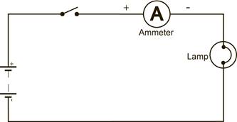
Figure 21.
A voltmeter measures electromotive force ( EMF ) or potential difference ( PD ). It must be connected across the supply or load resistance in order to record the voltage. That is, it must be connected in parallel with the component as in Figure 22.
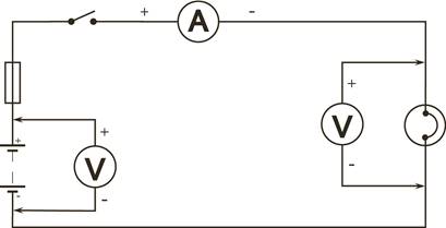
Figure 22.
Note: The voltmeter may be damaged if incorrectly connected.
A DC voltmeter ( analogue type ) must be connected with the correct polarity for the meter to read up scale. When selecting a meter to measure voltage, choose one having a maximum range a good deal higher than the value of any voltage you expect to be measuring. The reason for this is that a voltage in excess of the maximum rated value of the meter will not only fail to register properly on the scale, but will probably cause serious damage to the meter.
Measure the voltage at the supply terminals and the potential difference across the load of the circuit shown in Figure 23.
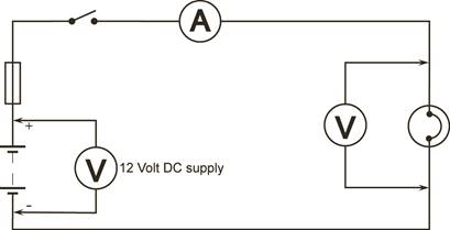
Figure 23.
An ohmmeter is used to check the electrical continuity of components and to measure their resistance. It is powered by its own internal battery. A typical ohmmeter is depicted in Figure 24. Before connecting an ohmmeter in circuit it is important to ensure that:
|
Figure 24.
Measurements are taken by connecting the meter across the unknown resistor as shown in Figure 725. It is important to select the most suitable scale for the resistance under test. The current flowing through the unknown resistance will cause the pointer to deflect. This deflection, when multiplied by the scale factor ( range selection switch setting ), will give the value of the resistance being measured. The ohmmeter scale is normally non-linear with zero on the opposite side of the scale to that used for voltage and current measurement.
|
Figure 25.
A multimeter is an instrument that can be set or programmed to measure voltage, current or resistance. Most modern multimeters have a number of other functions such as diode checking and capacitance measurement. These instruments can measure Direct Current ( DC ) or Alternating Current ( AC ) over several ranges.
The main types are:
Analogue Type Digital Type
Features: Features:
Analogue Display Digital Display
Manual Range Setting Range Setting Automatic / Manual
It is important that the instruction manual supplied with a meter is studied prior to operation of the meter. These manuals normally contain warnings and information, which must be followed to ensure safe operation and retain the meter in a safe condition.
All materials have some resistance to the flow of an electric current. In general, the term resistordescribes a conductor specially chosen for its resistive properties.
Resistors are the most commonly used electronic components. They are made in a variety of ways to suit particular types of application. They are usually manufactured as either carbon composition or carbon film. In both cases the base resistive material is carbon. The general appearance is of a small cylinder with leads protruding from each end.
The value of the resistor and its tolerance may be marked on the body of the component. This may be done either by direct numerical indication or by using a standard colour code. The coloured bands are located on the component towards one end. If the resistor is turned so that this end is towards the left, then the bands are read from left to right, See Figure 26.
|
Figure 26.
1st Band Colour - 1st Digit
2nd Band Colour - 2nd Digit
3rd Band Colour - Multiplier ( in effect the number of zeros )
4th Band Colour - Tolerance
Black 0
Brown 1
Red 2
Orange 3
Yellow 4
Green 5
Blue 6
Violet 7
Grey 8
White 9
The fourth resistor colour band indicates the resistor tolerance. This is commonly gold or silver, indicating a tolerance of 5% or 10% respectively. Sometimes the coloured bands are not clearly oriented towards one end. In this case, first identify the tolerance band and turn the resistor so that this is to the right. Then read the colour code as described below.
The tolerance band indicates the maximum tolerance variation in the declared value of resistance. Thus a 100 W resistor with a 5% tolerance will have a value of somewhere between 95 W and 105 W, since 5% of 100 W is 5 W.
If no fourth band exists this indicates a tolerance of + / - 20%.
Tolerance indicators Gold Silver No band
5% 10% 20%
|
Figure 27.
If a resistor has colour code bands of blue, grey, red, gold, what is its ohmic value?
Solution:
Blue = 6 1st Digit
Grey = 8 2nd Digit
Red = 2 Number of zeros
Gold = 5% Tolerance
Resistor value is 6,800 W with a 5% tolerance
This resistor will have an ohmic value between 6,460 and 7,140 ohms.
Practice reading the colour code of different values of resistors and calculate the tolerance range.
Mnemonic to Remember the Resistor Colour Code:
Better Be Right Or Your Great Big Venture Goes Wrong
It is difficult to manufacture small electronic resistors to exact values by mass production methods. This is not a disadvantage as in most electronic circuits the values of the resistors is not critical. Manufacturers produce a limited range of PREFERRED resistance values rather than an overwhelming number of individual resistance values. Therefore, in electronics we use the preferred value closest to the actual value required.
A resistor with a preferred value of 100 W and a 10% tolerance could actually have any value between 90 W and 110 W. The next largest preferred value, which would give the maximum possible range of resistance values without too much overlap, would be 120 W. This could have any value between 108 W and 132 W.
Table 1 indicates the preferred values between 10 W and 82 W, but the larger values, which are manufactured, can be obtained by multiplying these preferred values by a factor of 10.
47 W, ( 47 x 10 ) = 470 W = 470R
470 W, ( 470 x 10 ) = 4,700 W = 4.7k
4,700 W, ( 4,700 x 10 ) = 47,000 W = 47k
47,000 W ( 47,000 x 10 ) = 470,000 W = 470k
470,000 W ( 470,000 x 10 ) = 4,700,000 W = 4.7M
For a number of reasons the decimal point is not used. Take the 4·7k resistor, this may be written 4k7. The k is positioned so that it indicates where the decimal point should be. The R and M can be used in the same manner as in the examples below.
Examples:
18 W = 18R
2·7 kW = 2k7 (2,700R)
39 kW = 39k (39,000R)
5·6 MW = 5M6 (5,600,000R)
82 MW = 82M (82,000,000R)
Rated Value Possible Range of Values
in Ohms in Ohms
10 9.0 to 11.0
12 10.8 to 13.2
15 13.5 to 16.5
18 16.2 to 19.8
22 19.8 to 24.2
27 24.3 to 29.7
33 29.7 to 36.3
39 35.1 to 42.9
47 42.3 to 51.7
56 50.4 to 61.6
68 61.2 to 74.8
82 73.8 to 90.2
and so on in multiples of 10
Table 1
Source: http://local.ecollege.ie/Content/APPRENTICE/liu/electrical_notes/LL214.doc
Web site to visit: http://local.ecollege.ie/
Author of the text: indicated on the source document of the above text
If you are the author of the text above and you not agree to share your knowledge for teaching, research, scholarship (for fair use as indicated in the United States copyrigh low) please send us an e-mail and we will remove your text quickly. Fair use is a limitation and exception to the exclusive right granted by copyright law to the author of a creative work. In United States copyright law, fair use is a doctrine that permits limited use of copyrighted material without acquiring permission from the rights holders. Examples of fair use include commentary, search engines, criticism, news reporting, research, teaching, library archiving and scholarship. It provides for the legal, unlicensed citation or incorporation of copyrighted material in another author's work under a four-factor balancing test. (source: http://en.wikipedia.org/wiki/Fair_use)
The information of medicine and health contained in the site are of a general nature and purpose which is purely informative and for this reason may not replace in any case, the council of a doctor or a qualified entity legally to the profession.
The texts are the property of their respective authors and we thank them for giving us the opportunity to share for free to students, teachers and users of the Web their texts will used only for illustrative educational and scientific purposes only.
All the information in our site are given for nonprofit educational purposes