
SECTION 3 GENERAL DESIGN REQUIREMENTS
3.1.1 Design Objective – The objective of design is the achievement of an acceptable probability that structures will perform satisfactorily for the intended purpose during the design life. With an appropriate degree of safety, they should sustain all the loads and deformations during construction and use and have adequate resistance to accidental loads and fire.
3.1.2 Methods of Design
3.1.2.1 Structure and its elements shall normally be designed by the Limit State Method. Account should be taken of accepted theories, experimental information and experience and the need to design for durability. Calculations alone may not produce safe, serviceable and durable structures. Suitable materials, quality control, adequate detailing and good supervision are equally important.
3.1.2.2 Where the Limit States Method can not be conveniently adopted; Working Stress Method (Section 11) may also be used.
3.1.3 Design Process – Structural design, including design for durability, construction and use should be considered as a whole. The realization of design objectives requires compliance with clearly defined standards for materials, fabrication, erection and inservice maintenance.
3.2 Loads and Forces
3.2.1 For the purpose of designing any element, member or a structure, the following loads (actions) and their effects shall be taken into account, where applicable, with partial safety factors and combinations (5.3.3).
3.2.1.1 Dead loads should be assumed in design as specified in IS: 875 (Part 1).
3.2.1.2 Imposed loads for different types of occupancy and function of structures shall be taken as recommended in IS: 875 (Part 2). Imposed loads arising from equipment, such as cranes and machines should be assumed in design as per manufacturers/suppliers data (3.5.4). Snow load shall be taken as per IS: 875 (Part 4).
3.2.1.3 Wind loads on structures shall be taken as per the recommendations of IS:
875 (Part 3).
3.2.1.4 Earthquake loads shall be assumed as per the recommendations of IS: 1893.
3.2.1.5 The erection loads and temperature effects shall be considered as specified in 3.3 and 3.4 respectively.
3.3 Erection Loads
3.3.1 All loads required to be carried by the structure or any part of it due to storage or positioning of construction material and erection equipment, including all loads due to operation of such equipment shall be considered as erection loads. Proper provision shall be made, including temporary bracings, to take care of all stresses developed during erection. Dead load, wind load and also such parts of the live load as would be imposed on the structure during the period of erection shall be taken as acting together with the erection loads. The structure as a whole and all parts of the structure in conjunction with the temporary bracing’s shall be capable of sustaining these loads during erection.
3.4 Temperature Effects
3.4.1 Expansion and contraction due to changes in temperature of the members and elements of a structure shall be considered and adequate provision made for such effect.
3.4.2 The temperature range varies for different localities and under different diurnal and seasonal conditions. The absolute maximum and minimum temperatures, which may be expected in different localities of the country, are indicated in the maps of India given in Appendices A and B respectively. These may be used for guidance in assessing the maximum variations of temperature for which provision for expansion and contraction has to be made in the structure.
3.4.3 The temperatures indicated on the maps in Appendices A and B are the air temperatures in the shade. The range of variation in temperature of the building materials may be appreciably greater or lesser than the variation of air temperature and is influenced by the condition of exposure and the rate at which the materials composing the structure absorb or radiate heat. This difference in temperature variations of the material and air should be given due consideration. The effect of differential temperature within an element or member, due to part exposure to direct sunlight may also be considered.
3.4.4 The co-efficient of thermal expansion for steel is as given in Section 2.2.4.1(e).
3.5 Load Combinations
3.5.1 Load combinations for design purposes shall be those that produce maximum forces and effects and consequently maximum stresses and deformations. The following combination of loads with appropriate load factors as given in Table 5.1 may be considered.
Note: In the case of structures supporting cranes, imposed loads shall include the crane effects as given in 3.5.4.
3.5.2 Wind load and earthquake loads shall not be assumed to act simultaneously. The effect of both the forces shall be considered separately.
3.5.3 The effect of cranes to be considered under imposed loads shall include the vertical loads, eccentricity effects induced by the vertical loads, impact factors, lateral (surge) and the longitudinal (horizontal) thrusts, acting across and along the crane rail respectively.
3.5.4 The crane loads to be considered shall be as indicated by the customer. In the absence of any specific indications, the load combinations shall be as per IS: 875 (Part 2).
3.5.5 While investigating the effect of earthquake forces, the resulting effect from dead loads of all cranes parked in each bay positioned to cause maximum effect shall be considered.
3.5.6 The crane runway girders supporting bumpers shall be checked for bumper impact loads also.
3.5.7 Stresses developed due to secondary effects such as handling; erection, temperature and settlement of foundations shall be appropriately added to the stresses calculated from the combination of loads stated in 3.5.1 with appropriate partial safety factors.
3.6 Geometrical Properties
3.6.1 General - The geometrical properties of the gross and the effective cross sections of a member or part thereof, shall be calculated on the following basis:
i) The sectional area in excess of effective plate width in case of slender sections (3.7).
ii) The sectional areas of all holes in the section except those for parts in compression. In case of punched holes, hole size 2 mm in excess of the actual diameter may be deducted.
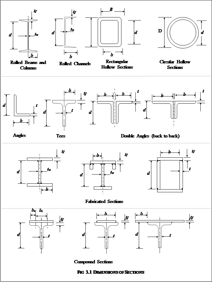
3.7 Classification of Cross sections
3.7.1 Basis - The plate elements of a cross section may buckle locally due to compressive stresses. The local buckling can be avoided before the limit state is achieved by limiting the width to thickness ratio of each element of a cross-section, subjected to compression due to axial force, moment or shear.
3.7.1.1 When plastic analysis is used, the members shall be capable of forming plastic hinges with sufficient rotation capacity (ductility) without local buckling to enable the redistribution of bending moment required before formation of the failure mechanism.
3.7.1.2 When elastic analysis is used, the member shall be capable of developing the yield stress under compression without local buckling.
3.7.2 On the above basis, four classes of sections are defined as follows:
a) Plastic - Cross sections, which can develop plastic hinges and have the rotation capacity required for failure of the structure by formation of a plastic mechanism.
b) Compact - Cross sections, which can develop plastic moment of resistance, but have inadequate plastic hinge rotation capacity for formation of a plastic mechanism.
c) Semi-Compact - Cross sections, in which the extreme fibre in compression can reach, yield stress, but cannot develop the plastic moment of resistance, due to local buckling.
d) Slender - Cross sections in which the elements buckle locally even before reaching yield stress.
In such cases, the effective sections for design shall be calculated by deducting width of the compression plate element in excess of the semi-compact section limit.
a) Internal elements are elements attached along both longitudinal edges to other elements or to longitudinal stiffeners connected at suitable intervals to transverse stiffeners.
b) Outside elements or Outstands are elements attached along only one of the longitudinal edges to an adjacent element, the other edge being free to displace out of plane.
c) Tapered elements may be treated as flat elements having average thickness as defined in section hand book (SP: 6).
The design of slender compression element considering the strength beyond elastic local buckling of element is outside the scope of this code. Reference may be made to IS: 801 for such design provisions. The design of slender web elements may be as given in 8.2.1.1 for flexure and 8.4.2.2 for shear.
When different elements of a cross section fall under different classification, the section shall be classified as governed by the critical element.
The limiting width to thickness ratios of elements for different classifications of sections are given in Table 3.1.
3.7.3 Compound elements in built-up section - In case of compound elements consisting of two or more elements bolted or welded together following width to thickness ratio should be considered (Fig 3.1).
a) Outstand of compound element compared to the thickness of the original element of the rolled section.
b) The internal width of each added plate between the lines of welds or fasteners connecting it to the original section compared to its own thickness.
c) Any outstand of the added plates beyond the line of welds or fasteners connecting it to original section compared to its own thickness.
3.8 Maximum Effective Slenderness Ratio
3.8.1 The maximum effective slenderness ratio, KL/r, values of a beam, strut or tension member shall not exceed those given in Table 3.2. In this KL is the effective length of the member and r is appropriate radius of gyration based on the effective section as defined in 3.6.1.
3.9 Resistance to Horizontal Forces
3.9.1 In designing the steel frame work of a building, provision shall be made (by adequate moment connections or by a system of bracing using rods and angles etc.,) to effectively transmit to the foundations all the horizontal forces, giving due allowance for the stiffening effect of the walls and floors, where applicable.
(Section 3.7.2)
Compression element |
Ratio |
Class of Section |
||||||
Class 1 |
Class 2 |
Class 3Semi-Compact |
||||||
Outstanding element of compression flange Internal element of compression flange |
Rolled section |
b/tf |
9.4e |
10.5e |
15.7e |
|||
Welded section |
b/ tf |
8.4e |
9.4e |
13.6e |
||||
Compression due to bending |
b/ tf |
29.3e |
33.5e |
42e |
||||
Axial compression |
b/ tf |
Not applicable |
||||||
Web of an I-H-or box section c |
Neutral axis at mid-depth |
d/tw |
83.9e |
104.8e |
125.9e |
|||
Generally |
If r1 is negative: |
d/tw |
|
|
|
|||
If r2 is negative: |
d/tw |
|
||||||
Axial compression |
d/tw |
Not applicable |
||||||
Web of a channel |
d/tw |
42e |
42e |
42e |
||||
Angle, compression due to bending |
b/t |
9.4e |
10.5e |
15.7e |
||||
Single angle, or double angles with the components separated, axial compression (All three criteria should be satisfied) |
b/t |
Not applicable |
15.7e |
|||||
Outstanding leg of an angle in contact back-to-back in a double angle member |
d/t |
9.4e |
10.5e |
15.7e |
||||
Outstanding leg of an angle with its back in continuous contact with another component |
||||||||
Circular tube subjected to moment or axial compression |
CHS or built by welding |
D/t |
44e2 |
62.7e2 |
88e2 |
|||
Stem of a T-section, rolled or cut from a rolled I-or H-section |
D/tf |
8.4e |
9.4e |
18.9e |
||||
Note 1: Section having elements which exceeds semi-compact limits are to be taken as slender cross sections
|
||||||||
(Section 3.8.1)
Sl.No. |
Member |
Maximum Effective Slenderness Ratio (KL/r) |
1 |
A member carrying compressive loads resulting from dead loads and imposed loads |
180 |
2 |
A tension member in which a reversal of direct stress occurs due to loads other than wind or seismic forces |
180 |
3 |
A member subjected to compression forces resulting only from combination with wind/earthquake actions, provided the deformation of such member does not adversely affect the stress in any part of the structure |
250 |
4 |
Compression flange of a beam against lateral torsional buckling |
300 |
5 |
A member normally acting as a tie in a roof truss or a bracing system but not considered effective when subject to possible reversal of stress resulting from the action of wind or earthquake forces1 |
350 |
6 |
Members always under tension1 (other than pretensioned members) |
400 |
1 Tension members, such as bracing’s, pretensioned to avoid sag, need not satisfy the maximum slenderness ratio limits.
3.9.2 When the walls, or walls and floors and/or roofs are capable of effectively transmitting all the horizontal forces directly to the foundations, the structural steel framework may be designed without considering the effect of wind or earthquake.
3.9.3 Wind and earthquake forces are reversible and therefore call for rigidity and strength under force reversal in both longitudinal and transverse directions. To resist torsional effects of wind and earthquake forces, bracing’s in plan should be provided and integrally connected with the longitudinal and transverse bracing’s, to impart adequate torsional resistance to the structure.
3.9.3.1 In shed type steel mill buildings, adequate bracing’s shall be provided to transfer the wind or earthquake loads from their points of action to the appropriate supporting members. Where the connections to the interior columns or frames are designed such that the wind or earthquake loads will not be transferred to the interior columns, the exterior columns or frames shall be designed to resist the total wind or earthquake loads. Where the connections to the interior columns and frames are designed such that the wind or earthquake effects are transferred to the interior columns also, and where adequate rigid diaphragm action can be mobilized as in the case of the cast-in place RC slab, both exterior and interior columns and frames may be designed on the assumption that the wind or earthquake load is divided among them in proportion to their relative stiffenesses. Columns also should be designed to withstand the net uplifting effect caused by excessive wind or earthquake. Additional axial forces arising in adjacent columns due to the vertical component of bracing’s or due to frame action shall also be accounted for.
3.9.3.2 Earthquake forces are proportional to the seismic mass as defined in IS: 1893. Earthquake forces should be applied at the centre of gravity of all such components of mass and their transfer to the foundation should be ensured. Other construction details, stipulated in IS: 4326 should also be followed.
3.9.3.3 In buildings where high-speed travelling cranes are supported or where a building or structure is otherwise subjected to vibration or sway, triangulated bracing or rigid portal systems shall be provided to reduce the vibration or sway to an acceptable minimum.
3.9.4 Foundations – The foundations of a building or other structures shall be designed to provide the rigidity and strength that has been assumed in the analysis and design of the superstructure.
3.9.5 Eccentrically Placed Walls – Where a wall is placed eccentrically upon the flange of a supporting steel beam, the beam and its connections shall be designed for torsion, unless the beam is restrained laterally in such a way as to prevent the twisting of the beam.
3.10 Expansion Joints
3.10.1 In view of the large number of factors involved in deciding the location, spacing and nature of expansion joints the decision regarding, provision of expansion joints, can be made at the discretion of the designer.
3.10.2 Structures in which marked changes in plan dimensions take place abruptly, shall be provided with expansion joints at the section where such changes occur. Expansion joints shall be so provided that, the necessary movement occurs with minimum resistance at the joint. The gap at the expansion joint should be such that
3.10.3 The details as to the length of a structure where expansion joints have to be provided may be determined after taking into consideration various factors such as temperature, exposure to weather and structural design. The following provisions are given as general guidance.
|
|
|
|
|
|
|
|
|
|
|
|
|
|
![]()
|
|
|
|
|
|
|
|
|
|
|
|
|
|
|
|
|
|
|
|
|
|
|
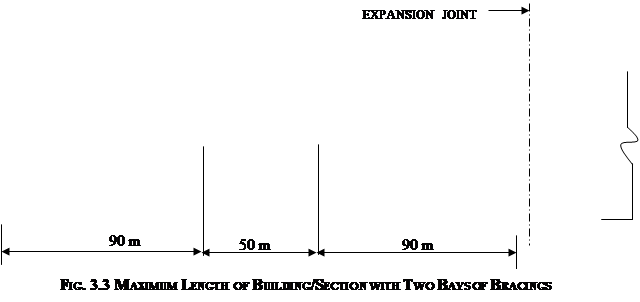
FIG. 3.2 MAXIMUM LENGTH OF BUILDING WITH ONE BAY OF BRACING
Source: http://www.buildnova.com/buildnovav3/IS800/IS800SECTION3.doc
Web site to visit: http://www.buildnova.com
Author of the text: indicated on the source document of the above text
If you are the author of the text above and you not agree to share your knowledge for teaching, research, scholarship (for fair use as indicated in the United States copyrigh low) please send us an e-mail and we will remove your text quickly. Fair use is a limitation and exception to the exclusive right granted by copyright law to the author of a creative work. In United States copyright law, fair use is a doctrine that permits limited use of copyrighted material without acquiring permission from the rights holders. Examples of fair use include commentary, search engines, criticism, news reporting, research, teaching, library archiving and scholarship. It provides for the legal, unlicensed citation or incorporation of copyrighted material in another author's work under a four-factor balancing test. (source: http://en.wikipedia.org/wiki/Fair_use)
The information of medicine and health contained in the site are of a general nature and purpose which is purely informative and for this reason may not replace in any case, the council of a doctor or a qualified entity legally to the profession.
The texts are the property of their respective authors and we thank them for giving us the opportunity to share for free to students, teachers and users of the Web their texts will used only for illustrative educational and scientific purposes only.
All the information in our site are given for nonprofit educational purposes