( Immersed Bodies)
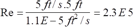
In general, a body immersed in a flow will experience both externally applied forces and moments as a result of the flow about its external surfaces. The typical terminology and designation of these forces and moments are given in the diagram shown below.
The orientation of the axis for the drag force is typically along the principal body axis, although in certain applications, this axis is aligned with the principal axis of the free stream approach velocity U.
Since in many cases the drag force is aligned with the principal axis of the body shape and not necessarily aligned with the approaching wind vector. Review all data carefully to determine which coordinate system is being used: body axis coordinate system or a wind axis coordinate system.
These externally applied forces and moments are generally a function of
a. Body geometry
b. Body orientation
c. Flow conditions
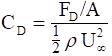
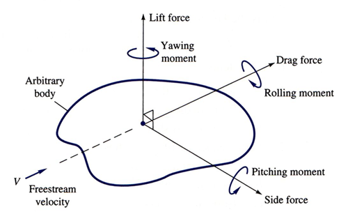
These forces and moments are also generally expressed in the form of a non-dimensional force/moment coefficient, e.g. the drag coefficient: |
|
It is noted that it is common to see one of three reference areas used depending on the application:
1. Frontal (projected) area: Used for thick, stubby, non-aerodynamic shapes, e.g., buildings, cars, etc.
2. Planform (top view, projected) area: Used for flat, thin shapes, e.g., wings, hydrofoils, etc.
3. Wetted area: The total area in contact with the fluid. Used for surface ships, barges, etc.
The previous, flat plate boundary layer results considered only the contribution of viscous surface friction to drag forces on a body. However, a second major (and usually dominant) factor is pressure or form drag.
Pressure drag is drag due to the integrated surface pressure distribution over the body. Therefore, in general, the total drag coefficient of a body can be expressed as
![]()
or
Which factor, pressure or friction drag, dominates depends largely on the aerodynamics (streamlining) of the shape and to a lesser extent on the flow conditions.
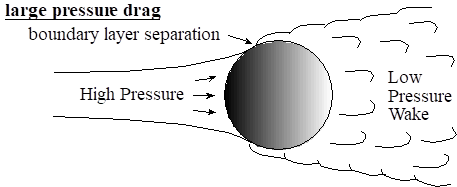
Typically, the most important factor in the magnitude and significance of pressure or form drag is the boundary layer separation and resulting low pressure wake region associated with flow around non - aerodynamic shapes.
Consider the two shapes shown below:
Non-aerodynamic shape
Aerodynamic shape
low pressure drag no separated flow region
![]()
The flow around the streamlined airfoil remains attached, producing no boundary layer separation and comparatively small pressure drag. However, the flow around the less aerodynamic circular cylinder separates, resulting in a region of high surface pressure on the front side and low surface pressure on the back side and thus significant pressure drag.
This effect is shown very graphically in the following figures from the text.
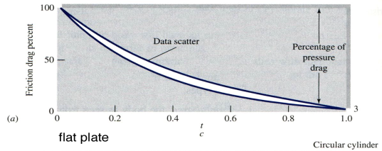
Fig. 7.12 Drag of a 2-D, streamlined cylinder
The previous figure shows the effect of streamlining and aerodynamics on the relative importance of friction and pressure drag.
While for a thin flat plate (t/c = 0) all the drag is due to friction with no pressure drag, for a circular cylinder (t/c = 1) only 3% of the drag is due to friction with 97% due to pressure. Likewise, for most bluff, non-aerodynamic bodies, pressure (also referred to as form drag) is the dominant contributor to the total drag.
However, the magnitude of the pressure (and therefore the total) drag can also be changed by reducing the size of the low pressure wake region, even for non-aerodynamic shapes.
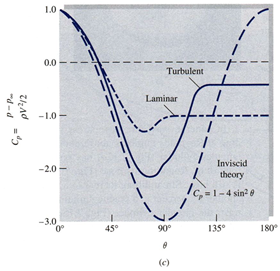
One way to do this is to change the flow conditions from laminar to turbulent. This is illustrated in the following figures from the text for a circular cylinder.
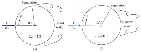
Fig. 7.13 Circular cylinder with (a) laminar separation and (b) turbulent separation
Note that for the cylinder on the left, the flow is laminar, boundary layer separation occurs at 82o, and the CD is 1.2.
However, for the cylinder on the right, the flow is turbulent and separation is delayed (occurs at 120o). The drag coefficient CD is 0.3, a factor of 4 reduction due to a smaller wake region and reduced pressure drag.
It should also be pointed out that the friction drag for the cylinder on the right is probably greater (turbulent flow conditions) than for the cylinder on the left (laminar flow conditions).
However, since pressure drag dominates, the net result is a significant reduction in the total drag. |
|
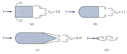
Finally, the effect of streamlining on total drag is shown very graphically with the sequence of modifications in Fig. 7.15.
Two observations can be made: (1) As body shape changes from a bluff body with fixed points of separation to a more aerodynamic shape, the effect of pressure drag and the drag coefficient will decrease. |
|
Fig. 7.15 The effect of streamlining on total drag
(2) The addition of surface area from (a) to (b) and (b) to (c) increases the friction drag, however, since pressure drag dominates, the net result is a reduction in the drag force and CD and the total drag force.
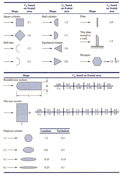
The final two figures show results for the drag coefficient for two and three dimensional shapes with various geometries.
Table 7.2 CD for Two-Dimensional Bodies at Re ≥ 104
First note that all values in Table 7.2 are for 2-D geometries, that is, the bodies are very long (compared to the cross-section dimensions) in the dimension Key Point: Non – aerodynamic shapes with fixed points of separations (sharp corners) have a single value of CD, irrespective of the value of the Reynolds number, e.g. square cylinder, half-tube, etc. Aerodynamic shapes generally have a reduction in CD for a change from laminar to turbulent flow as a result of the shift in the point of boundary layer separation, e.g. elliptical cylinder. |
|
Table 7.3 Drag of three-dimensional bodies at Re ≥ 104
The geometries in Table 7.3 are all 3-D and thus are finite perpendicular to the page. Similar to the results from the previous table, bluff body geometries with fixed points of separation have a single CD, whereas aerodynamic shapes such as slender bodies of revolution have individual values of CD for laminar and turbulent flow.
In summary, one must remember that broad generalizations such as saying that turbulent flow always increases drag, drag coefficients always depend on Reynolds number, or increasing surface area increases drag are not always valid. One must consider carefully all effects (viscous and pressure drag) due to changing flow conditions and geometry.
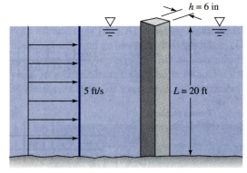
Example:
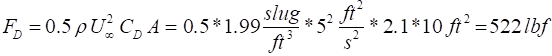
A square 6-in piling is acted on by a water flow of 5 ft/s that is 20 ft deep. Estimate the maximum bending stress exerted by the flow on the bottom of the piling. Water: r = 1.99 slugs/ft3 |
|
Assume that the piling can be treated as 2-D and thus end effects are negligible.
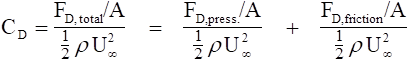
Thus for a width of 0.5 ft, we obtain:
|
In this range, Table 7.2 applies for 2-D bodies and we read CD = 2 .1. The frontal area is A = 20*0.5 = 10 ft2 |
For uniform flow, the drag should be uniformly distributed over the total length with the net drag located at the mid-point of the piling.
Thus, relative to the bottom of the piling, the bending moment is given by
Mo = F * 0.5 L = 522 lbf* 10 ft = 5220 ft-lbf
From strength of materials, we can write
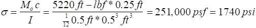
where c = distance to the neutral axis, I = moment of inertia = b h3/12
Question: Since pressure acts on the piling and increases with increasing depth, why wasn’t a pressure load considered?
Answer: Static pressure does act on the piling, but it acts uniformly around the piling at every depth and thus cancels. Dynamic pressure is considered in the drag coefficients of Tables 7.2 and 7.3 and does not have to be accounted for separately.
Source: http://www.eng.auburn.edu/~tplacek/courses/2610/samba/CHEN2610FacultyCh7b.doc
Web site to visit: http://www.eng.auburn.edu/
Author of the text: indicated on the source document of the above text
If you are the author of the text above and you not agree to share your knowledge for teaching, research, scholarship (for fair use as indicated in the United States copyrigh low) please send us an e-mail and we will remove your text quickly. Fair use is a limitation and exception to the exclusive right granted by copyright law to the author of a creative work. In United States copyright law, fair use is a doctrine that permits limited use of copyrighted material without acquiring permission from the rights holders. Examples of fair use include commentary, search engines, criticism, news reporting, research, teaching, library archiving and scholarship. It provides for the legal, unlicensed citation or incorporation of copyrighted material in another author's work under a four-factor balancing test. (source: http://en.wikipedia.org/wiki/Fair_use)
The information of medicine and health contained in the site are of a general nature and purpose which is purely informative and for this reason may not replace in any case, the council of a doctor or a qualified entity legally to the profession.
The texts are the property of their respective authors and we thank them for giving us the opportunity to share for free to students, teachers and users of the Web their texts will used only for illustrative educational and scientific purposes only.
All the information in our site are given for nonprofit educational purposes