
The critical areas of stress of mating threads are:
For steels of up to 100,000 psi ultimate tensile strength, the tensile stress area of the bolt thread At is
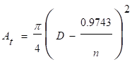
where
D = basic major diameter of the thread (in)
n = number of threads per inch
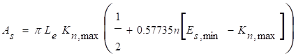
For steels of over 100,000 psi ultimate tensile strength, the tensile stress area of the bolt thread is

where
Es,min = minimum pitch diameter of external thread (in)
The shear area of the external thread (bolt), which depends principally on the minor diameter of the tapped hole, is
![]()
where
Kn,max = maximum minor diameter of internal thread (in)
Le = fastener engagement length (in)
The shear area of the internal thread (hole), which depends principally on the major diameter of the external thread, is
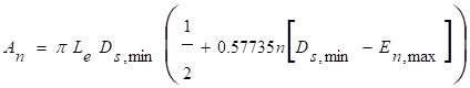
where
Ds,min = minimum major diameter of external thread (in)
En,max = maximum pitch diameter of internal thread (in)
If failure of a threaded assembly should occur, it is preferable for the bolt to break rather than have either the external or internal thread strip because the failure is much easier to detect. In other words, the length of engagement of mating threads should be sufficient to carry the full load necessary to break the screw without the threads stripping.
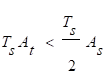
If mating internal and external threads are manufactured of materials having equal tensile strengths, then to prevent stripping of the external thread, the length of engagement should be not less than
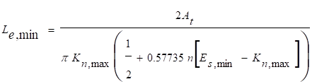
This is equivalent to saying that the shear area must be at least twice the tensile area in order to ensure that stripping of the thread does not occur. (This value is slightly larger than required and thus provides a small factor of safety against stripping.)
If the internal thread is made of material of lower strength than the external thread, stripping of the internal thread may take place before the screw breaks. To determine whether this condition exists, it is necessary to calculate the factor J for the relative strength of the external and internal threads where

where
Ts = tensile strength of the external thread (bolt) material (psi)
Tn = tensile strength of the internal thread (hole) material (psi).
If the factor J is less than or equal to 1, the length of engagement is adequate to prevent stripping of the internal thread. If J is greater than 1, the required length of engagement Q to prevent stripping of the internal thread is obtained by multiplying the minimum length of engagement Le,min by J.
![]()
For a bolted joint with a tapped hole, if the material of tapped hole has lower strength than the bolt, the thread engagement length should be at least equal to Q in order to prevent the stripping of internal thread before the failure of bolt. If the thread engagement length is less then Q, the magnitude of the bolt preload must be reduced.
Equivalently, there are three failures to consider:
For the bolt to break before the threads strip, the following two conditions must exist
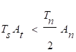
If the bolt does not break before the threads strip, then the threads will strip at the root of the bolt teeth if
![]()
Otherwise, the threads will strip at the roots of the nut threads.
The force F required to either strip the threads of a bolt or nut or break the bolt is
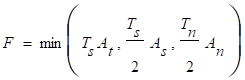 .
.
High preload tension increases joint strength, creates friction between parts to resist shear, and improves the fatigue resistance of bolted connections. Bolt preload in joints should be high enough to maintain joint members in contact and in compression. Loss of compression in a joint may result in loosening of fasteners under conditions of cyclic loading, and reduction of fastener fatigue life.
The preload should be set to avoid permanent deformation in the bolt. The recommended maximum preload P0 is
![]()
where
Sp,s = proof strength of bolt (psi)
cu = 0.75 for reusable connections, 0.9 for permanent connections.
The proof strength is the stress that can be tolerated without any permanent deformation and can be approximated by 85% of the yield strength.
Once the required preload has been determined, one of the best ways to be sure that a bolt is properly tensioned is to measure its tension directly with a strain gage. The choice of method of tensioning should be based on the required accuracy and relative costs. The accuracy of various bolt preload application methods has been tabulated in literature. Examples are shown in Table 1 and Table 2. Significant differences in recommended values can be seen.
Table 1 Accuracy of bolt preload application methods [1]
Method |
Accuracy |
By feel |
± 35% |
Torque wrench |
± 25% |
Turn-of-nut |
± 15% |
Preload indicating washer |
± 10% |
Strain gages |
± 1% |
Computer-controlled wrench |
|
below yield (turn-of-nut) |
± 15% |
yield-point sensing |
± 8% |
Bolt elongation |
± 3-5% |
Ultrasonic sensing |
± 1% |
Table 2 Accuracy of bolt preload application methods [2]
Method |
Accuracy |
|
Torque measurement |
|
|
|
Un-lubricated bolts |
± 35% |
|
Cad-plated bolts |
± 30% |
|
Lubricated bolts |
± 25% |
Hydraulic tensioners |
± 15% |
|
Preload indicating washers |
± 10% |
|
Ultrasonic (UT) measuring devices |
± 10% |
|
Bolt elongation measurement |
± 5% |
|
Instrumented bolts |
± 5% |
|
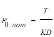
Torque is relatively easy to measure with a torque wrench, so it is the most frequently used indicator of bolt tension. Unfortunately, a torque wrench does not measure bolt tension accurately, mainly because it does not take friction into account. The friction depends on bolt, nut, and washer material, surface smoothness, degree of lubrication, and the number of times a bolt has been installed. Fastener manufacturers often provide information for determining torque requirements for tightening various bolts. If this information is not available, the maximum and minimum expected preloads for bolt diameter ≤ ¾” in the joint can be estimated using the equations below [3].
![]()
![]()
where
P0,nom = nominal bolt preload
Po,max = maximum expected bolt preload (lb)
Po,min = minimum expected bolt preload (lb)
T = applied torque (in-lb)
K = typical nut factor, 0.11 to 0.15 for lubricated fasteners and 0.2 for unlubricated fasteners,
D = nominal fastener (shank) diameter (in)
u = preload uncertainty factor, typically 25%
Prelax = axial bolt preload loss (lb), typically 5% of Po,min
As an alternative to the typical nut factor method of determining preload, the torque-preload relationships can be determined experimentally. Here, the torque-preload relationships are determined by direct measurements taken from instrumented joint specimens. Statistical data is recorded for the torque required to achieve a desired bolt force. Preload loss can also be measured over time.
Bolt elongation is directly proportional to axial stress when the applied stress is within the elastic range of the material. If both ends of a bolt are accessible, a micrometer measurement of bolt length made before and after the application of tension will ensure the required axial stress is applied.
The ultrasonic method of measuring elongation uses a sound pulse, generated at one end of a bolt that travels the length of a bolt, bounces off the far end, and returns to the sound generator in a measured period of time. The time required for the sound pulse to return depends on the length of the bolt and the speed of sound in the bolt material. The speed of sound in the bolt depends on the material, the temperature, and the stress level. For short bolts (L/D of less than 4:1) significant uncertainty may be dominated by the uncertainty in grip and thread lengths that determine the effective length of the fastener.
The turn-of-nut method applies preload by turning a nut through an angle that corresponds to a given elongation. The method of calculating the nut-turn angle requires elongation of the bolt without a corresponding compression of the joint material. The turn-of-nut method, therefore, is not valid if there is a significant deformation of the nut and joint material relative to that of the bolt. The nut-turn angle would then have to be determined empirically using a simulated joint and a tension-measuring device.
Preload relaxation may result over a period of minutes to hours after the first application of the preload due to:
Retightening after several minutes to several days may be required. As a general rule, an allowance for loss of preload of about 5 per cent [3] may be made when designing a joint.
Over an extended period of time, preload may be reduced or completely lost due to:
The use of locking methods that prevent relative motion of the joint may reduce the problem of preload relaxation due to vibration and temperature cycling. Creep is generally an effect of softer material or bolt material at elevated temperature. Differences in thermal expansion of the bolts and flange materials that might cause preload to increase or decrease must be taken into consideration.
Application specific testing refers to test conditions that closely resemble the actual configuration. The preload uncertainties defined above can be used for small fasteners. Application specific testing is required for large fasteners. In general, a fastener is considered large if it has a diameter > 3/4”. An application specific test must include the following items:
Care must be taken to maintain the calibration of torque and load indicators. Preload test shall include both the through-bolt joint and tapped-bolt joint. The preload loss shall evaluate the short-term preload relaxation and creep of the joint materials, but not the effects of vibration and the thermal cycling. Additional joint stiffness may be determined either by analysis or an application specific test. Fatigue S-N data may be obtained from the manufacture.
The torque-preload relationships and the preload loss are determined by direct measurements taken from instrumented joint specimens. A valid application specific test must include an adequate sample and an acceptable statistical analysis.
Re-torquing of preloaded bolts using torque measurements as the means of determining the preload often results in unexpected preload values. If torque measurements are used to determine the preload in bolts which have undergone one or more installation cycles, they require
An installation cycle is defined as a procedure which produces a positive torque (increases preload) and then subsequently a negative torque (decreases preload) on a bolt. A preloaded bolt is in its first installation cycle until it is subject to a negative torque for the first time. Therefore, a bolt that has lost preload due to relaxation but as not been subject to a negative torque may be re-torqued and still considered to be in its first installation cycle.
Consider a joint that consists of a number of elements stacked on top of one another. The grip length Lg is measured from the bottom of the bolt or nut (if used). If a tapped hole is used, the grip length is measured to the middle of the engagement length. The stiffness of an individual element ki is equal to

![]()
Where
Ei = the elastic modulus of the element
Ai = the area of the element in the plane normal to the bolt
Li = the thickness of the element
Where there is a change in area, e.g. through a flange, it may be assumed that the effective area grows along a 45º angle. Alternatively, the equivalent cylinder method [6] may be used to calculate the effective area. These methods are approximate. Finite element analysis and testing are better options for evaluating the joint stiffness.
The stiffness of the bolt results from the stiffness of the bolt shank and the stiffness of the bolt thread. A bolted joint can include a number of separate parts and the individual part stiffness can be calculated approximately. The joint stiffness kj is related to the individual stiffness values as shown below.

where
n = number of elements in the joint
kj = joint stiffness (lb/in)
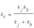
The total stiffness kt is
The bolt preload may change due to a number of effects including
If the bolt and flange materials have different coefficients of thermal expansion and the joint is subjected to a temperature change DT, it introduces a tension or relaxation in the bolt. The thermal strain in an element eth,i is
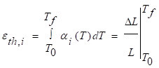
where
ai = the coefficient of thermal expansion for the ith element.
The change in preload DP is
![]() .
.
A change in elasticity with temperature can result in a change in preload. Let kt,0 represent the total joint (bolt plus joint) stiffness at the installation temperature and kt,1 represent the total joint stiffness at operating temperature. If P0 is the installation preload, the change in preload DP is
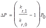 .
.
Creep is generally characteristic of soft materials or materials at elevated high-temperature. If the creep deformation dc (a negative number) is known, the change in preload DP is
![]() .
.
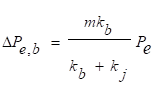
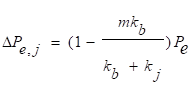
When an external load Pe is applied which tends to separate the joint, part of this load will cause the further extension of the bolt, resulting in an increase in the bolt load DPe,b. Part of the load will result in an increase of the joint thickness, resulting in a decrease in the load on the joint DPe,j.
![]() .
.
For common joint designs the load is carried somewhere near the midplane of each flange. The loading plane factor m is defined as the ratio of the distance between loading planes divided by the total thickness of the joint.
The resulting preload changes on the bolt and joint are
Fatigue life of a bolt is determined by the magnitudes of mean and alternating stress imposed on the bolt by external cyclic loads. If there is no bolt preload in loaded bolt joint, the bolt load is equal to the joint load. However, if preload is applied to the bolt, the joint is compressed and bolt load changes more slowly than the joint load as shown in Section 2.3.7.4 because some of the load is absorbed as a reduction of compression in the joint. This condition results in a considerable reduction in cyclic bolt-load variation and thereby increases the fatigue life of the fastener.
Fatigue life usually presented in the form of S-N diagrams, where S stands for stress amplitude and N for number of cycle of applied load. The stress concentration points at the thread roots and the head-to-body fillets are the major factor, which affect fatigue life.
Joints required to resist shear are designed as either friction-type or bearing-type connections. When shear connections subjected to stress reversal, severe stress fluctuation, or where slippage would be undesirable, AISC [4] recommends using a friction-type connection.
In shear-loaded joints with members that slide, the joint members transmit shear loads to the bolts in the joint and the preload must be sufficient to hold the joint members in contact and without additional sliding during the stress cycle. Therefore, the bolts are subjected to both tensile and shear loading simultaneously.
In joints that do not slide, shear loads are transmitted within the joint by frictional forces that mainly result from the preload. Therefore, preload must be great enough for the resulting friction forces to be greater than the applied shear force.
Shear loads are also produced due to preload torque. The shear stress induced in the bolt during application of the preload must also be considered in the bolted joint design. Joints with combined axial and shear loads must be analyzed to ensure that the bolts will not fail in tension, shear or combined tension and shear.
Bolt bending may result from double shear, misalignment during assembly, use of long spacers, prying action, or from flanges that are several orders of magnitude stiffer than the bolt. In the latter case the flange tends to rotate as a rigid body, forcing the head of the bolt to rotate which applies moment loading to the bolt.
In general, for preloaded joints to work effectively they must meet the following criteria:
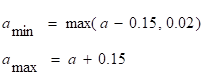
The maximum and minimum preloads must be determined taking into account the following considerations:
The allowable stress criteria are defined in the NCSX Structural and Cryogenic Design Criteria [5]. The shear loads and tensile loads due to bolt preload and external loads shall be calculated from theoretical or empirical equations and the finite element analysis.
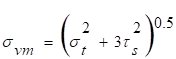
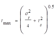
where st is the axial applied tensile stress and ts is the shear stress caused by the torsion load application.
![]()
where Rt is the ratio of maximum axial load to axial load allowable and Rs is the ratio of shear load to shear load allowable.
![]()
where Rb is the ratio of maximum bending load to bending load allowable.
For allowable coefficients of friction above 0.45, use
The preload stress level and the cyclic stress variation shall provide acceptable fatigue life.
[1] Oberg, E., Jones. F., Horton, H., and Ryffel, H., Machinery’s Handbook, 27thEdition, Industrial Press Inc., New York, 2004
[2] Criteria for Preloaded Bolts, NSTS–08307, Rev. A, NASA, 1998
[3] Chambers, J., Preloaded Joint Analysis Methodology for Space Flight Systems, NASA Technical Memorandum 106943, 1995
[4] Manual of Steel Construction, AISC, Seventh Edition, 1970
[5] NCSX Structural Design Criteria, NCSX-CRIT-CRYO-00, NCSX Specification, Nov. 29 2004
[6] Bickford, John H., An Introduction to the Design and Behavior of Bolted Joints, 3rd Edition, Marcel Dekker, Inc., New York, 1995
![]()
![]()
![]()
![]()
![]()
![]()
![]()
![]()
![]()
From Wikipedia, the free encyclopedia
The Unified Thread Standard (UTS) defines a standard thread form and series – along with allowances, tolerances, and designations – for screw threads commonly used in the United States and Canada. It has the same 60° profile as the ISO metric screw thread used in the rest of the world, but the characteristic dimensions of each UTS thread (outer diameter and pitch) were chosen as an inch fraction rather than a round millimeter value. The UTS is currently controlled by ASME/ANSI in the United States.
The standard was originally adopted by the Screw Thread Standardization Committees of Canada, the United Kingdom, and the United States on Nov 18, 1949 in Washington, D.C., and applied to screw threads used in the above countries with the hope they would be adopted universally. The standard was not widely taken up in the UK, who continued to use their own BA (British Association) standard and then migrated to ISO metric screw threads. The original UTS standard may be found in ASA (now ANSI) publication, Vol. 1, 1949.
UTS consists of Unified Coarse (UNC), Unified Fine (UNF), Unified Extra Fine (UNEF) and Unified Special (UNS).
The International Organization for Standardization's ISO metric screw thread preferred series, based on round millimeter dimensions, is the standard that has been adopted world-wide and has displaced all former standards, including UTS. In the USA, where UTS is still prevalent, over 40% of products contain ISO metric screw threads. Of the above mentioned countries, the UK has completely abandoned its commitment to UTS in favour of the ISO metric threads, and Canada is in between.
UTS thread form and pitch technical specifications are currently controlled by ASME/ANSI industry standards in the United States:
ASME/ANSI B1.1 - 2003 Unified Inch Screw Threads, UN & UNR Thread Form
ASME/ANSI B1.10M - 2004 Unified Miniature Screw Threads
ASME/ANSI B1.15 - 1995 Unified Inch Screw Threads, UNJ Thread Form
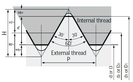
P = 1 / TeethPerInch
H = 0.866025 * P
H1 = 0.541266 * P
d1 = d + 1.082532 * P
d2 = d + 0.433013 * P
D = d
D1 = d1
D2 = d2
A screw thread gauging system comprises a list of screw thread characteristics that must be inspected to establish the dimensional acceptability of the screw threads on a threaded product and the gauge(s) which shall be used when inspecting those characteristics.
Currently this gauging UTS is controlled by:
ASME/ANSI B1.2-1983 Gauges And Gauging For Unified Inch Screw Threads
ASME/ANSI B1.3M-1992 Screw Thread Gauging Systems Dimensional Acceptability Inch Metric Screw Threads
These Standards provide essential specifications and dimensions for the gauges used on Unified inch screw threads (UN, UNR, UNJ thread form) on externally and internally threaded products. It also covers the specifications and dimensions for the thread gauges and measuring equipment. The basic purpose and use of each gauge are also described. It also establishes the criteria for screw thread acceptance when a gauging system is used.
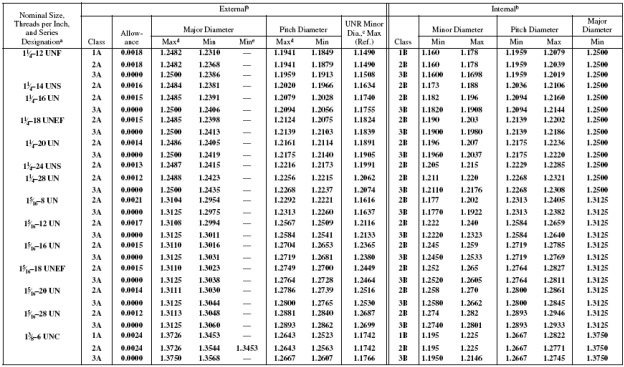
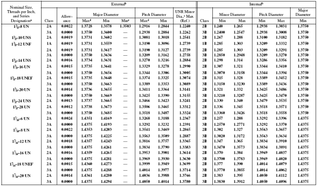
A classification system exists for ease of manufacture and interchangeability of fabricated threaded items. Most (but certainly not all) threaded items are made to a classification standard called the Unified Screw Thread Standard Series. This system is analogous to the fits used with assembled parts.
Classes 1A, 2A, 3A apply to external threads; Classes 1B, 2B, 3B apply to internal threads.
Class 1 threads are loosely fitting threads intended for ease of assembly or use in a dirty environment.
Class 2 threads are the most common. They are designed to maximize strength considering typical machine shop capability and machine practice.
Class 3 threads are used for closer tolerances.
Thread class refers to the acceptable range of pitch diameter for any given thread. The pitch diameter is shown as d2 in the figure above. There are several methods that are used to measure the pitch diameter. The most common method used in production is by way of a Go-NoGo gauge.
A table of pitch diameters and thread classes can be found here.
ISO metric screw thread
British Standard Whitworth
British Association screw threads
Wrench Most common tool used to loosen/tighten screws.
National pipe thread
Unified Coarse standard and drill sizes
Unified Fine standard and drill sizes
International Thread Standards
Spanner Jaw Sizes Additional information and spanner jaw size table.
Retrieved from "http://en.wikipedia.org/wiki/Unified_Thread_Standard"
Retrieved from http://en.wikipedia.org/wiki/Unified_Thread_Standard
Machinery’s Handbook 27th Edition
Source: http://ncsx.pppl.gov/NCSX_Engineering/Design_Criteria/BoltedJoint/NCSX-CRIT-BOLT-00-Signed.doc
Web site to visit: http://ncsx.pppl.gov
Author of the text: indicated on the source document of the above text
If you are the author of the text above and you not agree to share your knowledge for teaching, research, scholarship (for fair use as indicated in the United States copyrigh low) please send us an e-mail and we will remove your text quickly. Fair use is a limitation and exception to the exclusive right granted by copyright law to the author of a creative work. In United States copyright law, fair use is a doctrine that permits limited use of copyrighted material without acquiring permission from the rights holders. Examples of fair use include commentary, search engines, criticism, news reporting, research, teaching, library archiving and scholarship. It provides for the legal, unlicensed citation or incorporation of copyrighted material in another author's work under a four-factor balancing test. (source: http://en.wikipedia.org/wiki/Fair_use)
The information of medicine and health contained in the site are of a general nature and purpose which is purely informative and for this reason may not replace in any case, the council of a doctor or a qualified entity legally to the profession.
The texts are the property of their respective authors and we thank them for giving us the opportunity to share for free to students, teachers and users of the Web their texts will used only for illustrative educational and scientific purposes only.
All the information in our site are given for nonprofit educational purposes