The construction of CNC lathes can vary from a simple two axis machine resembling a conventional engine lathe to multi-axis multi-spindle machines often found in the manufacturing industry. Regardless of the physical shape or configuration of each machine the fundamentals of programming remain the same.
|
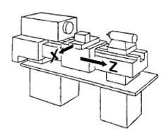
On a simple two axis lathe as shown in figure 1.23 the following rules apply: |
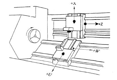
Figure 1.24 Two sliding turning centre
Not all CNC lathes are simple two axis machines. The lathe shown in Figure 1.24 has two tool slides each of which are controlled by the part program. In this example:
X axis = Diameter
U axis = Diameter
Z axis = Length
W axis= Length
Answers are at the end of CNC Machining text
This section covers the basic operation of CNC machines with regard to axes movement, stored stroke limits and buffer storage, work handling methods and the role of CNC in flexible manufacturing systems.
At the end of this section, you will be able to:
Once the Machine Control Unit has decoded the part program it can now send the signals required to drive and position the table and tool slides as required by the program. This chain of event normally involves three specific sub units.
The figure below shows the general flow path of signals which drive, position and control all aspects of slide motion.
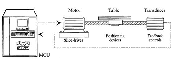
Figure 2.1 Machine motion drives and controls
In general, the multi-change gear boxes with fixed ratios driven by constant speed electric motors, as commonly used on conventional machine tools, are not always entirely suitable for NC machines. Variable speed drives enable cutting speeds and feeds to be maintained at optimum values, thus utilising a machines cutting capacity to the full. The extra cost of providing variable speed drives and the somewhat lower efficiency of the units (disadvantages in relation to conventional machines) are less significant on NC machine tools because the higher cost and depreciation rates of NC machines make it essential to fully exploit their potential.
On NC machine tools, speed changes are carried out in response to instructions written into the tape input data according to the machining program. Selection of the most suitable ratio is readily carried out ifvariab1e speed systems are used in the transmission. Some of the recognised methods of obtaining speed ratios are considered in the following paragraphs.
For reasons mentioned above, the conventional fixed ratio gearbox is used less often in NC applications, but when the system is used, the gears providing the various ratios are usually in constant mesh and remotely controlled electro-magnetic or hydraulic clutches are employed to engage the selected ratio. Variable speed drives based on mechanical principles have limitations in respect of the rate at which a change can be carried out, and of the relatively high forces which are needed to operate the change.
Drives in which speed variation is obtained entirely by electrical means are of two main types, ie. systems utilising either an AC or a DC final drive motor. The AC motor achieves speed variation by changing the frequency of the supply through a frequency controller. The DC motor speed variation is obtained by altering the DC supply voltage, which in tum has been converted from normal AC supply. Both the AC and DC motors offer similar speed/power performance, with the AC motor being smaller and lighter and therefore giving superior acceleration and deceleration. Because the AC motor is an induction motor, it does not have brushes to wear and to replace as does the DC motor, but the DC motor is less expensive to produce and fit to the machines.
Hydrostatic hydraulic drives are being used increasingly for NC applications. The usual system spindle drives is based on a constant speed electric motor driving and hydraulic pump which then supplies hydraulic oil under pressure to drive an hydraulic motor. The pumps and motors may be of either the fixed or the variable displacement type, and the choice will often depend on the characteristics required from the output, ie. high efficiency, rapid response, constant torque, constant power, wide speed range, etc.
Advantages of hydraulic systems, especially those incorporating both variable delivery pumps and variable displacement motors, are:
Disadvantages
Many of the foregoing comments relating to spindle drives will also apply to drives operating feed mechanisms, ego drives to tables and slides, whereas rotary drives are required for spindles, linear motion is usually required for feed mechanisms. The choice of mechanism is largely confined to:
Each of these mechanisms have their place, and all can be readily controlled for NC purposes. The choice is usually influenced by two factors, the length of stroke and the mass to be displaced.
Hydraulic rams are suitable for relatively short strokes and are particularly attractive for low and medium power ranges. Hydraulic actuators are economic and provide a smooth, still transmission in the smaller range, but as size increases, compliance becomes something of a problem. The column of oil in a cylinder is subjected to slight compression and acts as a liquid spring. In addition, slight elastic deflection of mechanical elements, ego cylinder walls, may occur. When such considerations become noticeable, a change is frequently made to a leadscrew drive.
Rack and pinion drives are particularly suitable for moving the slides of very large machines mainly because the range of stroke is not limited as is the case for machines relying on a leadscrew. Very long leadscrews need to be well supported and are generally of large diameter to minimise linear and torsional deflection over their length. Machine slides operates by rack and pinion have the advantage of high rigidity regardless of stroke length although the positional accuracy of rack and pinion systems is not as high as other methods.
Screw thread drives used on conventional machine tools, usually employ trapezoidal threads, ego Acme. These thread have several disadvantages. They are very inefficient (often less than 25% efficiency is obtained form Acme thread), due to high frictional resistance between the flanks of the screw and nut -and with the increased diameter of leadscrews used on NC machines this friction increases the torque requirements.
The friction gives rise to local heat, and inaccuracy results from this cause. Backlash of the magnitude met with in normal screw drives is quite unacceptable for many NC applications; it can be removed by using a backlash eliminator, but this device introduces further frictional resistance and accentuates the problems referred to above.
The use of recirculating ball leadscrew and nut, ensures which the connection between the screw and nut is achieved by an endless stream of recirculating steel balls.
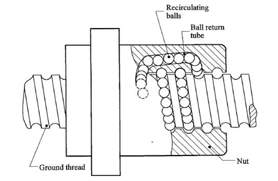
Figure 2.2 Recirculating ball leadscrew
The efficiency of the recirculating ball screw is very high, often 90%, and even when subject to pre-loading to eliminate backlash, the frictional resistance is still not objectionable and the efficiency remains remarkably high.
In the open loop system, shown below, the tape is fed into a tape reader which decodes the information punched on the tape and stores it briefly until the machine is ready to use it. The tape reader then coverts the information into electrical pulses or signals. These signals are sent to the control unit, which energises the servo control units. The servo control units direct the servomotors to perform certain functions according to the information supplied. The amount each servomotor will move depends upon the number of electrical pulses it receives from the servo control unit.
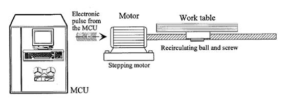
Figure 2.3 Open loop control
Precision leadscrews, usually having 10 threads per inch (tpi), are used on NC machines. If the servomotor connected to the leadscrew receives 1000 electrical pulses, the machine slide will move 1 in. (25.4 mm). Therefore, one pulse will cause the machine slide to move 0.001 in. (0.0254 mm). The open loop system is fairly simple, however, since there is no means of checking whether the servomotor has performed its function correctly, that is, no means of feedback, this system is not generally used where an accuracy greater than 0.001 in. (0.025 mm) is required.
The closed loop system is similar to the open loop system with the exception that a feedback unit is introduced into the electrical circuit. This feedback unit, often called a transducer, converts the movement by the servomotor to an electrical signal. The control compares the signal received from the transducer to the signal that was sent to the servomotor and will instruct the servomotor to make whatever adjustments are necessary until both the signal sent from the control unit and the one received from the servo unit are equal. 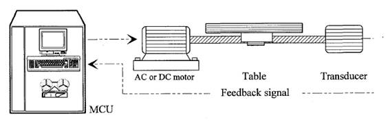
Figure 2.4 Closed loop feedback control
Closed loop NC systems are very accurate because the command signal is recorded, and there is an automatic compensation error. If the machine slide is forced out of position due to cutting forces, the feedback unit indicates this movement and the machine control unit (MCU) automatically makes the necessary adjustments to bring the machine slide back to position.
‘A transducer is a device that converts one form of energy into another form of energy in such a way that the output is a known function of the input’.
Transducers used on most modem day NC/CNC machines are either analog or digital systems.
Analog transducers, such as potentiometers and synchros, produce an electrical voltage which varies as the input shaft is turned or rotated. This voltage is in proportion to the rotation of the input shaft which can be converted into very accurate machine table positions.
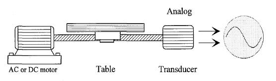
Figure 2.5 Analog transducer system
Digital feedback units, attached to the leadscrew of a machine tool change the rotary motion of the machine screws to individual or discrete electrical pulses. This series of pulses can be counted to indicate exactly how much the leadscrew shaft has turned, which indicates the amount the machine table has moved.
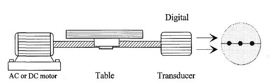
Figure 2.6 Digital transducer system
Transducers used in closed loop system may be divided into two broad groups.
Resolvers generate their signal directly by having windings at 90 0 on the rotor and two windings at 90 0 in the stator. An AC voltage is applied to a stator winding, and as a rotor winding passes it a voltage is generated on that winding. This voltage is treated in such a way as to provide an electrical pulse that can be used for positional information without the necessity of photo electric devices or brushes.
Rotary transducers are usually fitted at the opposite end of the ballscrew to the motor as shown in the preceding sketches, or they are fitted to the end of the motor. This means they actually determine the motion of the ballscrew or the motor and not necessarily the machine slideway itself.
Tachometers are used to sense velocity and are small DC generators coupled to the leadscrew or motor shaft and supply a voltage that increases in direct proportion to its speed of rotation. This voltage represents the actual speed and can be used in comparison to the voltage supplied for the desired speed as a method of reducing the velocity error to a minimum.
There are also linear devices, the most well known being the inductosyn. These transducers work by having two grating combs mounted closely over one another, one fixed, one moving with the slide. The gratings are pitched differently, giving an effect like an electronic version of a vernier scale. Signals are usually generated electrically, but can also be generated by photo electric devices.
Linear transducers are similar in construction to the digital readout scales fitted to manual machines. These linear scales are fitted to the actual slideway so they determine the motion of the slideway.
Limit switches are used to control motion at the extreme position of each slide and may take the form of physical (hard wired) switches, or a stored (soft wired) position within the control. Depending on the machine, there may be two or three limit switches per slide with the outermost switch (usually hard wired) being the emergency limit position. Once the machine is in normal operation this switch is not activated. If, due to some error this switch is activated, an alarm condition will exist with power isolated from the servo motors and only resetable through the emergency over travel release sequence. This will prevent in many cases any mechanical damage to the axis drive assembly.
Just inside the emergency limit position switch is the stroke end limit position (usually soft wired). If this position is exceeded during manual (JOG) operation an alarm will exist and can usually be cleared simply by moving the slide away in the opposite direction.
On some machines (particularly lathes) there can be a third limit position -this is a soft wired variable limit and the position will be set as desired to suit the size of the workpiece. Turret indexing is executed at this position. The variable limit can be set to the same position as the stroke end limit position.
Variable limits can also be set on some machines to create an area that is forbidden to the tool. This 'forbidden area' or 'barrier' is activated only when an appropriate code is programmed, or entered into the MCU from the keyboard.
The function of this feature is to reduce the possibility of tool collisions. As there are variations between machines, it will be worthwhile conferring with your teacher to find out how the machine you are operating is configured.
Primarily, buffer storage s used in N.C. and CNC controls to permit smooth continuous motion from block to block.
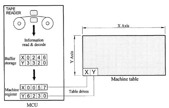
Figure 2.7
Most modem NC and CNC controls are equipped with buffer storage. As shown above, this feature allows the control to accept information into a buffer register while an operation is being performed from the active machine registers. When that operation is completed, the information is transferred from buffer storage to the machine actuation registers. This transfer of information is instantaneous, thereby reducing the time between tape reading and machine performance.
Buffer storage reduces the amount of dwell time between machine operations because the next block of tape is read and stored while the machine is executing the previous block. Part finish is also better because the cutter does not come to a halt to process the next block of information in the middle of curves, angles, or other part configurations.
Buffer storage may differ from one control to another, some CNC controls being capable of decoding and buffering 200 blocks of program information ahead of machine motion. In this situation program errors can be detected and corrected during program trialing without necessarily having to restart the program from the beginning.
Raw materials and components must be handled at various stages of manufacture, also tooling and fixturing will require handling at some time.
The more automatic any of these processes can be made, the more efficient a system will become.
The trade-off against the shortest time it takes to convert raw materials into finished assemblies will be the cost of building or installing automated handling equipment.
Obviously, mass production lends itself to automation at all levels, but efficiencies can be improved in jobbing shops by reducing manual handling as much as possible.
Work handling methods that can be used singly or jointly commonly in use are:
Most modem CNC Machining Centres have some form of automated tool change system which can select and load tools as they are required. Both the process of selection and loading are controlled by the Machine Control Unit which responds to program instructions by activating the tool change routine.
Turret type tool changers are often 6, 8 or 12 station turrets designed to hold stub arbor or collet mounted milling cutters.
Source: http://lrr.cli.det.nsw.edu.au/LRRDownloads/12571/1/12571.doc
Web site to visit: http://lrr.cli.det.nsw.edu.au
Author of the text: indicated on the source document of the above text
If you are the author of the text above and you not agree to share your knowledge for teaching, research, scholarship (for fair use as indicated in the United States copyrigh low) please send us an e-mail and we will remove your text quickly. Fair use is a limitation and exception to the exclusive right granted by copyright law to the author of a creative work. In United States copyright law, fair use is a doctrine that permits limited use of copyrighted material without acquiring permission from the rights holders. Examples of fair use include commentary, search engines, criticism, news reporting, research, teaching, library archiving and scholarship. It provides for the legal, unlicensed citation or incorporation of copyrighted material in another author's work under a four-factor balancing test. (source: http://en.wikipedia.org/wiki/Fair_use)
The information of medicine and health contained in the site are of a general nature and purpose which is purely informative and for this reason may not replace in any case, the council of a doctor or a qualified entity legally to the profession.
The texts are the property of their respective authors and we thank them for giving us the opportunity to share for free to students, teachers and users of the Web their texts will used only for illustrative educational and scientific purposes only.
All the information in our site are given for nonprofit educational purposes