
CAM
Cams are used to convert rotary motion into reciprocating motion. The cam mechanism consists of two elements, the cam and the follower. Normally cams are drivers and the followers are driven. Cams are used in internal combustion engines, where they are used to operate the inlet and exhaust valves.
Based on modes of Input / output motion:
Fig 1.1 Classification of cam mechanisms
Fig 1.2 Translating cam – Translating follower
1.2.1According to the shape of follower
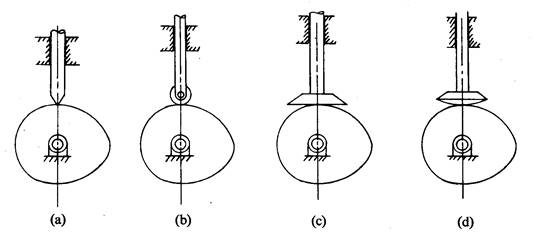

Fig 1.3 Types of followers
1.2.2 According to the path of motion of follower
a) Radial follower:
When the motion of the follower is along an axis passing through the centre of the cam, it is known as radial followers. (Fig 1.3 a,b,c,d) are examples of this type.
b) Off – set follower:
When the motion of the follower is along an axis away from the axis of the cam centre, it is called off-set follower. (Fig 1.4 a,b,c,d) are examples of this type.
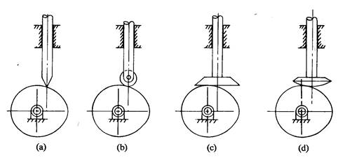

Fig 1.4 Different types of offset followers
In radial cams, the follower reciprocates or oscillates in a direction perpendicular to the cam axis. The cams shown in fig 1.1, fig 1.2, fig 1.3 and fig 1.4 are examples of this type.
In cylindrical cams, the follower reciprocates or oscillates in a direction parallel to the cams axis. Fig 1.5a is an example.
It is also similar to cylindrical cams, but the follower makes contact at periphery of the cam as shown in fig 1.5b.
Fig 1.5 Cylindrical cam and End cam
2. Cam Nomenclature:
Fig 1.6 Cam nomenclature
As the cam rotates the follower moves upward and downward. The upward movement of follower is called rise and the downward movement is called fall. When the follower is not moving upward and downward even when the cam rotates, it is called dwell.
In general there are four types of motion of follower.
The follower moves with constant velocity. It is applicable for rise and fall of the follower.
Displacement diagram:
It is the plot of linear displacement (s) of follower V/S angular displacement (θ) of the cam for one full rotation of the cam.
Velocity diagram:
It is the plot of linear velocity of follower V/S angular displacement (θ) of the cam for one full rotation of the cam.
Acceleration diagram:
It is the plot of linear acceleration of follower V/S angular displacement (θ) of the cam for one full rotation of the cam.
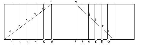
Fig 1.6 Displacement diagram for uniform motion
Since the follower moves with uniform velocity during its rise and fall, the slope of the displacement curve must be constant as shown in fig 1.6
The displacement diagram, velocity diagram and acceleration diagram for SHM is shown in fig 1.7
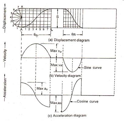
Fig 1.7 Displacement, Velocity and Acceleration diagrams of SHM
Since the follower moves with a simple harmonic motion, therefore velocity diagram consists of a sine curve and the acceleration diagram consists of a cosine curve.
The displacement diagram, velocity diagram and acceleration diagram for Uniform acceleration and retardation is shown in fig 1.8
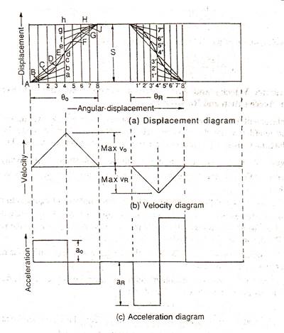
Fig 1.8 Displacement, Velocity and Acceleration diagrams of Uniform acceleration and retardation motion
Since the acceleration and retardation are uniform, therefore the velocity varies directly with time.
The displacement diagram, velocity diagram and acceleration diagram for Cycloidal motion is shown in fig 1.9
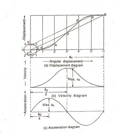
Fig 1.9 Displacement, Velocity and Acceleration diagram of Cycloidal motion
The sample cam profile as shown in fig 1.10
Fig 1.10 CAM Profile
References:
Source: http://www.srmuniv.ac.in/downloads/combustion.doc
Web site to visit: http://www.srmuniv.ac.in
Author of the text: indicated on the source document of the above text
Theory Machines 4
A Cam is a mechanical element used to drive another element, a follower, through a specified motion by direct contact. Follower motions having almost any desired characteristics are not difficult to design. By desired characteristics are typically meant the following: displacement – the height or distance through which the follower is moved for one revolution of the cam; velocity – the speed with which the cam moves the follower; acceleration – the rate of change of velocity of the follower (remember force – mass x acceleration ); jerk – the rate of change of acceleration. The problem in cam design is how to determine a cam contour that will ultimately deliver a specified motion with acceptable velocity, acceleration and jerk.
CLASSIFICATION OF CAMS AND FOLLOWERS:
Most common type of cam. Follower may not be radial in some applications, ie, the centre of the roller, the centre of cam rotation and direction of follower travel may not coincide.
Diagram 31

Translation Cam (Wedge Cam)
Not very commonly used. The cam moves over and back, reciprocating motion, which drives the follower vertically. Cam reciprocating motion may be due to a pneumatic or hydraulic cyliner, rack and pinion, or some other linear output device.
Diagram 32

Again not a very common device but may be used where it is required to have the axis of rotation of the of the cam parallel to the direction of follower motion
Diagram 33

Axis of rotation of the cam and follower direction of motion are parallel but not collinear. The cam is essentially a cylinder cut at an angle to the axis of rotation. The follower rides on the perimeter of the cylinder as the cam rotates.
Diagram 34

There are a range of follower types which are used but all effectively perform the same function – they follow the cam profile as designed. What is important is that they must remain in contact with the cam surface at all times. Failure to do so will lead to non-predictable motion, ie. something other than the cam profile may determine the follower displacement, vel. accel and jerk at a given instant. Impact, noise, excessive wear or damage to cam and follower surfaces may result from the follower losing contact with the cam surface. Gravity, springs and mechanical constraint are used to ensure that the follower is pressed tightly against the cam surface as it rotates.
Diagram 35

Follower stem lines up with the cam axis of rotation
Diagram 36
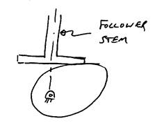
Diagram 37

Diagram 38
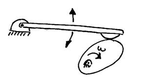
The input motion θ (t) is derived from the angular velocity of the shaft, ω. The output displacement of the follower Y(t) consists of rises, dwells and falls. What is typically required is to design a cam to provide an output motion Y ( t ) for a given angular motion input. The diagram below shows a typical displacement diagram for a disc cam with one rise, one fall and two dwells occurring within a cam rotation of 360 degrees. A cam may have multiple rises and falls, no dwells, or whatever configuration is necessary for the desired follower motion.
Diagram 39

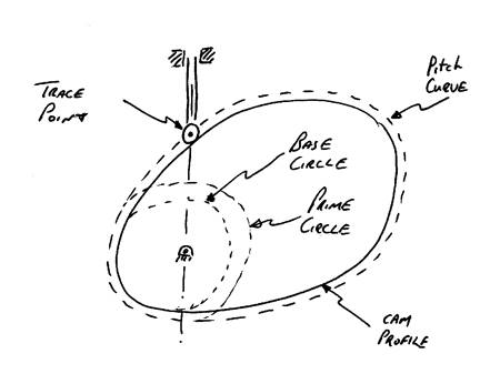
CAM VOCABULARY AND DEFINITIONS
Pitch Curves: Locus generated by the trace point – for a knife-edge follower the pitch curve is the cam surface. For a roller follower the trace point is the centre of the roller therefore the pitch curve is outside the cam surface
Prime Circle: This is the smallest circle tangential to the pitch curve and with its centre at the cam centre of rotation.
Base Circle: This is the smallest circle tangential to the cam surface and with its centre at the cam centre of rotation.
Dwell Periods: Where no follower displacement occurs even though the cam is rotating.
Diagram 40
Dwell periods are typically decided by the application, ie. in a motor car engine the valve must remain closed or open for a fixed period. Design a dwell is not difficult. However linking a dwell with a rise or return poses a lot of problems as the follower must go from a velocity and acceleration of zero into a motion with specific velocity and acceleration – the transition is where the difficulty lies/
Rise and return have many possible follower motions - uniform motion, parabolic, harmonic, cycloidal, etc. so a choice available to the designer/
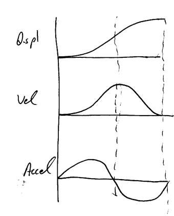
This is where the follower moves at a constant velocity. The rise or fall on a displacement diagram is thus plotted as a straight line. Problems arise where the uniform motion meets a dwell. As can be seen below this gives rise to discontinuities in the velocity, acceleration and jerk curves. (Jerk is the rate of change of acceleration and is very important in determining the smoothness of the displacement curve)
Diagram 41

Modified uniform motion is where uniform or constant velocity motion is linked to a dwell using a parabolic curve. The displacement diagram below shows a dwell linked to a constant velocity using a parabolic rise θ1 and further on the constant velocity section θ2 is linked back to the dwell at the top of the rise using another parabolic section θ3.
Diagram 42

The displacement of a body moving from rest with a constant acceleration is
S = ½ At2 S = displacement.
A = acceleration.
t = time.
This is the equation for a parabola (x2 = ky where k = constant) so that motion involving constant acceleration is often called parabolic motion. The following shows how a parabolic motion may be used to link a dwell and a constant velocity section in a displacement diagram
For a curve where displacement, h, and θ are the coordinates, h = ½ B θ2 and θ = ωt where ω is constant, B = A/ω. = Accel/Ang Vel.
Diagram 43

O-M Parabolic rise h occurring in angle θ1
M-N Constant Velocity Rise(Vel = V) with rise h occuring in angle θ2
h = ½ B.θ12 which implies B = 2h/ θ12
V = B.θ1 = 2h/ θ1 Eqn. 1
For constant velocity rise to M, assuming no parabolic section.
h = V.θ2 or V = h/ θ2 Eqn. 2
θ1 = 2. θ2 From equations 1 and 2
So that the point of inflection of the parabolic and constant velocity curves is twice the distance of the point of intersection of the constant velocity portion alone.
Diagram 44

As can be seen above the solution is not ideal as, while velocity and acceleration remain within finite limits, jerk reaches infinite values at the start and end of each parabolic section.
In pure harmonic motion the 1st, 2nd and 3rd derivatives of displacement all remain finite. As can be seen for the circular cam, radius R and rotating about a centre a distance b from the true centre, and flat face follower shown below a set of equations to describe follower motion in terms of cam angle of rot can be derived.
Diagram 45

Y = R + b cos θ Displacement of follower
dY/dt = - b sin θ dθ/dt where dθ/dt = ω
dY/dt = - b ω sin θ dθ/dt = Velocity
d2Y/dt2 = -b ω2 cos θ = Acceleration
d3Y/dt3 = -b ω3 sin θ = Jerk
Minimum follower face width = 2b
As can be seen below the motion of the follower is harmonic and there are no discontinuities. A circular cam (eccentre) imparts SHM to a radial flat faced follower.
Diagram 46

When creating a displacement diagram for SHM the method shown below may be used. A semicircle of diameter equal to the required rise is split into an equal number of segments as the cam angle line or horizontal axis of the diagram. Simply drawing across to find the intersection points creates the curve.
Diagram 47

Suppose SHM is asked to combine with a dwell the following are the resultant diagrams.
Diagram 48

CYCLOIDAL MOTION:
A cycloid is the locus of a point on a circle as the circle rolls on a straight line.
Diagram 49

To create a cycloidal motion in cam design involves superimposing cycloidal motion on constant velocity motion. See the graphical method shown below for creating a cycloidal curve.
Diagram 50

In designing a cam profile with cycloidal motion the total displacement, h, needs to be equal to the circumference of the circle creating the cycloid. A circle of radius r = h/2Π makes one revolution in going from zero displacement to maximum displacement h. X traces a cycloid and the graph of X as it moves vertically generates the displacement diagram.
Diagram 51

At point X the displacement for the centre of the circle describing the cycloid is rф.
The actual displacement of point X is given by
X = rф – rsinф = r (ф – sinф)
As regards cam rotation the rise s occurs inside an angle β and total rise h occurs inside an angle α
Therefore ф = 2Π (β/α) = 2Π x ( fraction of total rotation for rise h)
Also r = h/2Π
Combining the above gives the following
s = h (β/α) – (h/2Π) sin (2Π β/α) Displacement
ds/dt = ω h/α (1 – cos 2Πβ/α) Velocity
d2s/dt2 = ω2 (2Πh/α2) sin (2Πβ/α) Acceleration
d3s/dt3 = ω3 (4Π2 h2 /α3) cos (2Πβ/α) Jerk
Diagram 52
As can be seen above when a cycloidal rise is plotted both velocity and acceleration are zero at the start and end of the rise. This means that the curve is suitable for linking with a dwell – transition from zero velocity and acceleration is therefore smooth and jerk remains finite.
Parabolic motion gives constant acceleration. One advantage is that for a given rise in given time this curve gives the lowest value of acceleration when compared with other methods
Modifier constant velocity - going from a constant velocity to constant acceleration implies infinite jerk.
Simple harmonic motion - acceleration curves are smooth when rise and fall periods are 180°, dwell or linking with constant velocity motion creates problems.
Cycloidal motion - connects smoothly with dwell, but gives the highest peak accelerations. But the cycloidal motion acceleration curve can connect with the acceleration curve for any other cycloidal motion or dwell without jerk.
This is the angle which the common normal for the com and follower make with the path of the follower.
Diagram 53

Loading system on a disc cam with a radial roller follower is as shown above. The force which the cam imposes on the follower P acts at an angle α to the follower as shown. This force splits into two components, one tangential to the follower direction of travel and one at right angles to it. The angle α is known as the pressure angle.
P = Pt + Pn
Pn is undesirable as it exerts a side thrust on the follower guides or bearings. If large enough it can cause wear or make follower bind but in any case will cause loss of power due to friction. Reducing the pressure angle reduces side thrust. It is common practice in cam design to try and keep the pressure angle below 30 degrees.
Ways to reduce pressure angle:
Problem – Derive equations to describe the displacement diagram of a cam which rises with parabolic motion from one dwell to another, such that the total lift is L and cam rotation angle is α. – Plot the displacement diagram and its first three derivatives velocity, acceleration and jerk w.r.t. cam rotation
Diagram 54
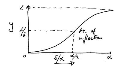
Two parabolas used with inflection point at mid-range.
Let y = aδ2 + bδ + c Parabolic curve
Y’ = 2aδ + b
Y’’ = 2a
Y’’’ = 0
For the first parabolic curve 0 ≤ δ/α ≤ 0.5
δ/α = 0 => y(0) = 0 => c = 0
y’(0) = 0 => b = 0
Thus y = aδ2
At point of inflection δ/α = 0.5 and y = L/2
L/2 = a α2/4 giving a = 2L/α2
Therefore: y = 2L(δ/α)2
y’ = 4Lδ/α2
y’’ = 4L/α2
y’’’ = 0 Accel. Const
This is just true go to the point of inflection.
Maximum slope occurs at the point of inflection δ/α = 0.5
y’ max = 4Lδ/α2 = 2L/α
Now take from the point of inflection on: For the second parabolic curve 0.5 ≤ δ/α ≤ 1 and the equation of the curve is the same as before: y = aδ2 + bδ + c
At the end of the rise δ/α = 1 => y(1) = L = aδ2 + bδ + c Eqn. 1
y’(1) = 0 = 2aδ + b Eqn. 2
Matching with the slope at the point of inflection: δ/α = 0.5 this gives
y’ = 2L/α = 2aδ + b = a α + b Eqn. 3
Solving 1. 2. and 3 simultaneously gives:
a = - 2L/α2
b = 4 L/α
c = -L
Displacement equations for the second parabolic section are:
y = L(1 – 2(1- δ/α)2) Displacement
y’ = 4L/α (1 – δ/α) Velocity
y’’ = -4L/α2 Acceleration
y’’’ = 0 Jerk
Throughout this example when differentiating to obtain velocity, acceleration and jerk they have been considered with respect to angle and not with respect to time. They should be scaled by ω, ω2 and ω3 to make them correct w.r.t. time. In general for a constant speed shaft, the kinematic derivatives of the follower motion are equal to the time derivatives of the follower if the kinematic derivatives are scaled by ω, ω2, and ω3 respectively.

Source: http://www.worldcolleges.info/sites/default/files/enggnotes/cams.doc
Web site to visit: http://www.worldcolleges.info
Author of the text: indicated on the source document of the above text
If you are the author of the text above and you not agree to share your knowledge for teaching, research, scholarship (for fair use as indicated in the United States copyrigh low) please send us an e-mail and we will remove your text quickly. Fair use is a limitation and exception to the exclusive right granted by copyright law to the author of a creative work. In United States copyright law, fair use is a doctrine that permits limited use of copyrighted material without acquiring permission from the rights holders. Examples of fair use include commentary, search engines, criticism, news reporting, research, teaching, library archiving and scholarship. It provides for the legal, unlicensed citation or incorporation of copyrighted material in another author's work under a four-factor balancing test. (source: http://en.wikipedia.org/wiki/Fair_use)
The information of medicine and health contained in the site are of a general nature and purpose which is purely informative and for this reason may not replace in any case, the council of a doctor or a qualified entity legally to the profession.
The texts are the property of their respective authors and we thank them for giving us the opportunity to share for free to students, teachers and users of the Web their texts will used only for illustrative educational and scientific purposes only.
All the information in our site are given for nonprofit educational purposes