
INTRODUCTION
As we have seen, capacitance is a function of plate area, plate separation and dielectric permittivity, so for a given capacitance in a given space a large plate area, small spacing and high permittivity are the main requirements. There are a variety of problems associated with the construction of capacitors for practical circuit use and these may be roughly divided into two groups.
Electrical problems
The main electrical problem is that of dielectric strength but there are also problems incurred with production of heat due to electron transfer. This is particularly important at high frequencies where there is a continual and rapid change of plate polarity.
Mechanical Problems
The mechanical problems of capacitor design depend largely upon three factors: the capacity required, the maximum working voltage at which it is to be used and whether it is to be employed on dc and low frequencies or at high frequencies.
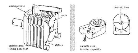
Variable Air Capacitors Fig. 5
Air has a unity permittivity and negligible loss at all frequencies, but because of the plate area problem, air-spaced capacitors are extremely bulky relative to the capacitance they can provide. They are normally only used in tuning circuits where a variation of capacity is obtained by turning a set of movable plates into or out of a set of fixed plates. Examples of variable air spaced capacitors are shown in Fig 5.
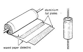 Wound Capacitors
The plates are two long strips of aluminium foil separated by two strips of waxed paper and then wound up into a roll as shown in Fig. 6. Electrical connection is made to each of the metal strips and the whole assembly is then sealed into a metal tube which is then marked and covered with a plastic insulating sleeve.
Many modern capacitors use a plastic film instead of waxed paper as the dielectric. Plastics in common use are polystyrene, polyethylene terephthalate (PET) and mylar. Most plastic dielectric capacitors have a higher insulation resistance than paper capacitors but are restricted in operation to frequencies below about 100 MHz because of dielectric losses.
Fig 6
Mica Capacitors
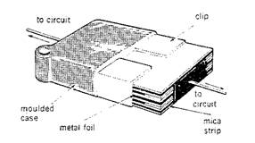
These are high quality capacitors with mica acting as the dielectric. Older types are constructed from layers of metal foil interleaved with layers of mica (Fig. 7). Alternate metal foils are joined together and connected to the two terminals. The assembly is then packed, often in a moulded plastic or resin case. Some very high stability capacitors are made with silver deposited directly on one side of each mica strip. They are expensive but may be used at very high frequencies (up to about 1GHz). Fig. 7
Ceramic Capacitors
 These are high quality devices, made in various forms, each type of construction depending on the value of capacitance required. Fig. 8 shows typical construction which is to have a disc of ceramic material (such as barium titanate), on the opposite faces of which the silver electrodes are deposited. They are widely used for tuning and timing purposes at frequencies up to about 5GHz.
Fig. 8
Electrolytic Capacitors
Fig. 9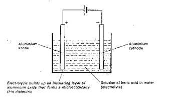
Electrolytic capacitors make use of the anodising action of a boric acid electrolyte on aluminium electrodes as shown in Fig. 9. The extreme thinness of the dielectric film so formed permits extremely high capacity capacitors to be made in very compact form. Unfortunately, the dielectric film only exists as long as the applied emf is correctly polarised. Incorrect connection or connection to an ac source will destroy the film and therefore the capacitor.
All electrolytic capacitors use a film of a metallic oxide as the dielectric. Construction (Fig. 10) is similar to the paper capacitor with aluminium foil for the plates separated by paper impregnated with an electrolyte such as ammonium borate. Electrolytic capacitors are manufactured with working voltages from 6V to 500V, although accuracy is generally not very high.
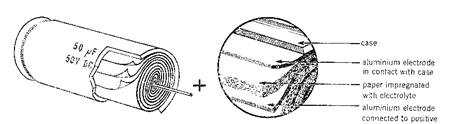
Fig. 10
Source: https://moodle.cambria.ac.uk/pluginfile.php/54150/mod_resource/content/0/E_E_Principles/Capacitor_construction.doc
Web site to visit: https://moodle.cambria.ac.uk
Author of the text: indicated on the source document of the above text
If you are the author of the text above and you not agree to share your knowledge for teaching, research, scholarship (for fair use as indicated in the United States copyrigh low) please send us an e-mail and we will remove your text quickly. Fair use is a limitation and exception to the exclusive right granted by copyright law to the author of a creative work. In United States copyright law, fair use is a doctrine that permits limited use of copyrighted material without acquiring permission from the rights holders. Examples of fair use include commentary, search engines, criticism, news reporting, research, teaching, library archiving and scholarship. It provides for the legal, unlicensed citation or incorporation of copyrighted material in another author's work under a four-factor balancing test. (source: http://en.wikipedia.org/wiki/Fair_use)
The information of medicine and health contained in the site are of a general nature and purpose which is purely informative and for this reason may not replace in any case, the council of a doctor or a qualified entity legally to the profession.
The texts are the property of their respective authors and we thank them for giving us the opportunity to share for free to students, teachers and users of the Web their texts will used only for illustrative educational and scientific purposes only.
All the information in our site are given for nonprofit educational purposes