
CASTING
Casting is basically melting a solid material, heating to a special temperature, and pouring the molten material into a cavity or mold, which is in proper shape. Casting has been known by human being since the 4th century B.C.
Today it is nearly impossible to design anything that cannot be cast by means of one or more of the available casting processes. However, as with other manufacturing processes, best results and economy can be achieved if the designer understands the various casting processes and adapts his designs so as to use the process most efficient.
1. Solidification of Melts
When a melt is poured into a colder mold, metal in contact with the mold solidifies in the form of roughly equiaxed fine grains, because cooling rates are high, and the wall induces heterogeneous nucleation.
Solidification proceeds by the growth of a few favorably oriented nuclei, in the direction of heat extraction. This leads to be observed columnar structure. Because of the preferred growth direction of the large grains, the casting will have very anisotropic properties.
Since most metals shrink on solidification, the liquid meniscus gradually drops and a shrinkage cavity (pipe) remains.
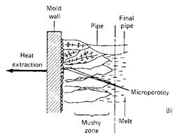
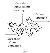
Figure 1. Solidification proceeds with (a) the growth of columnar grains in pure metals but, (b) with the growth of dendrites in solid solutions. (c) Dendrites grow in crystallograhically favorable directions [2].
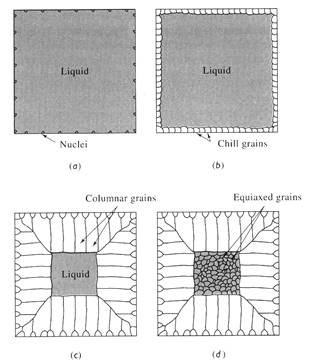
Figure 2. Development of the macrostructure of a casting during solidification: (a) Nucleation begins, (b) the chill zone forms, (c) preferred growth produces the columnar zone, and (d) additional nucleation creates the equiaxed zone.
2. Casting Materials
Although some non-metals are cast, the process is primary importance in the production of metal products. The metals most frequently cast are iron, steel, aluminium, brass, bronze, magnesium, and certain zinc alloys.
3. Casting Procedure
In all casting processes six basic factors are involved. These are as follows:
4. CASTING PROCESSES
Much of the development that has taken place in the foundry industry has been directed toward meeting these six objectives with greater economy. Six major casting processes currently are used. These are:
6.1. SAND CASTING
Sand casting is a flexible, inexpensive process. Sand is used as the mold material. The sand grains, mixed with small amounts of other materials to improve the moldability and cohesive strength, are packed around a pattern that has the shape of the desired casting. Products covering a wide range of sizes and detail can be made by this method. A new mold must be made for each casting, and gravity usually is employed to cause the metal to flow into the mold. The process is not so accurate as die casting or investment casting.
6.2. PLASTER-MOLD CASTING
Plaster-mold casting is somewhat similar to sand casting in that only one casting is made and then the mold is destroyed, in this case the mold is made out of a specially formulated plaster. 70 to 80% gypsum and 20 to 30% fibrous strengtheners. Water is added to make a creamy s1urry. This process is limited to non-ferrous metals, because ferrous metals react with sulphur in gypsum. The core boxes are usually made form brass, plastics, or aluminium.
6.3. INVESTMENT CASTING
Casting processes in which the pattern is used only once are variously referred to as "lost-wax" or "precision-casting" processes. In any case they involve making a pattern of the desired form out of wax or plastics (usually polystyrene). A metal flask is placed around the assembled patterns and refractory mold slurry is poured to support the patterns and form the cavities. A vibrating table equipped with a vacuum pump is used to eliminate all the air from the mold. After the mold material has set and dried, the pattern material is melted and allowed to run out of the mold.
When the metal is cooled, the investment material is removed by means of vibrating hammers or by tumbling. As with other castings, the gates and risers are cut off and ground down.
6.4. CENTRIFUGAL CASTING
Centrifugal casting consists of having sand, metal, or ceramic mold that is rotated at high speeds. When the molten metal is poured into the mold it is thrown against the mold wall, where it remains until it cools and solidifies. The process is being increasingly used for such products as cast-iron pipes, cylinder liners, gun barrels, pressure vessels, brake drums gears, and flywheels. The metals used include almost all castable alloys.
Because of the relatively fast cooling time, centrifugal castings have a fine gram size. There is a tendency for the lighter non-metallic inclusions slag particles, and dross to segregate toward the inner radius of the casting where it can be easily removed by machining. Due to the high purity of the outer skin, centrifugally cast pipes have a high resistance to atmospheric corrosion.
6.5. PERMANENT-MOLD CASTING PROCESSES
The process utilizes a metal casting die in conjunction with metal or sand cores. Molten metal is introduced at the top of the mold that has two or more parts, using only the force of gravity. After solidification, the mold is opened and the casting ejected. The mold is reassembled and the cyc1e is repeated. The molds are either metal or graphite and, consequently, most permanent-mold castings are restricted to lower melting point nonferrous metals and alloys.
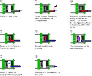
6.6. DIE CASTING
Die casting differs from ordinary permanent-mold casting in that the molten metal is forced into the molds by pressure and held under pressure during solidification. Most die castings are made from nonferrous metals and alloys, but substantial quantities of ferrous die castings now are being produced. Because of the combination of metal molds or dies, and pressure, fine sections and excellent detail can be achieved, together with tong mold life. Special zinc-, copper-, and aluminium-base alloys suitable for die casting have been developed which have excellent properties, thereby contributing to the very extensive use of the process.
Because die-casting dies usually are made from hardened tool steel, they are expensive to make. In addition, the die sections must contain knockout pins, which eject the casting.
6.7. SQUEEZE CASTING
Squeeze casting, also known as liquid-metal forging, is a process by which molten metal solidifies under pressure within c1osed dies positioned between the plates of a hydraulic press. Squeeze casting consists of metering liquid metal into a preheated, lubricated die and forging the metal while it so1idifies. The load is applied shortly after the metal begins to freeze and is maintained until the entire casting has solidified. Casting ejection and handling are done in much the same way as in closed die forging.
The applied pressure and the instant contact of the molten metal with the die surface produce a rapid heat transfer condition that yields a pore-free fine-grain casting with mechanical properties approaching those of a wrought product.
The squeeze casting process is easily automated to produce near-net to net shape high-quality components.
The process was introduced in the United States in 1960 and has since gained widespread acceptance.
Advantages of squeeze casting
With the current emphasis on reducing materials consumption through virtually net shape processing and the demand for higher-strength parts for weight savings, the emergence of squeeze casting as a production process has given materials and process engineers a new alternative to the traditional approaches of casting and forging. By pressurizing liquid metals while they solidify, near-net shape can be achieved in sound fully dense castings. Improved mechanical properties are additional advantages of squeeze cast parts. The micro structural refinement and integrity of squeeze cast products are desirable for many critical applications.
Squeeze casting has been successfully applied to a variety of ferrous and nonferrous alloys in traditionally cast and wrought compositions. Applications include aluminum alloy pistons for engines and disk brakes; automotive wheels, truck hubs, barrel heads; brass and bronze bushings and gears; steel missile components and differential pinion gears; and a number of parts in cast iron, including ductile iron mortar shells.
7. CORE DESIGN
Cores are mold parts used to shape internal holes and cavities. They are also fortification parts of molds where wearing occurs. These parts are made of sand and organic-inorganic bonders such as cereal meals, dextrin, sodium silicate, cement etc. Some properties of cores must have are the followings:
Internal Cavity Projecting Parts Mold Fortification
8. MELTING AND CASTING
During melting process chemical content of the raw material is determined. Alloying is achieved at this stage where raw materials are in liquid phase. Most known furnace types to prepare the liquid metal are:
The most difficult and important part of melting & alloying process is the removal of impurities from the liquid. These operations differ according to the type of furnace.
9. Design of Castings
When designing casting the most important consideration is the effect of shrinkage during cooling. Other important factors include metal flow, and porosity.
Some general rules are,
- Avoid sharp corners - they can lead to hot tearing during cooling.
- Use fillets cautiously - they lead to stresses as they shrink a radius of 1/8" to 1" are acceptable.
- Avoid large masses - they will cool more slowly, and can lead to pores and cavities in the final part. Cores can be used to hollow out these large volumes. Metal padding `chills' can also be placed inside the mold near large masses to help increase cooling rates.
- Use uniform cross sections -this will keep the cooling rate relatively uniform and avoid stresses.
- Avoid large flats - large flat areas tend to warp.
- Allow some give as the part cools - by allowing the shrinkage of one part to deform another slightly, the internal stresses will be reduced. Figures of 1-2% shrinkage are common.
- Put parting lines near corners - this will hide the flash.
- Straight Parting Lines - where possible a straight parting line will allow easier mold making.
- Use a Draft angle - A small angle of 0.5-2° on the vertical walls will make the pattern easier to remove.
- Machining Allowances - allow excess material for later machining of critical dimensions
- Wide Tolerances - because shrinkage occurs as the part cools it will be very hard to keep tight tolerances.
- Stress Relieve When Needed - Stress relief can reduce the effects of non-uniform cooling.
- Avoid thin sections - These will be very hard to fill, and will tend to harden quickly.
10. When to Use the Casting Process
Design and manufacturing engineers must often decide when it is advantageous to use the casting process or when it may be better to use some other method of fabrication. Given below is a list of some of the main considerations that may be used in choosing the casting process.
There are also times when it is not advantageous to use the casting process, as follows:
REFERENCES
Source: http://www.learneasy.info/MDME/MEMmods/MEM30007A/processing/07_Processing.doc
Web site to visit: http://www.learneasy.info/
Author of the text: indicated on the source document of the above text
From http://www.efunda.com/processes/processes_home/process.cfm
And The Open University Walton Hall, Milton Keynes MK7 6AA
Hot Forming Processes Die Casting Sand Casting Extrusion Forging Powder Metallurgy Centrifugal |
Heat Treatments |
Cold Forming |
Surface Treatments |
Machining |
Rapid Prototyping |
Sheet Metal |
|
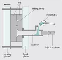
The metal is injected into the mold under high pressure of 10-210Mpa (1,450-30,500) psi . This gives a more uniform part, good surface finish and dimensional accuracy, (around 0.2 % of casting dimensions). Can almost eliminate post-machining on some parts. Die casting molds (called dies in the industry) are expensive as they are made from hardened steel and take a long time to make. There are two types of die-casting - cold chamber or hot chamber process.
• Cold chamber process: The molten metal is ladled into the cold chamber for each shot. There is less time exposure of the melt to the plunger walls or the plunger. This is particularly useful for metals such as Aluminum, and Copper (and its alloys) that alloy easily with Iron at the higher temperatures (which will wear out the plunger cylinder).
The largest die-castings are about 20 kg for Magnesium (35 kg for Zinc). Large castings tend to have greater porosity problems, due to entrapped air, and the melt solidifying before it gets to the furthest extremities of the die-cast cavity. Vacuum die casting redues porosity.
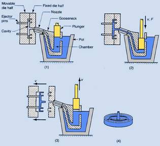
• Hot chamber process: The pressure chamber is connected to the die cavity is immersed permanently in the molten metal. The inlet port of the pressurizing cylinder is uncovered as the plunger moves to the open (unpressurized) position. This allows a new charge of molten metal to fill the cavity and thus can fill the cavity faster than the cold chamber process. The hot chamber process is used for metals of low melting point and high fluidity such as tin, zinc, and lead that tend not to alloy easily with steel at their melt temperatures.
Common Alloys in Die Casting
High temperature metals such as iron and steel cannot be die-cast. Aluminum, Zinc and Brass alloys are the materials predominantly used in die-casting.
Aluminum is cast at a temperature of 650 ºC. Pure Aluminum shrinks too much, and suffers hot cracking. It is alloyed with Silicon, which increases melt fluidity, reduces machinability. E.g. Silicon 9%, Copper 3.5%. Silicon increases the melt fluidity, reduces machinability, Copper increases hardness and reduces the ductility. High silicon alloy is used in automotive engines for cylinder castings - e.g.17% Silicon for high wear resistance. Common aluminum alloys for die casting are summarized as follows:
Zinc can be made to close tolerances and with thinner walls than Aluminum, due to its high melt fluidity. Zinc is alloyed with Aluminum (4%), which adds strength and hardness. The casting is done at a fairly low temperature of 425 ºC (800 ºF) so the part does not have to cool much before it can be ejected from the die. This, in combination with the fact that Zinc can be run using a hot chamber process allows for a fast fill, fast cooling (and ejection) and a short cycle time. Zinc alloys are used in making precision parts such as sprockets, gears, connector housings, and fine detail such as carburettor bodies. Chrome plateable.
Copper alloys (brass) are used in plumbing, electrical and marine applications where corrosion and wear resistance is important.
Design: The largest die-castings are about 20 kg for Magnesium (35 kg for Zinc). Large castings tend to have greater porosity problems, due to entrapped air, and the melt solidifying before it gets to the furthest extremities of the die-cast cavity. Vacuum die casting redues porosity.
Design: Keep uniform wall thicknesses. Avoid heavy sections, they cause cooling problems like trapped gases and porosity. Use maximum radii on all corners to avoid stress concentration. Allow draft - see table above. Keep core shapes simple.
Minimum wall thicknesses and minimum draft angles for die casting:
Material |
Min. Thickness |
Min. Draft Angle (º) |
Aluminum alloys |
0.9 mm |
0.5 |
Zinc alloys |
0.6 mm |
0.25 |
Copper alloys (Brass) |
1.25 mm |
0.7 |
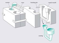
A metal mould, such as cast iron, with cores made from metal or sand. Cavity surfaces are coated with a thin layer of heat resistant material such as clay or sodium silicate. Moulds are pre-heated to 200 ºC before the metal is poured into the cavity. Good for production run of 1000 or more parts. Materials include aluminum, magnesium and brass and their alloys. Typical parts include gears, splines, wheels, gear housings, pipefittings, fuel injection housings, and automotive engine pistons.
Design rules: Minimum wall thicknesses (e.g. 3mm for lengths under 75 mm), radius (inside radius = nominal wall thickness, outside radius = 3 x nominal wall thickness), draft angles (1 to 3º on outside surfaces, 2 to 5º on inside surfaces). Typical tolerances are 2 % of linear dimensions. Surface finish ranges from 2.5 µm to 7.5 µm. Typical part sizes range from 50 g to 70 kg.
Sand casting is used to make large parts (typically Cast Iron, but also Bronze, Brass, Aluminum). Molten metal is poured into a mold cavity formed out of sand (natural or synthetic).
The cavity in the sand is formed by using a pattern (a slightly larger duplicate of the real part), which are typically made out of wood, sometimes metal. Cores are for holes, made of sand - often hardened by a binder. The riser tells you the mould is full (stop pouring!) and to supply metal to the shrinking casting as it initially cools.
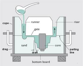
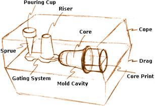
The drag is filled with sand around the pattern, and with the core print, the cores, and the gating system (which are usually near the parting line). The empty cope is then assembled to the drag, and the sand is poured on the cope half, covering everything, and compacted by vibration or by flinging the sand. Next, the cope is carefully removed from the drag, and the pattern is extracted without damaging the sand mould cavity. (Needs draft around 1° and a smooth pattern surface)
The molten metal is poured in the pouring cup connected by a vertical sprue to the horizontal runner. This connect to the casting by gates - which need to be cut off later. vents are also needed to allow air to escape.
The pattern is made oversize to allow for the metal contraction.
Metal |
Pattern Oversize Factor (each direction) |
Finish Allowance |
Min Wall |
Aluminum |
1.08 - 1.12 |
0.5 to 1.0 % |
4.75 (0.187) |
Copper alloys |
1.05 - 1.06 |
0.5 to 1.0 % |
2.3 (0.094) |
Gray Cast Iron |
1.10 |
0.4 to 1.6 % |
3.0 (0.125) |
Nickel alloys |
1.05 |
0.5 to 1.0 % |
N/A |
Steel |
1.05 - 1.10 |
0.5 to 2 % |
5 (0.20) |
Magnesium alloys |
1.07 - 1.10 |
0.5 to 1.0 % |
4.0 (0.157) |
Malleable Irons |
1.06 - 1.19 |
0.6 to 1.6 % |
3.0 (0.125) |
Sand castings generally have a rough surface sometimes with surface impurities, and surface variations. A machining (finish) allowance is made for this type of defect.
The process can be used to make complex shapes becasue the sand cores are destroyed to remove the casting. (e.g. Complex 3D shapes such as this automobile cylinder head). Also good for large custom parts like large pump housings or ship propellors.
The Egyptians used it to make gold jewelry thousands of years ago. Intricate shapes can be made with high accuracy, and it can be used for high temperature metals and alloys that are hard to machine.
A wax pattern of the part is made, then dipped in refractory slurry, which coats the wax pattern and forms a skin. This is dried and the process of dipping in the slurry and drying is repeated until a robust thickness is achieved. After this, the entire pattern is placed in an oven and the wax is melted away and the ceramic is baked at high temperature to harden it. This mould can be filled with the molten metal. Since the pattern can be melted out, very intricate parts and undercuts can be made. The wax pattern itself can be made by machining, casting, or rapid prototyping. the pattern can also be made of thermoplastic foam.
Before casting, the mold is pre-heated to about 1000 ºC (1832 ºF) to remove any residues of wax, harden the binder. The pour in the pre-heated mold also ensures that the mold will fill completely. Pouring can be done using gravity, pressure or vacuum conditions.
View this animation: Flash Animation of Investment Casting Process
Tolerances of 0.5 % of length are routinely possible, and as low as 0.15 % is possible for small dimensions. Castings can weigh from a few grams to 35 kg, although the normal size ranges from 200 g to about 8 kg. Normal minimum wall thicknesses are about 1 mm, or even 0.5 mm for easy casting alloys.
Metals include Aluminum alloys, Bronzes, tool steels, stainless steels, various cast irons and steels and precious metals. Post machining can sometimes be avoided altogether because of the close tolerances that can be achieved.
This uses a permanent mold rotated about its axis at high speeds (300 to 3000 rpm) as the molten metal is poured. The molten metal is centrifugally thrown towards the inside mold wall, where it solidifies after cooling.
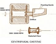
Only cylindrical shapes can be produced with this process. Size limits are upto 3 m diameter and 15 m long, wall thickness can be 2.5 mm to 125 mm. The tolerances on the OD can be as good as 2.5 mm and on the ID can be 3.8 mm.
Typical materials that can be cast with this process are iron, steel, stainless steels, and alloys of aluminum, copper and nickel. Typical applications are pipes, boilers, pressure vessels, flywheels, cylinder liners and other large round parts.
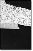
When a liquid metal cools and begins to solidify in a mould, grains (crystals) of the metal start to form, both on the mould walls and in the bulk of the liquid metal. The way they grow is shown schematically in Figure 25(a). As the metal solidifies, it forms tree-like dendrites (from dendron: the Greek for tree). This structure is maintained after the casting is fully solidified, as can be seen from Figure 25(b), which shows a typical casting microstructure. (The image is created by polishing the surface of the metal, immersing it for a short while in a dilute acid and viewing it under an optical microscope.) In addition to the dendritic structure, there are two other common defects that can be found in a cast microstructure: particles of impurities known as inclusions, and porosity which is small holes in the casting.

Castings (a) dendritic formation (b) a typical cast microstructure
Some inclusions can be removed by heating the casting to a temperature somewhat below its melting point to anneal it and ‘dissolve’ the inclusions in the metal; but the porosity is more difficult to remove. The porosity occurs because the casting has shrunk on solidification. Most materials contract on solidification (water is one of the few liquids that expands on solidification, so that ice floats on water; bad news for the Titanic, but good news for polar bears) and this shrinkage is not always uniform, so that substantial holes and voids can be left in the casting. This reduces the load-bearing capability of the component, and in highly stressed products, where the full strength of the material is being utilised, voids can lead to failure. The shrinkage on solidification can be large, and is generally a greater effect than the thermal contraction of the solid material as it cools to room temperature.
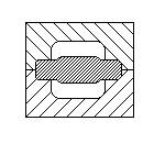
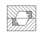
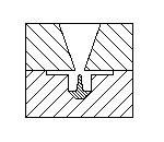
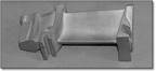
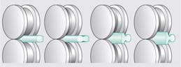
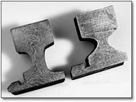
In many casting processes, runners and risers are used as reservoirs of molten metal to prevent voids from developing in the casting as it solidifies and shrinks.A section through a gravity-die casting (below) clearly shows the effects of this contraction. The chimney-like feature is the runner, down which liquid aluminium alloy was poured into the mould. There is a hollow in the top of the runner caused by liquid flowing from the runner into the mould as the casting solidified. As well as the hollow at the top, you can see some holes in the runner and one hole within the casting itself. The runners and risers will later be cut off and discarded.
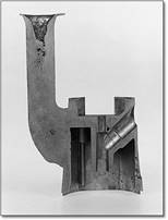
Section though a gravity die-cast microscope body
Forming processes involve shaping materials which are solid - if the yield stress is low enough. One way to lower a metal’s yield stress is to heat it up (e.g. blacksmith working on a horseshoe).
Stress-strain curves give indication of formability. This described two properties, yield stress (or flow stress) and ductility. Remember that the yield stress is a good measure of the strength of a ductile material.
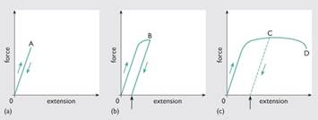
The effect of progressively straining a material
The steel can be loaded elastically up to its yield strength, point A. Removing the load below this level leaves no permanent extension, i.e. the steel can return to its original size and shape. If the material is taken above its yield strength, say to point B, then even after unloading, the steel is permanently deformed. What’s more, when the material is then reloaded, it has to be loaded to a stress equal to point B – i.e. more than its original yield point at A – before it continues to flow. This is called work hardening: the plastic deformation causes an increase in strength (and hardness). But further plasticity is then limited. If the material is loaded to point C, where about half the available plasticity has been ‘used up’, then on reloading only the remaining plasticity from C to D is available before the material breaks.
However, all is not lost. The work hardening effect can be eliminated, and the original, softer, condition restored, by annealing the metal. This involves heating to a temperature where the atoms in the material become more mobile, so that the material softens. This type of process is widely applied in manufacturing whenever a part-formed product has been worked so much that it is in danger of cracking; and is why blacksmiths keep reheating a horseshoe during working. The precise mechanism of softening varies from material to material but it occurs for most materials at a high homologous temperature. Homologous temperature,T H, is the ratio of the operating temperature of a material to its melting point (in kelvins, K).
In the context of forming, if a metal is ‘hot worked’, it is deformed at a temperature where there is virtually no work hardening, and this resoftening effect carries on continuously. Very high strains can be imposed during the forming process.
Conversely ‘cold working’ does result in work hardening, so that the material gets harder the more it is deformed. ‘Cold working’ does not literally mean cold, though – it is all measured relative to the homologous temperature. The rule of thumb usually employed is that cold forming occurs at homologous temperatures below 0.3 and hot forming occurs at homologous temperatures above 0.6. In between the two, there is a region known as warm forming. This means that if tungsten is worked at 1000°C (1273K) it is being cold formed, as its melting point is 3410°C (3683K). Conversely, at room temperature, solder can be hot worked! So working temperature is all about being able to deform the metal without failure.
As the stresses needed to make solids flow are considerably higher than those required for liquids, forming processes normally require a lot of energy and strong, resilient tooling. As a result, forming is often economically viable only for production volumes large enough to justify the high tooling costs.
So when do we use forming rather than casting? There are three reasons why, for many products, forming is preferable to casting.
The principle of this process is very similar to squeezing toothpaste from a tube. Material is forced through a shaped hollow die in such a way that it is plastically deformed and takes up the shape of the die. The hole in the die can have almost any shape, so if the die is circular, for example, a wire or rod is produced.
It is also possible to produce hollow sections using extrusion. In this case, the die contains a short piece (or mandrel) in the shape of the hole. This mandrel is attached to the die by one or more ‘bridges’. As the extruded material encounters the bridges it is forced to separate, but it flows around the bridges and joins up again, much the same as water flowing around the piers of a bridge. Figure 30 shows such a ‘bridge die’. This works successfully even for processing of solid metals.
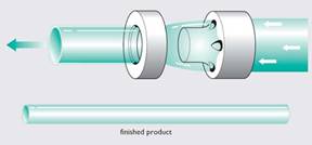
Extrusion bridge die making a hollow section product. Note that in the picture the die has been split to show the material passing through it. In reality, the die and the ring fit together, with a gap for the extruded material to flow through.
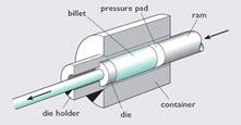
Extrusion can be used on most materials that can plastically flow as a solid, and solid metals and alloys are frequently extruded. To reduce the stresses required, and therefore the size and cost of the extrusion machine, and also to ensure hot working conditions, a metal is usually extruded at a high homologous temperature, usually between 0.65 and 0.9. This allows large changes in the shape of the material – and hence large strains – without fracture. During metal extrusion the raw material in the form of a metal ingot, known as the billet, is heated and pushed through the die by a simple sliding piston or ram.
In rolling, material is passed through the gap between two rotating rollers that squeeze the material as it passes between them. The rolled material emerges with a thickness roughly equal to the gap between the rollers. When the rollers are cylindrical, rolling produces material in the form of plate or sheet. Sheet steel and aluminium for the bodies of cars and domestic appliances is made this way. Rolled sheet is often termed a ‘semifinished’ product, as it requires further processing to shape it into the final product.
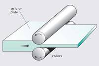
Rolling
Rolling is not restricted to flat sheets, though. If the desired product has a contoured surface, then by using profiled rollers the contour can be rolled on. If the surface pattern needs to be deeper than is possible during one rolling pass then multiple rollers can be used; for example, railway tracks are made by rolling between pairs of progressively deeper contoured rollers. The various stages for rails are shown below.
Stages in rolling railway track
In common with other forming processes, metals may be hot or cold rolled. The significant differences between hot and cold rolling are in the amount of energy needed to roll a given volume of material and in the resulting microstructures. The cooler the metal, the higher its yield stress and the more energy has to be supplied in order to shape it. As in extrusion, metals in large lumps are often hot rolled at homologous temperatures above 0.6. At this temperature the yield stress and work hardening are reduced. Railway lines require hot rolling in order to achieve the large change in shape from a rectangular bar. However, a major disadvantage of hot rolling is that the surface of the material becomes oxidised by the air, resulting in a poor surface finish.
If the metal is ductile then it may be cold rolled using smaller strains. This has some advantages: the work hardening at these temperatures can give the product a useful increase in strength. During cold rolling, oxidation is reduced and a good surface finish can be produced by using polished rollers. So, cold rolling is a good finishing treatment in the production of plate and sheet. The sheets of steel for car bodies are finished by cold rolling because a good surface finish is essential in this product.
Forging is typified by countless generations of blacksmiths with their hammers and anvils. Besides still being used for special ‘hand-made’ items, this type of forging is similar to that used, on a somewhat larger scale, for the initial rough shaping of hot metal ingots.
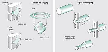
Forging processes
In closed die forging components are made in one action, being squeezed between upper and lower shaped dies There is usually a small amount of excess material which is forced out of the die cavity as flash. This must then be removed from the component. The force needed to close the dies together is dependent both on the size of the component and the temperature, since as we noted earlier, the flow stress reduces as the forging temperature increases. The quality of the surface finish of the forging decreases with temperature, however, because of increased surface oxidation.
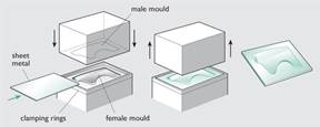
Sheet metal forming of a car body panel
A cheap gear and the original.
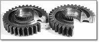
An unused gear (on the right) showing the ring of teeth which were breaking off – the smaller teeth at the top of the gear. The gear on the left was a used gear where the teeth have been worn away.
Sections etched to reveal flow lines: (left) original forged gear, inner teeth worn now; (right) new gear, inner teeth full profile.
What difference is there in the flow lines in these two sections?
In the new gear they all run parallel to the axis and, if this were made of wood you would expect them to break off easily. In the old gear the flow lines are in a looped, radial pattern tending to run at right angles to the gear’s axis. If you look carefully at the small teeth you will see that they run pretty well at right angles to the direction of the flow lines in the new gear.
The original gears had been forged before the teeth were cut, whereas the replacements had been machined directly from round bar. The flow lines tell us that the old gears had started off as a length of round bar about twice as long as the gear is thick, but of smaller diameter. This was hot forged to squash it down, causing the outside to spread out so that the shape finished up with a much larger diameter and shorter length than when it started. This was done specifically to develop the flow line pattern you can observe. When the teeth were cut, the grain flow was oriented at right angles to the applied bending stresses in service. The teeth were thus as tough as they could be for this type of steel and the flow lines were oriented in directions which imparted the maximum resistance to failure.
In contrast, the new gears had been machined from stock of the full diameter the gear required. There was no forging, so the flow lines remained parallel to the gear axis.
The result was that the flow lines in the teeth were in the most unfavourable orientation to resist fatigue and brittle fracture. This is why they broke off so quickly under service loads, despite having the same hardness (and tensile strength) as the original gears.
Essentially all powder processing routes involve filling a mould with powder (this is similar to filling the mould during casting, as powders flow as slurries), which is then compressed in between dies to begin the process of reducing the space between the powder particles. The powder compact produced is then heated to a high temperature to produce a solid component.
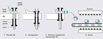
Powder processing
The process of sintering starts with the material in powder form and is used for a wide variety of materials, especially those with properties which preclude shaping by melting and casting. Examples are ceramics such as alumina and silicon nitride; brittle metals with high melting temperatures (over 2300K), such as tungsten; and the polymer PTFE (polytetrafluoroethylene), which has a viscosity too high to suit other moulding methods.
The starting powder is mixed with a lubricant/binder and is then moulded to shape by compressing it in a die to form what is called a ‘green’ compact. Although this is highly porous, it has enough rigidity to support its own weight and permit gentle handling. The compact is then sintered – that is, heated at a high temperature and sometimes under pressure – for a prolonged time. During sintering, the powder particles coalesce (small particles join together to form larger ones) and grow to fill the pore spaces. The compact shrinks correspondingly, forming a solid homogeneous (uniform) mass in the shape of the original mould. Depending on the sintering process used, the final component can have various degrees of porosity and therefore strength, as any porosity can act as defects in the form of cracks. Very high temperatures and/or pressures during sintering are used to minimise porosity.
In powder processing, the volume of the workpiece does not stay constant. As the powder fuses together, most of the spaces between the powder disappear and the volume of the finished component is considerably reduced.
Sintering is sometimes economically competitive with alternative methods of shaping; for volume production of complex parts it is often cheaper than machining. A wide variety of components can be manufactured using powder processing: these can range from processing domestic ceramics for applications such as bathroom sinks to the insulating sleeve in a spark plug.
Cutting is the most common manufacturing process. Cutting is often used as a secondary or finishing process where the product to be cut will have been made by one of the processes described earlier. This could be to;
Many parts are produced entirely by machining - especially if the basic shape derives from solid rod or plate. There is poor material utilisation of cutting processes, but this can often be tolerated and automation can make cutting attractive at much higher production volumes.
In industry, cutting was traditionally performed on large machines with a whole host of specialist names such as lathes, mills, broachers, shapers and many others. Each type of machine was capable of one particular method of cutting. Somewhat confusingly, these cutting machines are collectively known as machine tools and the processes are known as machining. The last few decades have seen substantial growth in the use of flexible, computer controlled machining centres (Figure 41) that incorporate both tool- and workpiece-changing facilities. The introduction of such machines, together with their reduced need for a skilled workforce to operate them, have reduced operating costs so that cutting can now be considered for production volumes that would previously be considered uneconomic.
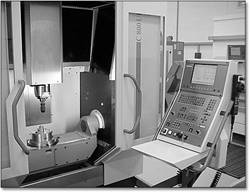
Typical computer-controlled machining centre
During any machining operation, the cutting tool comes in contact with the material to be cut, called the workpiece. The cutting machine has to hold both the tool and workpiece, and to move one relative to the other for the cutting operation to be performed.
All cutting processes are essentially complex arrangements of a simple single-point cutting operation: a saw blade is just a collection of single-point cutting tools; sandpaper is lots of single-point cutting grits stuck onto a piece of paper.
When the cutting tool is brought into contact with the workpiece, it detaches a thin layer of unwanted material (the ‘chip’). The tip of the tool is shaped like a wedge so that the faces of the tool are always inclined to the machined surface of the workpiece in order to limit the area of rubbing between tool and workpiece. This rubbing is undesirable because it wastes energy and it causes the tool to wear at an increased rate.
Chip formation during machining
In deforming the chip, work is done by the tool on the workpiece and more than 90 per cent of this energy is transformed into heat. This heat is concentrated in a small volume of the workpiece near the tip of the tool. The actual temperature profile near the cutting point depends on the thermal and mechanical properties of both the tool and workpiece but it is common for temperatures to reach 700°C locally, even when liquid coolants are used.
At these temperatures, a state of partial seizure or bonding exists at the tool/workpiece interface, as the chip starts to weld to the tool. This is highly undesirable, since it contributes both to wear of the tool and to the consumption of energy during machining. Lubrication does help relieve the situation, but the careful design of the cutting tool is of paramount importance. There are specific tool geometries and cutting angles for different materials which help to keep temperatures and energies to a minimum while they are being cut.
The main attraction of machining as a shaping process is its ability to produce almost any shape accurately. However, machining requires expensive capital equipment and can also produce a lot of waste material, and for large production volumes it often proves more expensive than alternative methods of shaping.
There are basically three types of tool material:
Tool steels have been available since the turn of the nineteenth century, and are still the mainstay of tool materials. They are alloys of iron and carbon with additions of elements such as chromium, tungsten, molybdenum, titanium and vanadium. These elements improve the cutting properties of the steel and the response to heat treatment.
Metal carbide tools, which are also often called hard metal tools, are made by mixing together powders of cobalt (chemical symbol Co) and a metal carbide (usually tungsten carbide, WC). These are then sintered using powder processing techniques. The particles of carbide (which are hard and very strong, even at machining temperatures) form the cutting surfaces of the tool and the function of the cobalt is simply to hold together all the carbide particles. You can see from Figure 44 that the microstructure consists of particles of metal carbide, embedded in cobalt. This is a good example of how physically mixing two materials having differing property profiles can produce a composite material which has more useful properties than either of its constituents.
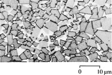
Figure 44: Microstructure of a WC/Co hard metal tool
Finally, ceramic tools usually consist of aluminium oxide (Al2O3), sometimes with small additions of magnesium oxide (MgO). They are also made from blended powders using the sintering process. These tools retain good strength and chemical stability at high temperatures. More specialist tools can also be made from ceramic composite materials (by mixing two or more ceramic materials) and also diamond, which is used for machining non-ferrous and very hard materials.
These ceramic materials are also used as the tooling in grinding processes. These use a high-speed rotating wheel made of a porous abrasive material which removes a small layer of material as it passes across the workpiece (Figure 45). In this case there are many thousands of small cutting edges where the hard abrasive particles, such as diamond or aluminium oxide, protrude from the surface of the wheel. Grinding is used to make surfaces (usually flat or cylindrical) with a good finish on hard materials, as the size of cut and therefore the chip is very small. As the amount of material removed during grinding is minor, grinding is normally considered as a finishing process.
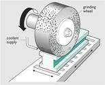
Figure 45: Grinding
This is for cutting sheet material. Usually CNC
In general terms, there are three basic methods of joining material together:
They are versatile, easy to use, allow dismantling of the product and permit different materials to be joined with ease. Mechanical joining also allows movement of components relative to one another, for example, by the use of hinges and bearings.
Mechanical joints do have disadvantages – the fasteners join at discrete points and do not, by themselves, seal the joint against the passage of liquids and gases. The hole that the fastener goes through in a mechanical joint is a potential weak spot and failure often occurs at these sections.
Brazing is defined as the joining of metals using a filler rod which melts at temperatures above 450°C but below the melting temperature of the metals being joined. Typical features of the brazing process are:
And because of these differences, the brazing process has several distinct advantages over welding:
Soldering is defined as a brazing-type operation where the filler metal has a melting temperature below 450°C. The bond strength is relatively low compared to brazing. The ‘traditional’ solder alloy is based on a tin/lead mixture, but lead-free alloys are becoming more commonplace.
The essential feature of adhesive joining is that two parts are joined by placing a liquid between them, which then solidifies. The strength of the joint depends both on the strength of bond between the parts and the adhesive layer, and the strength of the adhesive layer itself.
The word ‘adhesive’ is usually taken to mean a type of glue. Adhesives now come in a vast array of different types; some stick in seconds (cyanoacrylate – Superglue), some take a day or so to cure (thermosetting epoxies), others stay permanently in a soft flexible state, like silicone adhesives. Thermosetting glues, like thermosetting plastics, are made by mixing together two ingredients, a ‘resin’ and a ‘hardener’, usually in liquid form, which react chemically to form a solid.
The major advantages of adhesive bonding are:
The major disadvantages of adhesive bonding are:
For successful soldering or adhesion, the ‘glue’ material must ‘wet’ the surfaces of the two objects to be joined. You can see the contrast between wetting and non-wetting when washing up greasy breakfast plates. When the plates are covered with oil and fat, water just runs off without sticking. This contrasts with what happens when the fat is removed with hot water and detergent: the plate then retains a thin covering of water. We say that water is ‘wetting’ the clean glazed surface.
Successful joining by solders or adhesives usually requires that the surfaces to be joined are completely clean. This can be achieved by using either mechanical or chemical techniques. The mechanical method uses abrasion to clean the surface, while the chemical methods for preparing metals typically use acidic solutions which etch the surface, as well as degreasing it with solvents. After cleaning the surface it is vital that recontamination does not occur from oxidation and airborne pollution. In particular, when heat is applied during brazing and soldering, oxidation can rapidly take place; in this case a flux can be applied which prevents oxygen from reaching the prepared surface. Abrading also has the advantage that the surface is roughened, thereby increasing the surface area which enhances the contact area of the joint.
In highly deformable materials, such as metals and thermoplastics, the above aims can be achieved by solid-state welding, that is, forcing the two surfaces together so that plastic deformation makes their shapes conform to one another. At the same time the surface layers are broken up, allowing the intimate contact needed to fuse the materials without necessarily melting them. This was the principle of the first way known to weld metals – by hammering the pieces together whilst hot. It is not always essential for the parts to be hot; ductile metals such as gold can be pressure welded at ambient temperatures. Processes that join without melting the material are called solid-state welding.
Solid-state welding can be carried out in various ways. For example, two metal sheets laid over each other can be welded together by rolling – ‘roll bonding’. Bimetallic strips for thermostats are made this way. Deformation of the surfaces can also be done in more exotic ways such as rubbing the two surfaces against one another (friction welding) or by using explosives to fold one sheet of metal against another (explosive welding).
In solid-state welding, there is a small melted zone, but the melted matter is usually ‘squeezed out’ when the parts are pushed together, so the join is a solid-state one. Commonly polyethylene gas pipes are welded using heat and pressure. In this case a heated plate is used to generate the heat on the two surfaces. Once hot, the plate is removed and the pipes are forced together under pressure, thereby forming a welded joint. The heat sealing of thermoplastics works on the same principle. Two layers of plastic sheet that are to be joined are overlapped and compressed between heated tools. This forces the materials together and the joint is made because of the intimate contact between the surfaces.
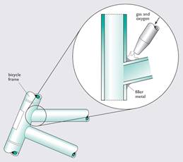
In fusion welding, the parts to be joined are brought together, melted and fused to each other. In some processes the interface is filled with a molten substance, supplied by a filler rod that is similar in composition to the materials being joined.
During fusion welding the areas that are being joined comprise an intimate mixture of parent material, and filler rod (if one is used), within the welded zone. In all methods of fusion welding, heat must be supplied to the joint in order to melt the material. Inevitably, temperature profiles are created and the resulting differential expansions and contractions can cause distortion, and in extreme cases, the formation of cracks, in the assembly. As welds are, in fact, small castings, welds contain both the microstructure and porosity endemic in cast material.
Soldering and brazing can minimise some of these problems, as the parent material is not melted, so temperature profiles are not as great. But in brazing and soldering there is a discrete join between the materials as opposed to an intimate mixture of material in welding; welding is by far the strongest of the processes.
See my website here; http://check.itgo.com
Electroplating, hot-dip plating, plasma spraying, mechanical coating, sputtering,
Surface heat treatment - carburizing, nitriding,
Other: titanium nitride etc.
Much of this material comes from The Open University Walton Hall, Milton Keynes MK7 6AA
Source: http://www.learneasy.info/MDME/MEMmods/MEM30007A/processing/07_Processing.doc
Web site to visit: http://www.learneasy.info/
Author of the text: indicated on the source document of the above text
If you are the author of the text above and you not agree to share your knowledge for teaching, research, scholarship (for fair use as indicated in the United States copyrigh low) please send us an e-mail and we will remove your text quickly. Fair use is a limitation and exception to the exclusive right granted by copyright law to the author of a creative work. In United States copyright law, fair use is a doctrine that permits limited use of copyrighted material without acquiring permission from the rights holders. Examples of fair use include commentary, search engines, criticism, news reporting, research, teaching, library archiving and scholarship. It provides for the legal, unlicensed citation or incorporation of copyrighted material in another author's work under a four-factor balancing test. (source: http://en.wikipedia.org/wiki/Fair_use)
The information of medicine and health contained in the site are of a general nature and purpose which is purely informative and for this reason may not replace in any case, the council of a doctor or a qualified entity legally to the profession.
The texts are the property of their respective authors and we thank them for giving us the opportunity to share for free to students, teachers and users of the Web their texts will used only for illustrative educational and scientific purposes only.
All the information in our site are given for nonprofit educational purposes