
If the proper safety procedures are not adhered when working on Clutch Systems this could lead to serious injury \health problems e.g. Respiratory problems to personnel.
Instruction is given in the proper safety procedures applicable to working on clutch systems which include Safe use of:
Refer to motor risk assessments, Environmental policy, and Material Safety Data Sheets (MSDS)
 A clutch connects and disconnects one rotating mechanical component from another. An automobile clutch transmits torque from the engine to the transmission, and the driver uses a release mechanism to control the flow of the torque between them.
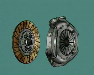
Most light vehicles use a single-plate, friction-type disc, with two friction facings attached to a central hub, splined to accept the transmission input shaft.
The friction facings are clamped between the flat surface of the engine flywheel and a spring-loaded pressure-plate, bolted to its outer edge.
Most light vehicles use a single-plate clutch to transmit torque from the engine to the transmission input shaft. The flywheel is the clutch driving member. The clutch unit is mounted on the flywheel’s machined rear face, so that the unit rotates with the flywheel. The clutch unit consists of a friction-type disc, with two friction facings and a central splined hub.
A pressure plate assembly, consisting of, pressed steel cover, pressure plate with a machined flat face, segmented diaphragm spring, release bearing and operating fork.
The friction disc is sandwiched between the machined surfaces of the flywheel and the pressure plate when the pressure plate is bolted to the outer edge of the flywheel face.
The clamping force on the friction facings is provided by the diaphragm spring. Unloaded, it is a dished shape. As the pressure plate cover tightens, it pivots on its fulcrum rings, and flattens out to exert a force on the pressure plate, and the facings.
The transmission input shaft passes through the centre of the pressure plate. Its parallel splines engage with the internal splines of the central hub, on the friction disc.
With engine rotation, torque can now be transmitted from the flywheel through the friction disc, to the central hub, and to the transmission. A group of torsional springs located between the clutch hub and lining dampens driveline shocks and vibration.
When the clutch pedal is depressed, the movement is transferred through the operating mechanism, to the operating fork and the release bearing.
The release bearing moves forward and pushes the centre of the diaphragm spring towards the flywheel.
The diaphragm pivots on its fulcrum rings causing the outer edge to move in the opposite direction and act on the pressure-plate retraction clips. The pressure plate disengages, and drive is no longer transmitted. Releasing the pedal allows the diaphragm to re-apply its clamping force and engage the clutch, and drive is restored.
In light vehicle applications the pressure plate is normally a diaphragm type and is serviced as an assembly.
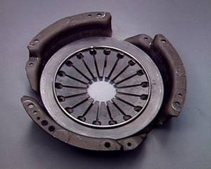
It consists of a pressed steel cover, a pressure plate with a machined flat surface, a number of spring steel drive straps, and the diaphragm spring.
This diaphragm is located inside the clutch cover on 2 fulcrum rings, held by a number of rivets passing through the diaphragm.
The pressure plate is connected to the cover by the spring steel drive straps, riveted to the cover at one end, and to projecting lugs on the plate, at the other.
Retraction clips hold the pressure plate in contact with the outer edge of the diaphragm. During clutch operation, they move the plate away from the flywheel.
The driven centre-plate is also called a clutch disc or friction disc.
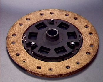
The driven plate has a pair of friction facings, of wire-reinforced asbestos-free composition, carried on waved spring steel segments, which are riveted to a steel disc.
The central alloy-steel splined hub is separate. Drive is transmitted from the disc to the hub through heavy torsional coil springs or rubber blocks. This spring hub arrangement dampens torsional vibrations from the engine. It also absorbs shock loads imposed on the drive line by sudden or violent clutch engagement.
Stops limit the radial movement of the hub against the spring force. A moulded friction washer between the hub and spring retaining plate also acts as a dampener.
The waved spring steel segments causes the facings to spread slightly when the clutch is disengaged – then compress as it is engaged. This has a cushioning effect and provides smooth engagement.
The clutch release bearing can be a thrust-type angular contact ball bearing, supported on a carrier. It slides on a hub or sleeve extending from the front of the transmission.
The bearing carrier locates on the clutch release fork. Moving the fork brings the bearing thrust face into contact with the pressure plate fingers. This causes the bearing to rotate, and absorb the rotary motion of the fingers, against the linear motion of the fork. The bearing is packed with lubricant during manufacture and requires no periodic maintenance during its service life.
 In modern light-diesel technology we are seeing much greater horsepower and torque gains sometimes coupled to better fuel economy.
To eliminate excessive transmission gear rattle, making driving comfortable at any speed, reduce gear change/shift effort.
Transmissions in light duty trucks diesel powered vehicles have a by default a heightened sensitivity to fluctuating torsional inputs. This results in a strong torsional resonance or vibration that occurs during operation of the vehicle within normal driving ranges.
By providing a vibration dampening action that is superior to the normal dampening actions in a normal clutch arrangement the vehicle can be operated for longer periods without long term damage.
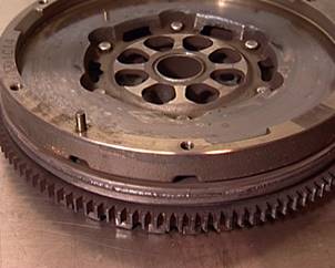
The dual mass flywheel construction relocates the damper from the driven disc to the engine flywheel. This repositioning dampens engine torsional vibrations more than is possible with standard clutch disc dampening technology.
The function of the Dual Mass Flywheels or DMF is to isolate torsion crankshaft spikes created by diesel engines with high compression ratios. By eliminating the torsion spikes, the system eliminates any potential damage to the transmission gear teeth. If the DMF was not used the torsional frequencies could damage to the transmission.
 Movement at the pedal pad is transferred through an operating mechanism, to the clutch assembly on the rear of the flywheel.
This mechanism may be mechanical or hydraulic.
Mechanical systems may use a system of levers but cable operation gives more flexibility and is more common.
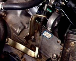
In hydraulic clutch control, the pedal acts on a master cylinder, connected by a hydraulic pipe and flexible hose, to a slave cylinder, mounted on the clutch housing.
The slave cylinder operates the clutch release fork. With clutch hydraulic systems it is important that no air is in the system as this will compress and not allow pressure to the transmitted to the clutch release fork. Therefore it is important to bleed the system and this should be done using manufactures procedures.
In physics and engineering, mechanical advantage (MA) is the factor by which a machine multiplies the force put into it.
In physics, a lever is a rigid object that is used with an appropriate fulcrum or pivot point to multiply the mechanical force that can be applied to another object. This is also termed mechanical advantage (ma) and is one example of the principle of moments.
The force applied (at end points of the lever) is proportional to the ratio of the length of the lever arm measured between the fulcrum and application point of the force applied at each end of the lever.
There are three classes of levers representing variations in the location of the fulcrum and the input and output forces.
Examples: First-class levers
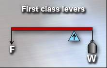 Seesaw
Examples: Second-class levers
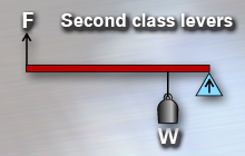 Wheelbarrow
Examples: Third-class levers
 Human arm
 The Principle of Moments states that when a body is in equilibrium, then the sum of the clockwise moments about any point equals the sum of the anticlockwise moments about same point.
Hydraulic clutch systems use an incompressible fluid, such as brake fluid to transmit forces from one location to another within the fluid. Most automobiles use hydraulics in the braking systems also. Pascal’s law states that when there is an increase in pressure at any point in a confined fluid, there is an equal increase at every other point in the container.

Hydraulic pressure is transmitted through liquid. Since liquid is effectively incompressible, pressure applied to a liquid is transmitted without loss throughout the liquid. In a braking system, this allows a force applied to the brake pedal to act upon the brakes at the wheels.
Hydraulic pressure can transmit increased force. Since pressure is force per unit area, the same pressure applied over different areas can produce different forces - larger and smaller.
Pressure is the application of force to a surface, and the concentration of that force in a given area. A finger can be pressed against a wall without making any lasting impression; however, the same finger pushing a thumbtack can easily damage the wall, even though the force applied is the same, because the point concentrates that force into a smaller area.
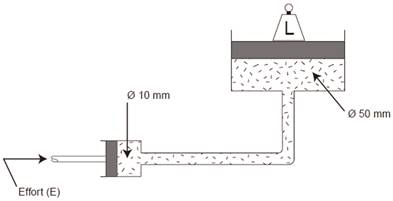
In a typical garage jack you might have a plunger of 10mm diameter pumping into a ram having a diameter of 50mm. This would give a force ratio of 25:1.
Area of Plunger = Þr2
= 3.14 x (52)
= 78.5mm2
Area of Ram = Þr2
= 3.14 x (252)
= 1962.5mm2
![]()
![]() Force ratio Area of Ram 1962.5 = 25
Force ratio Area of Ram 1962.5 = 25
Area of Plunger 78.5
F.R = 25:1
In a brake system the master cylinder and slave cylinder relationship are of such a size to give a force ratio of 4:1 (approx.)
Friction is a force that resists the movement of one surface over another. In some instances it can be desirable; but more often is not desirable. It is caused by surface rough spots that lock together. These spots can be microscopically small, which is why even surfaces that seem to be smooth can experience friction. Friction can be reduced but never eliminated.
Friction is always measured for pairs of surfaces, using what is called a coefficient of friction.
The coefficient of friction (also known as the frictional coefficient or the friction coefficient) is a scalar value used to calculate the force of friction between two bodies. The coefficient of friction depends on the materials used -- for example, ice on metal has a very low coefficient of friction (they rub together very easily), while rubber on pavement has a very high coefficient of friction (they do not rub together easily). It is interesting to note that, contrary to common belief, the force of friction is invariant to the size of the contact area between the two objects. This means that friction does not depend on the size of the objects. The force of friction is always exerted in a direction that opposes movement. For example, a chair sliding to the right across a floor experiences the force of friction in the left direction.
Static friction occurs when the two objects are not moving relative to each other (like a desk on the ground). The coefficient of static friction is typically denoted as μ. The initial force to get an object moving is often dominated by static friction.
Kinetic friction occurs when the two objects are moving relative to each other and rub together (like a sled on the ground). The coefficient of kinetic friction is typically denoted as μ, and is usually less than the coefficient of static friction.
Is when two objects are rubbing against each other. Putting a book flat on a desk and moving it around is an example of sliding friction.
The maximum torque transmitted by a clutch is governed by the friction material of the lining, the mean radius of the linings (both sides) and the spring pressure of the pressure plate. Oil or grease on the lining which would reduce the friction action, or a weak or broken springs in the pressure plate would cause the clutch to slip under pressure.
It can now be clearly seen that Lining A has a greater mean radius by 10% than lining B. This means that lining A can transmit more torque by as much as 10% The example of the lining width is intended to dispel a belief that an increase in area allows more torque to be transmitted. A suitable width of lining is one which is sufficiently narrow to give the largest mean radius but not so narrow as to allow rapid wear or fade to occur.
For a clutch to transmit torque without slip there are four factors to be considered.
Torque = Spur
(s)Two surfaces. Spring Pressure (N) .Coefficient of Friction (μ), 100 mm = 1m (Radius)

Fault |
Cause |
Clutch slip |
Worn Lining |
Clutch drag Drive plate not becoming free when pedal is depressed |
Distorted drive plate |
Clutch judder |
Worn lining or protruding rivets. |
Source: http://local.ecollege.ie/Content/APPRENTICE/liu/hvm_notes/M4U1.doc
Web site to visit: http://local.ecollege.ie/
Author of the text: indicated on the source document of the above text
If you are the author of the text above and you not agree to share your knowledge for teaching, research, scholarship (for fair use as indicated in the United States copyrigh low) please send us an e-mail and we will remove your text quickly. Fair use is a limitation and exception to the exclusive right granted by copyright law to the author of a creative work. In United States copyright law, fair use is a doctrine that permits limited use of copyrighted material without acquiring permission from the rights holders. Examples of fair use include commentary, search engines, criticism, news reporting, research, teaching, library archiving and scholarship. It provides for the legal, unlicensed citation or incorporation of copyrighted material in another author's work under a four-factor balancing test. (source: http://en.wikipedia.org/wiki/Fair_use)
The information of medicine and health contained in the site are of a general nature and purpose which is purely informative and for this reason may not replace in any case, the council of a doctor or a qualified entity legally to the profession.
The texts are the property of their respective authors and we thank them for giving us the opportunity to share for free to students, teachers and users of the Web their texts will used only for illustrative educational and scientific purposes only.
All the information in our site are given for nonprofit educational purposes