
Objectives:
Chapter 1 - Numerical Control Fundamentals
![]()
Computer Numerical Control (CNC) is a specialized and versatile form of Soft Automation and its applications cover many kinds, although it was initially developed to control the motion and operation of machine tools.
Computer Numerical Control may be considered to be a means of operating a machine through the use of discrete numerical values fed into the machine, where the required 'input' technical information is stored on a kind of input media such as floppy disk, hard disk, CD ROM, DVD, USB flash drive, or RAM card etc. The machine follows a predetermined sequence of machining operations at the predetermined speeds necessary to produce a workpiece of the right shape and size and thus according to completely predictable results. A different product can be produced through reprogramming and a low-quantity production run of different products is justified.
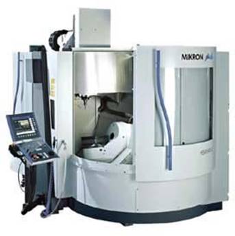
Fig.1-1 CNC Machine Centre (Courtesy of Agie Charmilles)
The definition of CNC given by Electronic Industry Association (EIA) is as follows:
A system in which actions are controlled by the direct insertion of numerical data at some point. The system must automatically interpret at least some portion of this data.
In a simple word, a CNC system receives numerical data, interpret the data and then control the action accordingly.
Open loop systems have no access to the real time data about the performance of the system and therefore no immediate corrective action can be taken in case of system disturbance. This system is normally applied only to the case where the output is almost constant and predictable. Therefore, an open loop system is unlikely to be used to control machine tools since the cutting force and loading of a machine tool is never a constant. The only exception is the wirecut machine for which some machine tool builders still prefer to use an open loop system because there is virtually no cutting force in wirecut machining.
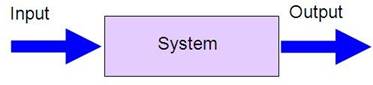
Fig.1-2(a) Block Diagram of an Open Loop System
In a close loop system, feed back devices closely monitor the output and any disturbance will be corrected in the first instance. Therefore high system accuracy is achievable. This system is more powerful than the open loop system and can be applied to the case where the output is subjected to frequent change. Nowadays, almost all CNC machines use this control system.
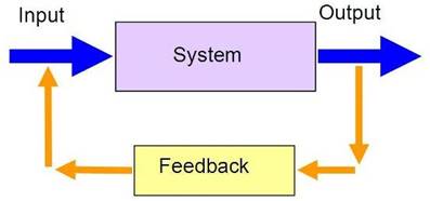
Fig.1-2(b) Block Diagram of a Close Loop System
A CNC system consists of the following 6 major elements:
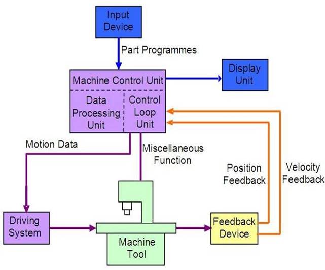
Fig.1-3 Working Principles of CNC Machines
Floppy disk is a small magnetic storage device for CNC data input. It has been the most common storage media up to the 1970s, in terms of data transfer speed, reliability, storage size, data handling and the ability to read and write. Furthermore, the data within a floppy could be easily edited at any point as long as you have the proper program to read it. However, this method has proven to be quite problematic in the long run as floppies have a tendency to degrade alarmingly fast and are sensitive to large magnetic fields and as well as the dust and scratches that usually existed on the shop floor.
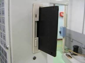
Fig.1-4 Floppy Disk Drive on a CNC machine
A USB flash drive is a removable and rewritable portable hard drive with compact size and bigger storage size than a floppy disk. Data stored inside the flash drive
are impervious to dust and scratches that enable flash drives to transfer data from place to place. In recent years, all computers support USB flash drives to read and write data that make it become more and more popular in CNC machine control unit.
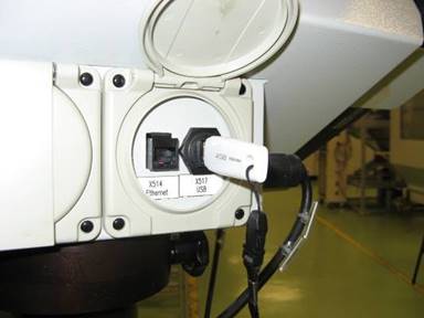
Fig.1-5 USB Flash Drive on a CNC machine
The data transfer between a computer and a CNC machine tool is often accomplished through a serial communication port. International standards for serial communications are established so that information can be exchanged in an orderly way. The most common interface between computers and CNC machine tools is referred to the EIA Standard RS-232. Most of the personal computers and CNC machine tools have built in RS232 port and a standard RS-232 cable is used to connect a CNC machine to a computer which enables the data transfer in reliable way. Part programs can be downloaded into the memory of a machine tool or uploaded to the computer for temporary storage by running a communication program on the computer and setting up the machine control to interact with the communication software.
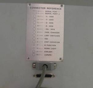
Fig.1-6 Serial communication port on a CNC machine
Direct Numerical Control is referred to a system connecting a set of numerically controlled machines to a common memory for part program or machine program storage with provision for on-demand distribution of data to the machines. (ISO 2806:1980) The NC part program is downloaded a block or a section at a time into
the controller. Once the downloaded section is executed, the section will be discarded to leave room for other sections. This method is commonly used for machine tools that do not have enough memory or storage buffer for large NC part programs.
Distributed Numerical Control is a hierarchical system for distributing data between a production management computer and NC systems. (ISO 2806:1994) The host computer is linked with a number of CNC machines or computers connecting to the CNC machines for downloading part programs. The communication program in the host computer can utilize two-way data transfer features for production data communication including: production schedule, parts produced and machine utilization etc.
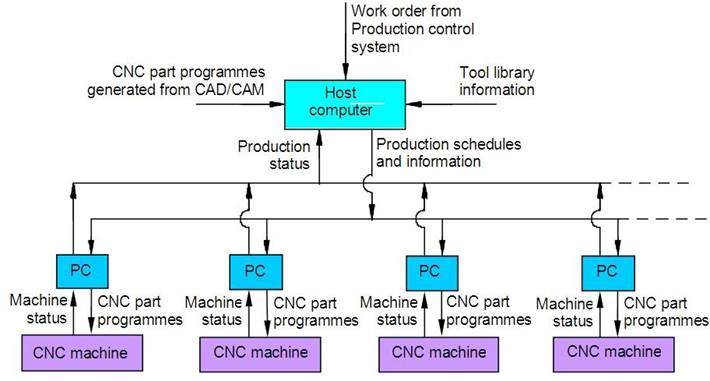
Fig.1-7 Serial communication in a Distributed Numerical Control system
Due to the advancement of the computer technology and the drastic reduction of the cost of the computer, it is becoming more practical and economic to transfer part programmes between computers and CNC machines via an Ethernet communication cable. This media provides a more efficient and reliable means in part programme transmission and storage. Most companies now built a Local Area Network (LAN) as their infrastructure. More and more CNC machine tools provide an option of the Ethernet Card for direct communication within the LAN.
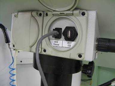
Fig.1-8 Ethernet port on a CNC machine
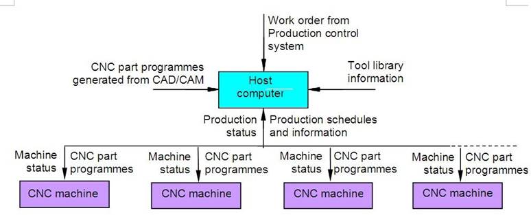
Fig.1-9 Ethernet network in a Distributed Numerical Control system
Part programmes can be input to the controller via the keyboard. Built-in intelligent software inside the controller enables the operator to enter the required data step by step. This is a very efficient way for preparing programmes for relatively simple workpieces involving up to 2½ axis machining.
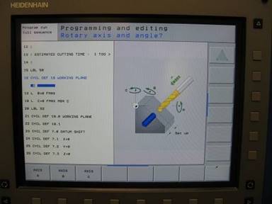
Fig.1-10 Conversational Programming in a CNC controller
The machine control unit is the heart of the CNC system. There are two sub-units in the machine control unit: the Data Processing Unit (DPU) and the Control Loop Unit (CLU).
On receiving a part programme, the DPU firstly interprets and encodes the part programme into internal machine codes. The interpolator of the DPU then calculate the intermediate positions of the motion in terms of BLU (basic length unit) which is the smallest unit length that can be handled by the controller. The calculated data are passed to CLU for further action.
The data from the DPU are converted into electrical signals in the CLU to control the driving system to perform the required motions. Other functions such as machine spindle ON/OFF, coolant ON/OFF, tool clamp ON/OFF are also controlled by this unit according to the internal machine codes.
This can be any type of machine tool or equipment. In order to obtain high accuracy and repeatability, the design and make of the machine slide and the driving leadscrew of a CNC machine is of vital importance. The slides are usually machined to high accuracy and coated with anti-friction material such as PTFE and Turcite in order to reduce the stick and slip phenomenon. Large diameter recirculating ball screws are employed to eliminate the backlash and lost motion. Other design features such as rigid and heavy machine structure; short machine table overhang, quick change tooling system, etc also contribute to the high accuracy and high repeatability of CNC machines.
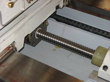
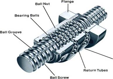
Fig.1-11(a) Ball Screw in a CNC machine Fig.1-11(b) Ball screw structure
The driving system is an important component of a CNC machine as the accuracy and repeatability depend very much on the characteristics and performance of the driving system. The requirement is that the driving system has to response accurately according to the programmed instructions. This system usually uses electric motors although hydraulic motors are sometimes used for large machine tools. The motor is coupled either directly or through a gear box to the machine leadscrew to moves the machine slide or the spindle. Three types of electrical motors are commonly used.
This is the most common type of feed motors used in CNC machines. The principle of operation is based on the rotation of an armature winding in a permanently energised magnetic field. The armature winding is connected to a commutator, which is a cylinder of insulated copper segments mounted on the shaft. DC current is passed to the commutator through carbon brushes, which are connected to the machine terminals. The change of the motor speed is by varying the armature voltage and the control of motor torque is achieved by controlling the motor's armature current. In order to achieve the necessary dynamic behaviour it is operated in a closed loop system equipped with sensors to obtain the velocity and position feedback signals.
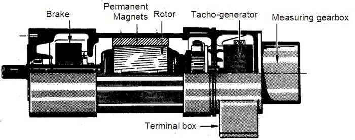
Fig.1-12 DC Servo Motor (Courtesy of Flexible Automation)
In an AC servomotor, the rotor is a permanent magnet while the stator is equipped with 3-phase windings. The speed of the rotor is equal to the rotational frequency of the magnetic field of the stator, which is regulated by the frequency converter.
AC motors are gradually replacing DC servomotors. The main reason is that there is no commutator or brushes in AC servomotor so that maintenance is virtually not required. Furthermore, AC servos have a smaller power-to-weight ratio and faster response.
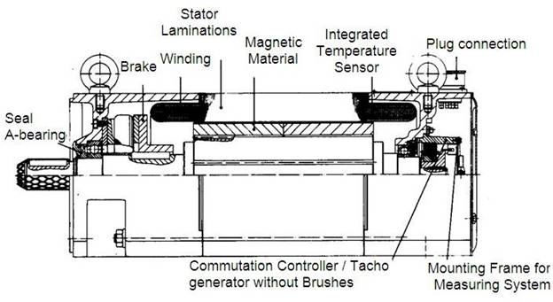
Fig.1-13 AC Servo Motor (Courtesy of Flexible Automation)
A stepping motor is a device that converts the electrical pulses into discrete mechanical rotational motions of the motor shaft. This is the simplest device that can be applied to CNC machines since it can convert digital data into actual mechanical displacement. It is not necessary to have any analog-to-digital converter nor feedback device for the control system. They are ideally suited to open loop systems.
However, stepping motors are not commonly used in machine tools due to the following drawbacks: slow speed, low torque, low resolution and easy to slip in case of overload. Examples of stepping motor application are the magnetic head of floppy-disc drive and hard disc drive of computer, daisy-wheel type printer, X-Y tape control, and CNC EDM Wire-cut machine.
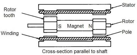
Fig.1-14 Stepping Motor (Courtesy Real-Time Microcomputer)
A linear electric motor is an AC rotary motor laid out flat. The same principle used to produce torque in rotary motors is used to produce force in linear motors. Through the electromagnetic interaction between a coil assembly and a permanent magnet assembly, the electrical energy is converted to linear mechanical energy to generate a linear motion. As the motion of the motor is linear instead of rotational, therefore it is called linear motor. Linear motors have the advantages of high speeds, high precision and fast response. In the 1980s,
machine tool builders started using linear motors with the common motion control servo drives in the machine tool design.
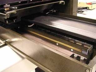
Fig.1-15 Linear Motor (Courtesy of Renishaw)
Among different designs of linear motors, permanent magnet brushless motors demonstrate a high force density, high maximum speed, and stable force constant. The lack of a brushed commutator assembly has the advantages of fewer maintenance, higher reliability and better smoothness.
An iron core brushless linear motor is similar to a conventional brushless rotary motor slit axially and then rolled out flat. The unrolled rotor is a stationary plate consisting of magnets tiled on an iron back plate and the unrolled stator is a moving coil assembly consisting of coils wound around a laminated steel core. Coil windings are typically connected in conventional 3 phase arrangement and commutation is often performed by Hall-effect sensors or sinusoidal. It has high efficiency and good for continuous force.
An ironless linear motor consists of a stationary U shaped channel filled with permanent magnets tiled along both interior walls. A moving coil assembly traverses between two opposing rows of magnets. Commutation is done electronically either by Hall-effect sensors or sinusoidal. The ironless linear motor has the advantages of lower core mass, lower inductance and no cogging for smooth motion as the ironless motors have no attractive force between the frameless components.

Fig.1-16 Ironcore and Ironless Linear Motor (Courtesy of ETEL)
In order to have a CNC machine operating accurately, the positional values and speed of the axes need to be constantly updated. Two types of feed back devices are normally used, positional feed back device and velocity feed back device.
There are two types of positional feed back devices: linear transducer for direct positional measurement and rotary encoder for angular or indirect linear measurement.
Linear Transducers - A linear transducer is a device mounted on the machine table to measure the actual displacement of the slide in such a way that backlash of screws; motors, etc would not cause any error in the feed back data. This device is considered to be of the highest accuracy and also more expensive in comparison with other measuring devices mounted on screws or motors.
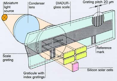
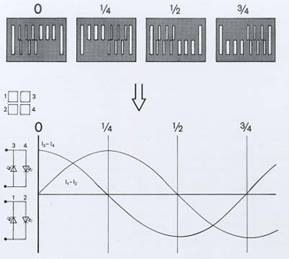
Fig.1-17 Linear Transducer (Courtesy of Heidenhain)
Rotary Encoders - A rotary encoder is a device mounted at the end of the motor shaft or screw to measure the angular displacement. This device cannot measure linear displacement directly so that error may occur due to the backlash of screw and motor etc. Generally, this error can be compensated for by the machine builder in the machine calibration process.

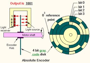
Fig.1-18 Incremental and Absolute Rotary Encoder
The actual speed of the motor can be measured in terms of voltage generated from a tachometer mounted at the end of the motor shaft. DC tachometer is essentially a small generator that produces an output voltage proportional to the speed. The voltage generated is compared with the command voltage corresponding to the desired speed. The difference of the voltages can is then used to actuate the motor to eliminate the error.
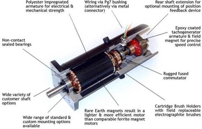
Fig.1-19 Tachogenerator (Courtesy of Callan)
The Display Unit serves as an interactive device between the machine and the operator. When the machine is running, the Display Unit displays the present
status such as the position of the machine slide, the spindle RPM, the feed rate, the part programmes, etc.
In an advanced CNC machine, the Display Unit can show the graphics simulation of the tool path so that part programmes can be verified before the actually machining. Much other important information about the CNC system can also displayed for maintenance and installation work such as machine parameters, logic diagram of the programmer controller, error massages and diagnostic data.
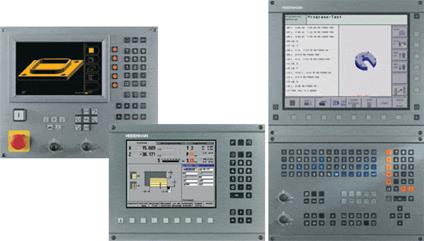
Fig.1-20 Display Unit for CNC machines (Courtesy of Heidenhain)
CNC machines are widely used in the metal cutting industry and are best used to produce the following types of product:
the development stage of a prototype
Some common types of CNC machines and instruments used in industry are as following:
Source: https://www.lnjpitchapra.in/wp-content/uploads/2020/04/file_5ea57729c2fa7.docx
Web site to visit: https://www.lnjpitchapra.in
Author of the text: indicated on the source document of the above text
If you are the author of the text above and you not agree to share your knowledge for teaching, research, scholarship (for fair use as indicated in the United States copyrigh low) please send us an e-mail and we will remove your text quickly. Fair use is a limitation and exception to the exclusive right granted by copyright law to the author of a creative work. In United States copyright law, fair use is a doctrine that permits limited use of copyrighted material without acquiring permission from the rights holders. Examples of fair use include commentary, search engines, criticism, news reporting, research, teaching, library archiving and scholarship. It provides for the legal, unlicensed citation or incorporation of copyrighted material in another author's work under a four-factor balancing test. (source: http://en.wikipedia.org/wiki/Fair_use)
The information of medicine and health contained in the site are of a general nature and purpose which is purely informative and for this reason may not replace in any case, the council of a doctor or a qualified entity legally to the profession.
The texts are the property of their respective authors and we thank them for giving us the opportunity to share for free to students, teachers and users of the Web their texts will used only for illustrative educational and scientific purposes only.
All the information in our site are given for nonprofit educational purposes