1.0 INTRODUCTION TO STRUCTURAL ENGINEERING
1.1 GENERAL INTRODUCTION
Structural design is a systematic and iterative process that involves:
- Identification of intended use and occupancy of a structure – by owner
- Development of architectural plans and layout – by architect
- Identification of structural framework – by engineer
- Estimation of structural loads depending on use and occupancy
- Analysis of the structure to determine member and connection design forces
- Design of structural members and connections
- Verification of design
- Fabrication & Erection – by steel fabricator and contractor
- Inspection and Approval – by state building official
Ideally, the owner and the architect, the architect and the engineer, and the engineer and the fabricator/contractor will collaborate and interact on a regular basis to conceive, develop, design, and build the structure in an efficient manner. The primary responsibilities of all these players are as follows:
- Owner - primary responsibility is deciding the use and occupancy, and approving the architectural plans of the building.
- Architect - primary responsibility is ensuring that the architectural plan of the building interior is appropriate for the intended use and the overall building is aesthetically pleasing.
- Engineer – primary responsibility is ensuring the safety and serviceability of the structure, i.e., designing the building to carry the loads safely and ___________.
- Fabricator – primary responsibility is ensuring that the designed members and connections are fabricated economically in the shop or field as required.
- Contractor/Erector - primary responsibility is ensuring that the members and connections are economically assembled in the field to build the structure.
- State Building Official – primary responsibility is ensuring that the built structure satisfies the appropriate building codes accepted by the Govt.
1.2 STRUCTURAL DESIGN
- Conceptually, from an engineering standpoint, the parameters that can be varied (somewhat) are: (1) the material of construction, and (2) the structural framing plan.
- The choices for material include: (a) steel, (b) reinforced concrete, and (c) steel-concrete composite construction.
- The choices for structural framing plan include moment resisting frames, braced frames, dual frames, shear wall frames, and so on. The engineer can also innovate a new structural framing plan for a particular structure if required.
- All viable material + framing plan alternatives must be considered and designed to compare the individual material + fabrication / erection costs to identify the most efficient and economical design for the structure.
- For each material + framing plan alternative considered, designing the structure consists of designing the individual structural components, i.e., the members and the connections, of the framing plan.
- This course CE470 focuses on the design of individual structural components. The material of construction will limited be steel, and the structural framing plans will be limited to braced frames and moment resisting frames.
1.3 STRUCTURAL FRAMEWORK
- Figure 1 shows the structural plan and layout of a four-story office building to be located in West Lafayette. Figure 2 and 3 show the structural elevations of frames A-A and B-B, respectively, which are identified in Figure 1.
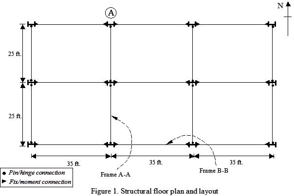
- As shown in Figure 1, the building has two 25-ft. bays in the north-south direction and three 35 ft. bays in the east-west direction.
- There are four structural frames in the north-south direction. These frames have structural elevations similar to frame A-A shown in Figure 2.
- There are three structural frames in the east-west directions. These frames have structural elevations similar to frame B-B shown in Figure 3.
- The building has a roof truss, which is shown in Figures 2 and 3.
- Frame A-A is a braced frame, where all members are connected using pin/hinge connections. Diagonal bracing members are needed for stability.
- Frame B-B is a moment frame, where all members are connected using fix/moment connections. There is no need for diagonal bracing members.
- The north-south and east-west frames resist the vertical gravity loads together.
- The three moment frames in the east-west direction resist the horizontal lateral loads in the east-west direction.
- The four braced frames in the north-south direction resist the horizontal lateral loads in the north-south direction.
1.4 STRUCTURAL MEMBERS
Structural members are categorized based up on the internal forces in them. For example:
- Tension member –subjected to tensile axial force only
- Column or compression member –subjected to compressive axial force only
- Tension/Compression member –subjected to tensile/compressive axial forces
- Beam member –subjected to flexural loads, i.e., shear force and bending moment only. The axial force in a beam member is negligible.
- Beam-column member – member subjected to combined axial force and flexural loads (shear force, and bending moments)
In basic structural analysis (CE371) students have come across two types of structures, namely, trusses and frames. For example, Figure 2 shows a roof truss supported by a braced frame.
- All the members of a truss are connected using pin/hinge connections. All external forces are applied at the pins/hinges. As a result, all truss members are subjected to axial forces (tension or compression) only.
- In braced and moment frames, the horizontal members (beams) are subjected to flexural loads only.
- In braced frames, the vertical members (columns) are subjected to compressive axial forces only.
- In braced frames, the diagonal members (braces) are subjected to tension/compression axial forces only.
- In moment frames, the vertical members (beam-columns) are subjected to combined axial and flexural loads.
For practice, let us categorize the member shown in Figures 2 and 3.

1.5 STRUCTURAL CONNECTIONS
Members of a structural frame are connected together using connections. Prominent connection types include: (1) truss / bracing member connections; (2) simple shear connections; (3) fully-restrained moment connections; and (4) partially-restrained flexible moment connections.
- Truss / bracing member connections are used to connect two or more truss members together. Only the axial forces in the members have to be transferred through the connection for continuity.
- Simple shear connections are the pin connections used to connect beam to column members. Only the shear forces are transferred through the connection for continuity. The bending moments are not transferred through the connection.
- Moment connections are fix connections used to connect beam to column members. Both the shear forces and bending moments are transferred through the connections with very small deformations (full restraint).
- Partially restrained connections are flexible connections used to connect beam to column members. The shear forces are transferred fully through the connection. However, the bending moment is only transferred partially.
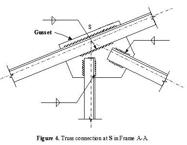
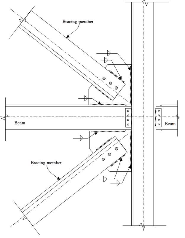
Figure 5. Bracing connection and Simple Shear Connection at G in Frame A-A.
Figure 6. All-bolted double angle shear connection.
Figure 7. Directly welded flange fully restrained moment connection.
- Figure 4 shows an example truss connection. Figure 5 shows an example bracing connection. Figure 6 shows an example shear connection. Figure 7 shows an example moment connection.
- Connections are developed using bolts or welds.
- Bolts are used to connect two or more plate elements that are in the same plane. Bolt-holes are drilled in the plate elements. The threaded bolt shank passes through the holes, and the connection is secured using nuts.
- Bolts are usually made of higher strength steel.
- Welds can be used to connect plate elements that are in the same or different planes. A high voltage electric arc is developed between the two plate elements. The electric arc causes localized melting of the base metal (plate element) and the weld electrode. After cooling, all the molten metal (base and weld) solidifies into one continuum. Thus, developing a welded connection.
- In Figure 4, all the truss members are connected together by welding to a common gusset plate. The axial forces in the members are transferred through the gusset plates. This same connection can also be developed using bolts. How?
- In Figure 5, the bracing members are connected to gusset plates, which are also connected to the beam and column. The bracing member can be connected to the gusset plate using bolts or welds. However, the gusset plate has to be welded to the beam / column.
- In Figure 6, two angles are bolted to the web of the beam. The perpendicular legs of the angles are bolted to the flange of the column. Thus, an all-bolted double-angle shear connection is achieved. This all-bolted connection will be easier to assemble in the field as compared to welding. How is this a shear connection?
- In Figure 7, the beam flanges are beveled and welded directly to the flange of column using full penetration groove welds. This welding will have to be done in the field during erection and it will require the use of back-up bars. Weld-access holes and skilled welders are required to achieve a weld of acceptable quality.
- In Figure 7, the beam web is bolted to a shear tab (plate), which is fillet welded to the column in the shop. This shear tab connection transfers the shear from the beam to the column. How is Figure 7 a moment connection?
1.6 Structural Loads
The building structure must be designed to carry or resist the loads that are applied to it over its design-life. The building structure will be subjected to loads that have been categorized as follows:
- Dead Loads (D): are permanent loads acting on the structure. These include the self-weight of structural and non-structural components. They are usually gravity loads.
- Live Loads (L): are non-permanent loads acting on the structure due to its use and occupancy. The magnitude and location of live loads changes frequently over the design life. Hence, they cannot be estimated with the same accuracy as dead loads.
- Wind Loads (W): are in the form of pressure or suction on the exterior surfaces of the building. They cause horizontal lateral loads (forces) on the structure, which can be critical for tall buildings. Wind loads also cause uplift of light roof systems.
- Snow Loads (S): are vertical gravity loads due to snow, which are subjected to variability due to seasons and drift.
- Roof Live Load (Lr): are live loads on the roof caused during the design life by planters, people, or by workers, equipment, and materials during maintenance.
- Values of structural loads are given in the publication ASCE/SEI 7-10: Minimum Design Loads for Buildings and Other Structures. The first phase of structural design consists of estimating the loads acting on the structure. This is done using the load values and combinations presented in ASCE/SEI 7-10 as explained in the following sub-sections.
1.6.1 Step I. Categorization of Buildings
- Categories I, II, III, and IV. See Table 1.5-1 below and in ASCE/SEI 7-10.
1.6.2 Dead Loads (D)
Dead loads consist of the weight of all materials of construction incorporated into the building including but not limited to walls, floors, roofs, ceilings, stairways, built-in partitions, finishes, cladding and other similarly incorporated architectural and structural items, and fixed service equipment such as plumbing stacks and risers, electrical feeders, and heating, ventilating, and air conditioning systems.
In some cases, the structural dead load can be estimated satisfactorily from simple formulas based in the weights and sizes of similar structures. For example, the average weight of steel framed buildings is 60-75 lb/ft2, and the average weight for reinforced concrete buildings is 110 - 130 lb/ft2.
From an engineering standpoint, once the materials and sizes of the various components of the structure are determined, their weights can be found from tables that list their densities. See Tables 1.2 and 1.3, which are taken from Hibbeler, R.C. (1999), Structural Analysis, 4th Edition.
1.6.3 Live Loads
- Building floors are usually subjected to uniform live loads or concentrated live loads. They have to be designed to safely support the minimum uniformly distributed load or the minimum concentrated live load values given in the ASCE/SEI 7-10 (see Table 4.1 below), whichever produces the maximum load effects in the structural members.
- The minimum uniformly distributed live loads (Lo) given in Table 4.1 above can be reduced for buildings with very large floor areas, because it is unlikely that the prescribed live load will occur simultaneously throughout the entire structure.
- Equation (1.1) can be used to calculate the reduce uniformly distributed live load (L) for members with KLLAT≥400 ft2:
 (1.1)
(1.1)
where, AT is the tributary area in ft2 and KLL is the live load element factor as follows:
KLL is equal to 4.0 for interior columns and exterior columns without cantilever slabs. KLL is equal to 3.0 for edge columns with cantilever slabs.
KLL is equal to 2.0 for corner columns with cantilever slabs, edge beams without cantilever slabs, and interior beams.
KLL is equal to 1.0 for all other members not identified above.
EXCEPTION: Equation 1.1(a) can be used instead of Equation 1.1 for members of one and two-family structures supporting more than one floor load.
 (1.1(a))
Lo1, Lo2 … unreduced floor live load applicable to each of the supported story level irrespective of the tributary area.
L ≥ the largest unreduced floor live load on a given story level acting alone
- Some limitations to the live load reduction are as follows:
L cannot be less than 0.5Lo for members supporting one floor and L cannot be less that 0.4Lo for members supporting two or more floors.
Live loads that exceed 100 lb/ft2 shall not be reduced except the live loads for members supporting two or more floors may be reduced by 20%.
Live loads shall not be reduced for passenger vehicle garages except the live loads for members supporting two or more floors may be reduced by 20%.
Live loads shall not be reduced in assembly uses.
