
Development of the Motor Car Body
Brief History
The first motor car bodies and chassis frames, made between 1896 and 1910, were similar in design to horse-drawn carriages and like the carriages were made almost entirely of wood. The frames were generally made from heavy ash, and the joints were reinforced by wrought iron brackets which were individually fitted. The panels were either cedar or Honduras mahogany about 9.5mm thick, glued, pinned or screwed to the framework. The tops, on cars which had them, were of rubberized canvas or other fabrics. Some bodies were built with closed cabs and the tops were held in place by strips of wood bent to form a solid frame. About 1921 the Weymann construction was introduced, in which the floor structure carried all the weight of the seating and the body shell, which was of very light construction, was attached to the floor unit. Each joint in the shell and between the shell and the floor was made by a pair of steel plates, one on each side of the joint and bolted through both pieces of timber, leaving a slight gap between the two pieces. The panelling was of fabric, first canvas, then a layer of wadding calico and finally a covering of leather cloth. This form of construction allowed flexibility in the framing and made a very light and quiet body frame, but the outer covering had a very short life.
As the demand for vehicles increased it became necessary to find a quicker method of production. Up to that time steel had been shaped by hand, but it was known that metal in large sheets could be shaped using simple die tools in presses and machine presses were introduced to the steel industry to form steel sheets into body panels. Initially the sheets were not formed into complex shapes or contours, and the first bodies were very square and angular with few curves. The frame and inner construction was still for the most part made of wood. In about 1923 the first attempts were made to build all-steel bodies, but these were not satisfactory as the design principles used were similar to those which had been adopted for the timber-framed body.
The real beginning of the all-steel body shell came in 1927, when presses became capable of producing a greater number of panels and in more complex shapes, this was the dawn of the mass production era. During the 1930s most of the large companies who manufactured motor vehicles adopted the use of metal for the complete construction of the body shell and motor cars began to be produced in even greater quantities. Owing to the ever-increasing demand for private transport, competition increased between rival firms, and in consequence their body engineers began to incorporate features which added to the comfort of the driver and passengers. This brought about the development of the closed cars or saloons as we know them today. The gradual development of the shape of the motor car body can be clearly seen in figure 1, which shows a selection of Austin vehicles from 1909 to 1992.
The inner construction of the head roof of these saloons was concealed by a headlining. Up to and including the immediate post-war years, this headlining was made from a woolen fabric stitched together and tacked into position on wooden frames. However, the more recently developed plastic and vinyl materials were found to be more suitable than fabric, being cheaper and easier to clean and fit. They are fitted by stretching over self-tensioning frames which are clipped into position for easy removal, or alternatively the headlining is fastened into position with adhesives.
Comfort improved tremendously with the use of latex foam rubber together with coil springs in the seating, instead of the original plain springing. The general interior finish has also been improved by the introduction of door trim pads, fully trimmed dash panels and a floor covering of either removable rubber or carpeting.
Then came the general use of celluloid for windows instead of side curtains and next a raising and lowering mechanism for the windows, nowadays the windscreen and door glasses are made of laminated and/or toughened safety glass. The window mechanism in use today did not begin to develop until well into the 1920s.
Mudguards, which began as wooden or leather protections against splattered mud, grew into wide splayed deflectors in the early part of the twentieth century and then gradually receded into the body work, becoming gracefully moulded into the streamlining of the modern motor car and taking the name of wings. Carriage steps retained on earlier models gave place to running boards which in turn disappeared altogether.
Steering between 1890 and 1906 was operated by a tiller. This was followed by the steering wheel which is in current use. The position of the gear lever made an early change from the floor to the steering column, only to return to some convenient place on the floor.
Some of the first vehicles, or horseless carriages as they were known, carried no lights at all; then carriage candle lamps, acetylene lamps and finally the electric lighting system, first fitted as a luxury extra and ultimately becoming standard and finally obligatory equipment which must conform with legislation of the day.
When windscreens were first introduced such accessories as windscreen wipers and washers were unknown. Then came the single hand operated wiper, followed by the suction wiper and finally electrically driven wipers.
The design of the wheels was at first dictated by fashion. It was considered necessary for the rear wheels to be larger than the front, a legacy from the elegant horse drawn carriages. Wooden spokes and iron tyres were the first wheels to appear and with both rear and front wheels of the same dimensions. Then came the wooden-spoked artillery wheel with pneumatic tyre. The artillery wheel gave way to the wire-spoked wheel, and this in turn to the modern disc wheel with tubeless tyres.
Great strides have been made in the evolution of the motor car since 1770, when Cugnot’s steam wagon travelled at 3 mile/h (4.8km/h), to the modern vehicle which can carry driver and passengers in silence, comfort and safety at speeds which at one time were thought to be beyond human endurance: indeed, special vehicles on prepared tracks are now approaching the speed of sound.
It must be borne in mind that the speed of the vehicle is governed by (a) the type of power unit, (b) its stability and maneuvering capabilities and (c) its shape, which is perhaps at present one of the most important features in high-speed travel. Whatever the mechanical future of the car, we may rest assured that the shape of the motor car body will continue to change as technical progress is made.
1.1 Highlights of Motor Vehicle History
The idea of a self-propelled vehicle occurs in Homer’s Ilad. Vulcan, the blacksmith of the gods, in one day made 20 tricycles with ‘self-moved obedient to the beck of the gods’. The landmarks in more modern motor vehicle history are as follows:
1688 |
Ferdinand Verbiest, missionary in China, made a model steam carriage using the steam turbine principle. |
1740 |
Jacques de Vaucansen showed a clockwork carriage in Paris. |
1765 |
Watt developed the steam engine |
1765 |
Nicholas Joseph Cugnot, a French artillery officer, built a steam wagon which carried four people at a speed of 2.25 mile/h. It overturned in the street of Paris and Cugnot was thrown into prison for endangering the populace. |
1803 |
Richard Trevithickbuilt a steam carriage and drove it in Cornwall. |
1831 |
Sir Charles Dance ran a steam coach (built by Sir Goldsworthy Gurney) on a regular service from Gloucester to Cheltenham. Sometimes they did four round trips a day, doing 9 miles in 45 minutes. The steam coaches were driven off the road by the vested interests of the stage coach companies, who increased toll charges and piled heaps of stones in the roads along which the steam coaches passed. This, combined with mechanical breakdowns and the advent of railways, contributed to the withdrawal of the steam coaches. |
1859 |
Oil was discovered in USA. |
1865 |
The Locomotive Act of 1865 (The Red Flag Act) was pushed through by the railway and coach owners. One of the stipulations was that at least three people must be employed to conduct the locomotive through the streets, one of whom had to walk 60 yards in front carrying a red flag. Speeds were restricted to 2-4 miles/h. this legistration held back the development of the motor vehicle in Great Britain for 31 years, allowing the continentral countries to take the lead in this field. |
1885 |
Karl Benz produced his first car. This is recognized as being the first car with an internal combustion engine as we know it. |
1886 |
Gottlieb Daimler also produced a car. |
1890 |
Panhard and Levasser began making cars in France. |
1892 |
Charles and Frank Duryea built the first American petrol-driven car, although steam cars had been in use long before. |
1895 |
First motor race in Paris. First Automobile Club formed in Paris. |
1896 |
The repeal of the Red Flag Act. This is commemorated by the London to Brighton veteran car run. The speed limit was raised to 12 mile/h and remained at that until 1903, when the 20 mile/h limit in built-up areas was introduced. There was much persecution of motorists by police at this time, which led to the formation of the RAC and AA. |
1897 |
The RAC was formed, largely through the efforts of F.R.Simms, who also founded the SMMT in 1902. |
1899 |
Jenatzy set world speed record of 66 mile/h. |
1900 |
Steering wheel replaces tiller. Frederick Lanchester produced his first car, a 10 hp model. He had built an experimental phaeton in 1895. |
1901 |
Front-mounted engine. Mercedes car produced. |
1902 |
Running board. Serpollet did a speed of 74 km/h in a steam car. |
1903 |
Pressed steel frames. First windshield. The Motor Car Act resulted in considerable persecution of the motorist for speeding number plates and lights, so much so motoring organizations paid cyclists to find police speed traps. |
1904 |
Folding windshield. Closed saloon-type body. A petrol car reached 100 mile/h and in the same year a Stanley steam car achieved a speed of 127 mile/h. Stanley steam cars used paraffin in a multitube boiler and had a chassis made from hickory. Rolls Royce exhibited their first car in Paris. The motoring press were impressed with its reliability. Veteran cars are cars up to and including this year. |
1.2 Terms used to Describe Early Vehicle Body Styles
In the history of the motor car there has been some ambiguity in the names used to describe various types of body styles, built by coach builders from different countries. The following terms relate to the vehicles produced during the period 1895 to 1915 and show the derivation of the terminology used to describe the modern vehicle:
Berlina: Rarely used before the First World War. A closed luxury car with small windows which allowed the occupants to see without being seen.
Cab: A term taken directly from the days of horse-drawn carriages. Used to describe an enclosed vehicle which carried two passengers, while the driver was situated in front of this compartment and unprotected.
Cabriolet: Used towards the end of the period, describes a car with a collapsible hood and seating two or four people.
Coupé: A vehicle divided by a fixed or movable glass partition, behind the front seat. The driver’s position was only partially protected by the roof whilst the rear compartment was totally enclosed and very luxurious.
Coupé Cabriolet or Double Cabriolet: A long vehicle having the front part designed as a coupe and the rear part designed as a cabriolet. There were often two supplementary seats.
Coupé de Ville: A coupé having the driving position completely open.
Coupé Limousine: A vehicle having a totally enclosed rear compartment and the front driving position closed on the sides only.
Double Berlina: A longer version of the Berlina but having the driving position separated from the rear part of the vehicle.
Double Landaulet: A longer version of the landaulet. It had two permanent seats plus two occasional seats in the rear and a driving position in front.
Double Phaeton: A phaeton which had two double seats including the driver’s seat.
Double Tunneau: A longer version of the tonneau in which the front seats were completely separated from the rear seats.
Landau: A cariolet limousine having only the roof behind the rear windows collapsible.
Landaulet or Landaulette: A small landau having only two seats in the closed collapsible roof portion.
Limousine: A longer version of the coupe with double side windows in the rear compartment.
Limousine Chauffeur: A limousine with an extended rear roof to cover the driving position.
Phaeton: A term from the days of the horse-drawn carriage. In early motoring it was used to describe a lightweight car with large spoked wheels, one double seat and usually a hood.
Runabout: An open sporting type of vehicle with simple bodywork and two seats only.
Tonneau: An open vehicle having a front bench seat and a semicircular rear seat which was built into the rear doors.
Glass Saloon: A large closed vehicle similar to a double Berlina but with enlarged windows.
Saloon: A vehicle having the driving seat inside the enclosed car but not separated from the rear seat by a partition.
Torpedo: A long sports vehicle having its hood attached to the windscreen.
Victoria: Another term derived from the era of horses. The Victoria was a long, luxurious vehicle with a separate driving position and a large rear seat. It was equipped with hoods and side screens.
Wagon Saloon: A particularly luxurious saloon used for official purposes.
1.3 Vehicle Classification:
There are many ways in which motor vehicles may be classified into convenient groups for recognition. Much depends on such factors as the manufacturer, the make of the car, the series and the body type or style. Distinctive groups of passenger vehicle bodies include the following:
Styling forms include the following:
Saloon: The most popular style for passenger vehicles is the two -door or four-door saloon. It has a fully enclosed, fixed-roof body for four or more people. This body style also has a separate luggage or boot compartment.
Hatchback: This body style is identified by its characteristic sloping rear tailgate, which is classed as one of the three or five doors. With the rear doors down there is no division between the passenger and luggage compartments and this increases the luggage carrying capacity of the vehicle.
Estate: This type of vehicle is styled so that roof extends to the rear to give more luggage space, especially when the rear seats are lowered.
Sports coupé and coupé: A sports coupe is a two seated sports car with a fixed roof and a high-performance engine. A coupé is a two-door, fixed-roof, high performance vehicle with similar styling but with two extra seats at the rear and is sometimes referred to as a 2-plus-2.
Convertible or Cabriolet: This can have either two or four doors. It has a soft-top folding roof (hood) and wind-up windows, together with fully enclosed or open bodywork.
Sports: This is a two-seater vehicle with a high-performance engine and a folding or removable roof (hood).
Limousine: This vehicle is characterized by its extended length, a high roofline to allow better headroom for seating five passengers comfortably behind the driver, a high-quality finish and luxurious interiors.
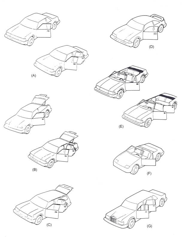 Figure 4: Vehicle Styling Forms
(A) Saloon (B) Hatchback (C) Estate (D) Coupé (E) Convertible (F) Sports (G) Limousine
1.4 The Evolution of Design
When the first motor cars appeared, little attention was paid to their appearance, it was enough that they ran. Consequently the cars initially sold to the public mostly resembled horse-drawn carriages with engines added. Henry Ford launched his Model T in 1908, and it sold on its low price and utility rather than its looks. However, the body design of this car had to be changed over its 19 year production span to reflect changes in customer taste.
The 1930s saw greater emphasis on streamlining design. Manufacturers began to use wind tunnels to eliminate unnecessary drag-inducing projections from their cars. One of the dominant styling features of the 1950s and 1960s was the tail fin, inspired by the twin tail fins of the wartime Lockhead Lightning fighter aircraft. Eventually a reaction set in against such excesses and the trend returned to more streamlined styling.
In creating cars for today’s highly competitive car market, designers have to do far more than just achieve a pleasing shape. National legal requirements determine the positions of lamps direction indicators and other safety-related items, while the buying market has become much more sophisticated than before. Fuel economy, comfort, function and versatility are now extremely important.
1.5 Creation of a New Design from Concept to Realization
The planning, design, engineering and development of a new motor car is an extremely complex process. With approximately 15,000 separate parts, the car is the most complicated piece of equipment built using mass production methods. Every major design project has its own design team led by a design manager and they stay with the project throughout. The size of the team varies according to the progress and status of the project. The skill and judgment of the trained and experienced automotive designer is vital to the creation of any design concept.
To assist in the speed and accuracy of the ensuring stages of the design process (the implementation), some of the most advanced computer-assisted design equipment is used by the large vehicle manufacturers. For example, computer-controlled measuring bridges that can automatically scan model surfaces, or machines that can mill surfaces, are linked to a computer centre through a highly sophisticated satellite communication network. The key terms in computer equipment are as follows:
Computer-aided Design (CAD): Computer assisted design work, basically using graphics.
Computer-aided Engineering (CAE): All computer aided activities with respect to technical data processing, from idea to preparation for production, integrated in an optimum way.
Computer-aided Manufacturing (CAM): Preparation of production and analysis of production processes.
Computer-integrated manufacturing (CIM): All computer-aided activities from idea to serial production.
The use of CAE is growing in the automotive industry and will probably result in further widespread changes. Historically, the aerospace industry was the leader in CAE development. The three major motor companies of GM, Ford and Chrysler started their CAE activities as soon as computers became readily available in the early 1960s. the larger automotive companies in Europe started CAE activities in the early 1970s – about the same time as the Japanese companies.
Each new project starts with a series of detailed paper studies, aimed at identifying the most competitive and innovative product in whichever part of the market is under review. Original research into systems and concepts is then balanced against careful analysis of operating characteristics, features performance and economy targets, the projected cost of ownership and essential dimensional requirements. Research into competitors’ vehicles, market research to judge tastes in future years, and possible changes in legislation are all factors that have to be taken into account by the product planners when determining the specification of a new vehicle.
The various stages of the design process are as follows:
1.6 Vehicle Styling
Styling
Styling has existed from the early times. However, the terms ‘stylist’ and ‘styling’ originally came into common usage in the automotive industry during the first part of the twentieth century.
The automotive stylist needs to be a combination of artist, inventor, craftsman and engineer, with the ability to conceive new and imaginative ideas and to bring these ideas to economic reality by using up-to-date techniques and facilities. He must have a complete understanding of the vehicle and its functions, knowledge of materials available, the costs involved, the capabilities of the production machinery, the sources of supply and the directions of worldwide changes. His responsibilities include the conception, detail, design and development of all new products, both visual and mechanical. This includes the exterior form, all applied facias, the complete interior, controls, instrumentation, seating and the colours and textures of everything visible outside and inside the vehicle.
Styling departments vary enormously in size and facilities, ranging from the individual consultant stylist to the comprehensive resources of major American motor corporations like General Motors, who have more than 2000 staff in their styling department at Detroit. The individual consultant designer usually provides designs for organizations which are too small to employ fulltime stylists. Some act as an additional brain for organizations who want to inject new ideas into their own production. Among the famous designers are the Italians Pininfarina (Lancia, Ferrari, Alfa), Bertone (Lamborghini), Ghia (ford) and Issigonis (mini).
The work of the modern car stylist is governed by the compromise between his creativity and the world of production engineering. Every specification, vehicle type, payload, overall dimensions, engine power and vehicle image inspire the stylist and the design proposals he will make. Initially he makes freehand sketches of all the fundamental components placed in their correct positions. If the drawing does not reduce the potential of the original ideas, he then produces more comprehensive sketches of this design, using colours to indicate more clearly to the senior executives the initial thinking of the design. Usually the highly successful classic designs are the work of one outstanding individual stylist rather than of a team.
The main aim of the designer is to improve passenger comfort and protection, vision, heating and ventilation. The styling team may consider the transverse engine as a means of reducing the space occupied by the mechanical elements of the car. Front-wheel drive eliminates the driveshaft and the tunnel and the occupants can sit more comfortably. Certain minimum standards are laid down with regard to seat widths, knee-room and headroom. The interior dimensions of the car are part of the initial specifications and not subject to much modification. Every inch of space is considered in the attempt to provide the maximum interior capacity for the design. The final dimensions of the interior and luggage space are shown in a drawing, together with provision for the engine and remaining mechanical assemblies.
Ergonomics
Ergonomics is a fundamental component of the process of vehicle design. It is the consideration of human factors in the efficient layout of controls in the driver’s environment. In the design of instrument panels, factors such as the driver’s reach zones and his field of vision together with international standards, all have to be considered. Legal standards include material performance in relation to energy absorption and deformation under impact. The vision and reach zones are geometrically defined, and allow for the elimination of instrument reflections in the windshield. Basic elements affecting the driver’s relationship to the instrument panel controls, instruments, steering wheel, pedals, seats and other vital elements in the car are positioned for initial evaluation using the ‘Manikin’, which is a two and three dimensional measuring tool developed as a result of numerous anthropometric surveys and representing the human figure. Changes are recorded until the designer is satisfied that an optimum layout has been achieved.
1.7 Safety
With regards to bodywork, the vehicle designer must take into account the safety of the driver, passengers and other road users. Although the vehicle cannot be expected to withstand collision with obstacles or other vehicles, much can be done to reduce the effects of collision by the use of careful design of overall shape, the selection of suitable materials and the design of the components, the chances of injury can be reduced both outside and inside the vehicle by avoiding sharp-edged, projecting elements.
Every car should be designed with the following crash safety principles in mind:
Safety-related vehicle laws cover design, performance levels and the associated testing procedures: requirements for test inspections, documentation and records for the process of approval: checks that standards are being maintained during production; the issue of safety-related documentation and many other requirements throughout the vehicle’s service life.
Primary or active safety
This refers to the features designed into the vehicle which reduce the possibility of an accident. These include primary design elements such as dual-circuit braking systems, anti-lock braking systems high aerodynamic stability and efficient bad weather equipment, together with features that make the driver’s environment safer, such as efficient through ventilation, orthopaedic seating, improved all-round vision, easy to read instruments and ergonomic controls.
An anti-lock braking system (ABS) enhances a driver’s ability to steer the vehicle during hard braking. Sensors monitor how fast the wheels are rotating and feed data continuously to a microprocessor in the vehicle to signal that a wheel is approaching lockup. The computer responds by sending a signal to apply and release brake pressure as required. This pumping action continues as long as the driver maintains adequate force on the brake pedal and impending wheel condition is sensed.
The stability and handling of the vehicle are affected by the width of the track and the more stable is the vehicle.
Secondary or passive safety
If a crash does happen, secondary safety design should protect the passengers by:
The primary concern is to develop efficient restraint systems which are comfortable to wear and easy to use. Manufacturers are now fitting automatic seatbelt tensioners. These automatic ‘body lock’ front seatbelt tensioners reduce the severity of head injuries by 20 per cent with similar gains in chest protection. In impacts over 12 mile/h (20 km/h) the extra tension in the seatbelts buckle triggers a sensor which tightens the lap and diagonal belts in 22 milliseconds, that is before the occupant even starts to move. In addition, because it operates at low speeds, it covers a broad spectrum of accident situations. Anti-submarining ramps built into the front seats further aid safety by reducing the possibility of occupants sliding under the belt.
There are also engineering features such as impact energy-absorbing steering columns, head restraints, bumpers, anti-burst door locks and self aligning steering wheels. Anti-burst door locks are to prevent unrestrained occupants from falling out of the vehicle, especially during roll over. The chances of survival are much reduced if the occupant is thrown out. Broad padded steering wheels are used to prevent head or chest damage. Collapsible steering columns also prevent damage to the chest and abdomen and are designed to prevent the steering column being pushed back into the passenger compartment whilst the front end is crumpling. The self-aligning steering wheel is designed to distribute force more evenly if the driver comes into contact with the steering wheel during a crash. This steering wheel has an energy absorbing hub which incorporates six deformable metal legs. In a crash, the wheel deforms at the hub and the metal legs align the wheel parallel to the chest of the driver to help spread the impact and reduce chest, abdomen and facial injuries.
Body shells are now designed to withstand major collision and rollover impacts while adsorbing shock by controlled deformation of structure in the front and rear of the vehicle. Vehicle design and accident prevention is based on the kinetic energy relationship of damage to a vehicle during collision. Energy is absorbed by work done on the vehicle materials such as foam-filled plastics and heavy rubber sections. Data indicates the long energy-absorbing distances should be provided in vehicle design and the panel assemblies used for this purpose should have a lower stiffness than the central section or passenger compartment of the vehicle.
1.10 The Development and Construction of the Car Body
Using wood and clay allows for modifications to be made easily. At the same time, design engineering personnel construct models of alternative interiors so that locations of instruments can be determined.
A ¼ or ⅜ scale model is produced from the stylist’s drawings to enable the stylist designer to evaluate the three-dimensional aspect of the vehicle. These scale models can look convincingly real. The clay surfaces are covered with thin coloured plastic sheet which closely resembles genuine painted metal. Bumpers, door, handles and trim strips are all cleverly made-up dummies, and the windows are made of Plexiglass. The scale models are examined critically and tested. Changes to the design can be made at this stage.
Full-size Models
A full-size clay model is begun when the scale model has been satisfactorily modified. It is constructed in a similar way to the scale model but uses a metal, wood and plastic frame called a buck. The clay is placed on to the framework by professional model makers, who create the final outside shape of the body to an accuracy of 0.375mm. The high standard of finish and detail results in an exact replica of the future full-size vehicle.
This replica is then evaluated by the styling management and submitted to top management for their approval. The accurate life-size model is used for further wind tunnel testing and also to provide measurements for the engineering and production departments. A scanner, linked to a computer, passes over the entire body and records each and every dimension. These are stored and can be produced on an automatic drafting machine.
The same dimensions can also be projected on the screen of a graphic station; this is a sophisticated computer-controlled video system showing three-dimensional illustrations, allowing design engineers either to smooth the lines or to make detail alterations. The use of computer or CAD allows more flexibility and saves a lot of time compared with more conventional drafting systems.
At the same time as the exterior model is being made, the interior model is also being produced accurately in every detail. It shows the seating arrangement, instrumentation, steering wheel, control unit location and pedal arrangements. Colours and fabrics are tired out on this mock-up until the interior styling is complete and ready for approval.
Engineering Performance and Testing
Development engineers prepare to test an engine in a computer-linked test cell to establish the optimum settings for the best performance, economy and emission levels. With the increasing emphasis on performance with economy, computers are used to obtain the best possible compromise. They are also used to monitor and control prolonged engine testing to establish reliability characteristics. If current engines and transmissions are to be used for a new model, a programme of refining and adapting for the new installation has to be initiated. However, if a completely new engine, transmission or driveline configuration is to be adopted, development work must be well in hand by this time.
Aerodynamics and Wind Tunnel Testing
Aerodynamics is an experimental science whose aim is the study of the relative motions of a solid body and the surrounding air. Its application to the design of a car body constitutes one of the chief lines of the search for energy economy in motor vehicles.
In order to move over flat ground, a car must overcome two forces:
1. Resistance to type tread motion, which varies with the coefficient of tyre friction over the ground and with the vehicle’s mass.
2. Aerodynamic resistance, which depends on the shape of the car, on its frontal area, on the density of the air and on the square of the speed.
One of the objects of aerodynamics research is to reduce the latter: in other words to design a shape that will, for identical performance, require lower energy production. An aerodynamic or streamlined body allows faster running for the same consumption of energy, or lower consumption for the same speed. Research for the ideal shape is done on reduced scale models of the vehicle. The models are placed in a wind tunnel, an experimental installation producing wind of a certain quality and fitted with means for measuring the various forces due to the action of the wind on the model or vehicle. Moreover, at a given cruising speed, the more streamlined vehicle has more power left available for acceleration: this is a safety factor.
The design of a motor car body must, however, remain compatible with imperatives of production, of overall measurements and of inside spaciousness. It is also a matter of style, for the coachwork must be attractive to the public. This makes it impossible to apply the laws of aerodynamics literally. The evolution of the motor car nevertheless tends towards a gradual reduction in aerodynamic resistance.
Aerodynamic Drag
The force which opposes the forward movement of an automobile is aerodynamic drag, in which air rubs against the exterior vehicle surfaces and forms disturbances about the body, thereby retarding forward movement.
Aerodynamic drag increases with speed; thus if the speed of a vehicle is doubled, the corresponding engine power must be increased by eight times. Engineers express the magnitude of aerodynamic drag using the drag coefficient Cd. The coefficient expresses the aerodynamic efficiency of the vehicle: the smaller the value of the coefficient, the smaller the aerodynamic drag.
Figure 15 illustrates the improvements in aerodynamic drag coefficient achieved by alterations to the shape of vehicles. Over the years, the value Cd has been reduced roughly as follows:
1910 0.95 1960 0.40 1920 0.82 1970 0.36 1930 0.56 1980 0.30 1940 0.45 1990 0.22 1950 0.42 1993 0.20 (probable)
Figure 15 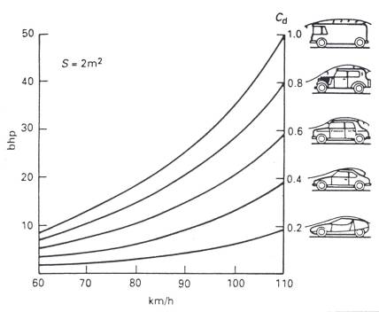 : Theoretical Drag Curves
Theoretical drag curves for four types of vehicle, all reduced for comparison purposes to a …… section of 2m². Since air resistance increases in proportion to the square of the speed, a truck with Cd 1.0 requires 35 bhp at 100km/h, whereas a coupé with Cd 0.2 requires only 7bhp.
During the wind tunnel test all four wheels of the car rest on floating scales connected to a floor balance, which has a concrete foundation below the main floor area. The vehicle is then subjected to an air stream of up to 112 mile/h: the sensitive balances register the effect of the headwind on the vehicles as it is either pressed down or lifted up from the floor, pushed to the left or right, or rotated about its longitudinal axis. The manner in which the forces affect the vehicle body and the location at which the forces are exerted depends upon the body shape, underbody contours and projecting parts. The fewer disturbances which occur as air moves past the vehicle, the lower its drag. Threads on the vehicle exterior as well as smoke streams indicate the air flow and enable test engineers to see where disturbance exists and where air flows are interrupted or redirected and therefore where reshaping of the body is necessary in order to produce better aerodynamics.
Prototype Production
The new model now enters the prototype phase. The mock-ups give way to the first genuine road-going vehicle, produced with the aid of accurate drawings and without complex tooling and machinery. The prototype must accurately reproduce the exact shape, construction and assembly conditions of the final production body it represents if it is to be of any value in illustrating possible manufacturing problems and accurate test data. The process begins with the issue of drawing office instructions to the experimental prototype workshop. Details of skin panels and other large pressings are provided in the form of tracings as photographic reproductions of the master body drafts. As the various detailed parts are made by either simple press tools or traditional hand methods, they are spot welded into minor assemblies or subassemblies; these later become part of a major assembly to form the complete vehicle body.
Prototype Testing
Whilst still in the prototype stage, the new car has to face a number of arduous tests. For these tests a mobile laboratory is connected to the vehicle by a cable, which transmits signals from various sensors on the vehicle back to the onboard computer for collation and analysis. The prototype will also be placed on a computer-linked simulated rig to monitor, through controlled vibrations, the stresses and strains experienced by the driveline, suspension and body. Crash testing is undertaken to establish that the vehicle will suffer the minimum of damage or distortion in the event of an impact and that the occupants are safely installed within the strong passenger compartment or safety cell. The basic crash test is a frontal crash at 30 mile/h (48 km/h) into a fixed barrier set perpendicularly to the car’s longitudinal axis. The collision is termed 100 per cent overlap, as the complete front of the car strikes the barrier and there is no offset. The main requirement is that the steering wheel must not be moved back by more than 120mm (5in), but there is no requirement to measure the force to which the occupants will be subject in collision. The manufacturers use anthropometric dummies suitably instrumented with deceleration and strain gauges which collect relevant data on the effect of the collision on the dummies. A passenger car side impact test aimed at reducing chest and pelvic injuries have been legal in the USA since 1993. This stricter standard requires that a new vehicle must pass a full-scale crash test designed to simulate a collision at an intersection in which a car traveling at 15 mile/h is hit in the side by another car traveling at 30 mile/h. this teat is called an angled side-swipe: the displacement is 27 degrees forward from the perpendicular of the test vehicle’s main axis. The test is conducted by propelling a movable deformable barrier at 33.5 mile/h into the side of the test car occupied by dummies in the front and rear seats. The dummies are wired with instruments to predict the risk potential of human injury.
Figure 16: Wind Tunnel Testing of a Prototype
Source: http://local.ecollege.ie/Content/APPRENTICE/liu/vbr_notes/module3/m3u4.doc
Web site to visit: http://local.ecollege.ie/
Author of the text: indicated on the source document of the above text
If you are the author of the text above and you not agree to share your knowledge for teaching, research, scholarship (for fair use as indicated in the United States copyrigh low) please send us an e-mail and we will remove your text quickly. Fair use is a limitation and exception to the exclusive right granted by copyright law to the author of a creative work. In United States copyright law, fair use is a doctrine that permits limited use of copyrighted material without acquiring permission from the rights holders. Examples of fair use include commentary, search engines, criticism, news reporting, research, teaching, library archiving and scholarship. It provides for the legal, unlicensed citation or incorporation of copyrighted material in another author's work under a four-factor balancing test. (source: http://en.wikipedia.org/wiki/Fair_use)
The information of medicine and health contained in the site are of a general nature and purpose which is purely informative and for this reason may not replace in any case, the council of a doctor or a qualified entity legally to the profession.
The texts are the property of their respective authors and we thank them for giving us the opportunity to share for free to students, teachers and users of the Web their texts will used only for illustrative educational and scientific purposes only.
All the information in our site are given for nonprofit educational purposes