Generally, industrial draughtsmen do not complete one view on a drawing before starting the next, but rather work on all views together. While projecting features between views, a certain amount of mental checking takes place regarding shape and form, and this assists accuracy. The following series of drawings shows stages in producing a typical working drawing in first angle projection.
Stage 1 (Figure 1). Estimate the space required for each of the views from the overall dimensions in each plane, and position the views on the available drawing sheet so that the spaces between the three drawings are roughly the same.
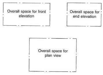
Figure 1 - Stage 1
Stage 2 (Figure 2). In each view, mark out the main centre-lines. Position any complete circles, in any view, and line them in from the start, if possible. Here complete circles exist only in the plan view. The heights of the cylindrical features are now measured in the front view and are projected over to the end view.
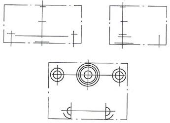
Figure 2 - Stage 2
Stage 3 (Figure 3). Complete the plan view and project up into the front view the sides of the cylindrical parts.
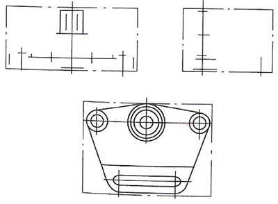
Figure 3 - Stage 3
Stage 4 (Figure 4). Complete the front and end views. Add dimensions, and check that the drawing (mental check) can be redrawn from the dimensions given; otherwise the dimensioning is incomplete. Add the title and any necessary notes.
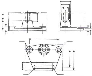
Figure 4 - Stage 4
It is generally advisable to mark out the same feature in as many views as is possible at the same time. Not only is this practice time-saving, but a continuous check on the correct projection between each view is possible, as the draughtsman then tends naturally to think in the three dimensions of length, breadth and depth. It is rarely advantageous to complete one view before starting the others.
Figure 5 - Scale Drawing 1
Figure 6 - Scale Drawing 2
Figure 7 - Scale Drawing 3
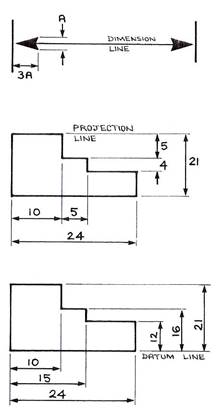
Arrowheads
Dimension lines usually end in an arrowhead. This should be dark and of the proportions shown
Projection lines
Start with a short gap. The smaller dimensions are shown nearest the drawing and the larger dimensions farther out.
Datum lines
In order to avoid slight inaccuracies accumulating, dimensions are often all taken from a single reference or datum line.
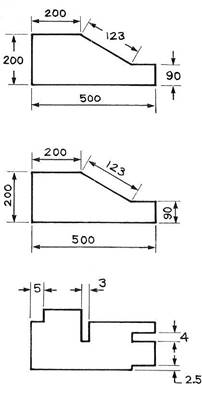
The unidirectional system
This is the preferred method. All the dimensions are written to be read from one position only, as shown.
The aligned system
Here the dimensions are written along and parallel to the dimension lines.
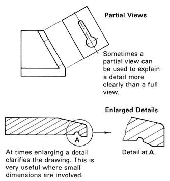
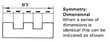
Dimensioning of small linear features
Avoid situations where the numeral appears to be an extension of a projection or dimension line.
Note: Each industry has evolved its own abbreviations and conventions. Many of these are set out in BS 308.
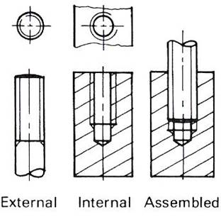
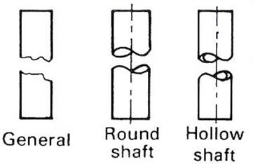
Table 1 - Abbreviations in Common use on Orthographic Drawings
Convention |
Representation |
Screw Threads |
|
Interrupted Views |
|
 An orthographic projection is used to show views of individual faces. The number of views required depends upon the details of the component. This method is the most commonly used for production engineering, as it is often the only way to give the detailed information required to enable components to be manufactured correctly, direct from the drawings. These drawings may take a long time to prepare and there are times when sufficient information can be given on one drawing, especially for very simple details.
For this purpose, we can use isometric or oblique projections, but the main purpose of these two projections is to provide a pictorial drawing of an object, which will convey shape and comparative size, rather than detailed dimensions.
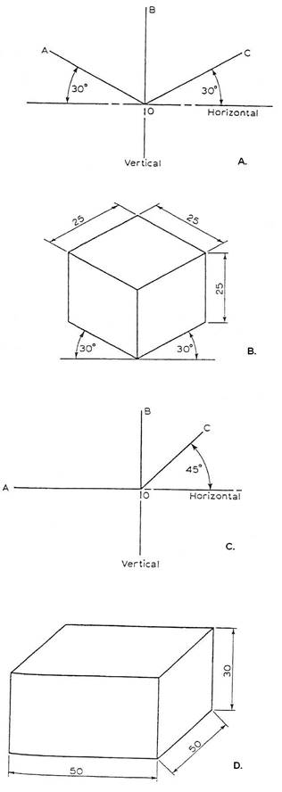
An isometric projection shows both sides of an object to equal advantage (B), whereas an oblique projection gives prominence to the side shown at the front (D).
When constructing an isometric projection, the three axes are positioned as at A and all lines represent actual dimensions.
When constructing an oblique projection, the axes are as at C. All vertical and horizontal lines are drawn to represent the actual dimensions, but the dimensions represented by the lines parallel to O-C are drawn to the ratio 1:2, i.e. a 25 mm line represents a 50 mm dimension (see D).
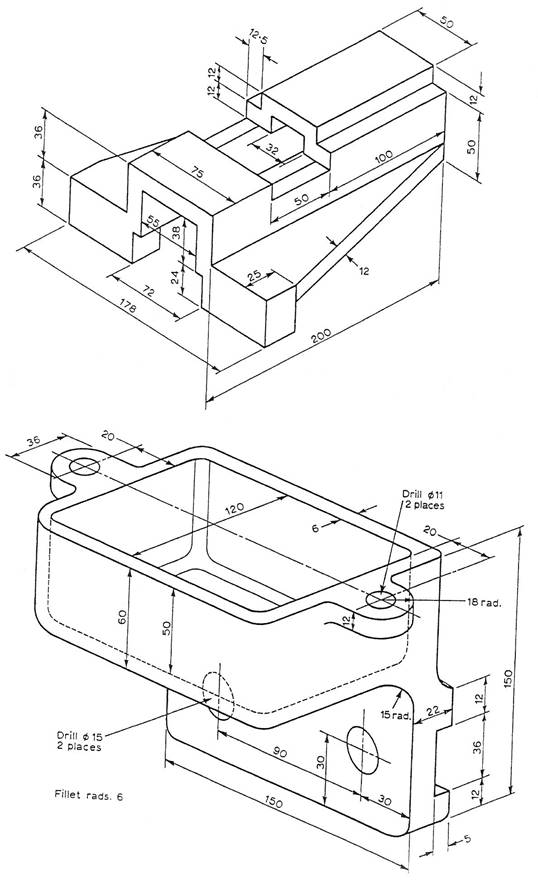
Figure 8 - Isometric and Oblique Drawings
Fig. A shows a pictorial view of a vee block and Fig. B shows two views of the same block drawn in third angle projection. Fig. C shows three views of the dovetail block shown at Fig. D. In this case, three views are necessary to show all the detail.
From the pictorial views shown on the following three pages, draw the necessary views in third angle projection.
The following notes and illustrations are intended to assist in reading and understanding simple drawings. In all orthographic drawings, it is necessary to project at least two views of a three dimensional object - or one view and an adequate description in some simple cases, a typical example being the drawing of a ball for a bearing. A drawing of a circle on its own could be interpreted as the end elevation of a cylinder or a sphere. A drawing of a rectangle could be understood as part of a bar of rectangular cross-section, or it might be the front elevation of a cylinder. It is therefore generally necessary to produce at least two views, and these must be read together for a complete understanding. Figure 9 shows various examples where the plan views are identical and the elevations are all different.
Figure 9 - Identical Plan Views and Differing Elevations
A single line may represent an edge or the change in direction of a surface, and which it is will be determined only by reading both views simultaneously.
A certain amount of imagination is therefore required when interpreting engineering drawings. Obviously, with an object of greater complexity, the reading of three views, or more, may well be necessary.
Press brakes are designed to bend to a rated CAPACITY based on a 'die ratio' of 8:1 which is accepted as ideal conditions. Figure 10 shows the meaning of Die ratio. This is recommended for use with a standard 'Vee' die for 90° 'air bends', and gives an INSIDE RADIUS approximately equal to the THICKNESS of the metal.
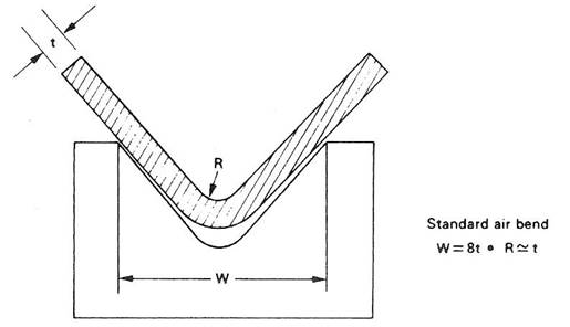
Figure 10 - Die Ratio
Different thicknesses of plate formed over the same die will have the same inside radius, but the force or load required for bending will vary considerably.
If the die opening is less than 8 times the metal thickness, fracturing on the outside of the bend may occur. However, it is possible to produce satisfactory bends in light gauge sheet metal using a die opening of 6 times the metal thickness, but this requires a greater pressure.
For 'HIGH TENSILE' plates and plates above 9.525 mm thickness, it is recommended that the die opening be increased to 10 to 12 times the metal thickness. This considerably reduces the bending load required.
The pressure required for bending is in direct relation to the tensile strength of the material. For materials other than MILD STEEL the capacity would have to be DECREASED or INCREASED accordingly. A long machine will bend plates thicker than the rated capacity but only over shorter lengths than the rated capacity, providing the plates are appreciably shorter than the maximum tool or die length.
Thinner plates than the rated capacity can usually be bent over the full length of the dies but the MAXIMUM WIDTH OF FLANGE IS DETERMINED BY THE DEPTH OF GAP. A standard bend has an inside radius approximately equal to the thickness of the metal. If this radius is not important and a slightly larger radius would be quite satisfactory then, in many cases, a larger die opening could be employed and the machine will be able to bend plates thicker than the rated capacity over the rated length.
Figure 11 - Versatility of Pressure Bending
Interchangeable four-way dies - Figure 11(a). The interchangeable female dies are used for bending medium and heavy plate. They are provided with 85° openings on each of the four faces.
Male punches for use with four-way dies are usually made with a 60° angle.
Acute angle dies - Figure 11(b). Acute angle dies have many uses and, if used in conjunction with flattening dies, a variety of seams and hems may be produced on sheet metal.
These tools are available for any angle, but if the female die is less than 35° the sheet tends to stick to the die.
Acute angle dies may be set to bend 90° by adjusting the height of the ram.
The Goose-neck punch - Figure 11(c). When making a number of bends on the same component, clearance for previous bends has to be considered. Goose-neck punches are specially designed for the above purpose. These tools are very versatile, enabling a variety of sheet-metal sections to be formed.
The bending force for MILD STEEL is given in Table 2, whilst the bending force for other materials is given in Table 3.
Flattening (planishing) tools - Figure 11(d). Flattening tools of various forms may either be used in pairs for flattening a returned edge, or hem, on the edge of sheet metal or in conjunction with a formed male or female die (as illustrated for closing a countersunk grooved seam in sheet-metal work).
Radius bending - Figure 11(e). A radius bend is best formed in a pair of suitable tools. The radius on the male punch is usually slightly less than that required allowing for 'springback' in the material. A large radius can be produced by simply adjusting the height of the ram and progressively feeding the sheet through the tools.
Channel dies - Figure 11(f). Channel dies are made with 'pressure pads' so that the metal is held against the face of the male die during the forming operations. As a general rule, channel dies are only successful on sheet metal up to and including 2.64 mm thickness.
A channel in heavy gauge metal is best made in a 'Vee' die with a 'Goose-neck' type of male punch.
Boxmaking - Figure 11(g). Male punches for box making must be as deep as possible. Most standard machines are fitted with box dies which will form a sheet-metal box 170 mm deep. If deeper boxes are required, the machine must be provided with greater die space and longer male dies. For each extra 25mm of die place the depth of the box is increased by 17mm.
Beading - Figure 11(h). Three operations are necessary to form a bead on the edge of sheet metal.
Table 2 - Comparison of 'Vee' Die Ratios
Table 3 - Bending forces Required for Metals other than Mild Steel
You should be aware of where the emergency stop button is located.
Before starting the folding process ensure that no one is at the back of the machine in a dangerous position and that all guards are in place.
There is a photo-eye light guard that will only allow you to enter an area close to the Vee-block after the top tooling (pressing tool) has been brought down enough to allow material that has been folded to be slipped in and lined up accordingly.
If handling sharp material use gloves when bringing the top tooling down onto the line that is marked. Before you commence folding make sure your hands are clear and then proceed to fold.
If sections require bending/folding on opposite hands it is important to mark them accordingly.
Simple components may be handed, for example, left hand or right hand, to suit a particular product.
It will state on the drawing if the component is standard (std.) or requires to be produced in handed form.
Holes/slots/handles etc. are not necessarily interchangeable and may require opposite handing.
If the material being formed or folded is bright mild steel, for example, higher carbon content, as opposed to low carbon mild steel (L.C.S), it has a tendency to crack/fracture on the back side that is being folded (almost like an orange peel effect).
This can also be caused if the wrong Vee-block is used for a particular thickness of material. The ratio being 8:1 simply means that it is eight times the thickness of material, for example, folding 6mm mild steel (M.S.) plate is 6 x 8 = 48.
Therefore, 48 is the approximate gap required to fold 6mm of material successfully.
The gap required to fold 3mm of material is 3 x 8 = 24.
When bending pipe and conduit, care must be taken to avoid excessive stretching of the outer radius, which causes thinning of the wall thickness and flattening. Corrugating of the inside radius must also be avoided.
To avoid the above defects, circular grooved formers are used of a set standard radius. Levers in the case of conduit and hydraulic rams in the case of heavier pipe are used to form the bend. The pipe is often filled with sand, low melting point alloy or a bending spring or mandrel. In the case of heavy walled pipe, local heating is used to assist in forming the bend with the aid of a ram.
Note: No bending must be carried out in the blue brittle range of temperature, i.e. 200 to 500°C.
For a proper understanding of the various techniques and tools employed in pipe bending, it is essential that one clearly understands what deformations occur during the process. This deformation is simply explained in Figure 12 and Figure 13.
Owing to their relatively thin walls, light gauge pipes need greater care if satisfactory bends are to be made by manual methods. In order to prevent 'ovality' or collapse, it is necessary to fill or 'load' the pipe with some material that will support the pipe walls.
The materials commonly used for 'loading' are detailed in Table 4.
Before loading with lead, pitch, resin, or low melting point alloy, the pipe must be sealed at one end with a wooden plug. When sand is used, the pipe must be plugged at both ends in order to retain the compacted loading.
Figure 12 - A True Bend - Each Division represents a 'Throw' in making the Bend
The walls of a straight pipe are parallel and must remain parallel after bending, if its true round section is to be maintained in the bend.
The original length of the pipe (0-0) remains unaltered after bending only along the centre line (0-0).
The inside or throat of the bend is shortened and compressed and the outside or back is lengthened or stretched.
Figure 13 - Deformation of a Bend in Unsupported Pipes – Ovality
The shortening and lengthening will tend to produce a flattening of the back and an inwards kinking of the throat with a spreading of the sides of the bend. The collapse of the pipe in the bend will occur unless precautions are taking to prevent it.
Pipes with thick walls have fewer tendencies to collapse than thin-walled pipes of the same diameter.
Note: Bend allowances for pipework are determined by the bend radius and the pipe diameter, using a MEAN RADIUS, in the same way as bend allowances for platework are determined by bend radius and plate thickness.
Type of Loading |
Remarks |
Steel springs |
Only easy bends should be attempted with spring loading due to the possible difficulty of removal. The minimum throat radii are approximately 3 diameters for pipes up to 25 mm and 4 diameters for 32 mm and 50 mm pipes. |
Lead |
Owing to the physical power required and the difficulty of melting out the lead, the bending of pipes over 38 mm diameter is uneconomical; for smaller diameter pipes it is a safe and efficient loading. Sharp bends can be made successfully with radii as small as 2 diameters for pipes up to 25 mm and 2½ diameters for 32 mm and 38 mm pipes. |
Sand |
Consists of filling the pipe with dry sand, well rammed or 'tamped' to consolidate it. Cold or hot bending can be employed. Bending the pipe at 'red heat' is generally the best method and is essential for sharp bends or bends in pipes having a greater diameter than 50 mm. Bends can be made hot in pipes having diameters up to 152 mm, and at radii as small as 2½ diameters for 25 mm to 50 mm pipes, and 4 diameters for 64 mm to 100 mm pipes present no difficulty. |
Fusible alloy |
This low melting point alloy can be maintained in its molten state at temperatures lower than the boiling point of water, and quickly solidifies at room temperature. After bending, the filler will quickly run out when the pipe is dipped into a tank of boiling water, leaving the interior of the pipe perfectly clean. |
Table 4 - Pipe Loading for Manual Bending
Figure 14 and Figure 15 show the two techniques used and the allowance.
Length of straight pipe required
= F + 1.57R + F
= 2F + 1.57R
or = 2D + 1.57R if D ≤ 250mm
Figure 14 - Compression Bending Employing a Forming Roller for Wiping the Pipe or Tube around the Bending Form
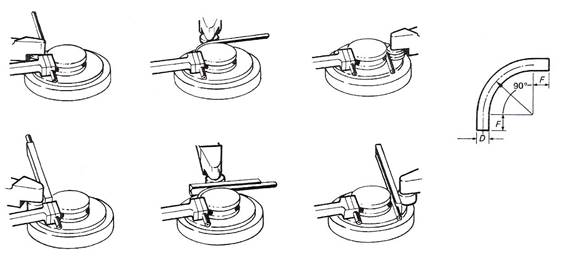
Figure 15 - Compression Bending using a Follow Block for Wiping the Pipe or Tube around the Bending Form
Machines of various types and sizes, worked by direct hand power, are capable of bending pipes up to 50 mm diameter. Some are so small, compact and light, that they are practically hand tools which can be easily transported and used on site work. Ratchet action or geared machines are used for large size pipework. For batch production, draw-bar machines are available. These machines have an adjustable mandrel that is pivoted at the outer end, supporting the walls of the pipe at the bending point, and is always tangential to the bend at that point whatever the radius of the former. Leverage is applied to the former, to which the pipe is attached, and the former itself revolves while the bend is being made. Some draw-bar machines are machine driven.
Figure 16 - Pipe Bending - Simple Bench Former
A former with a curvature to correspond with the required radius of the bend is bolted to the bench. One end of the loaded pipe is passed through the screwed eyelet provided, and the other end is forced downwards around the grooved former. Pipes up to 38mm diameter may be formed in this manner.
Figure 17 - Hot Bending
Figure 18 - Bending Press
A former to suit the size of the pipe to be bent is selected and secured to the end of the ram. When the pump is operated, the ram moves forward pressing the pipe against the die blocks, which are secured by pins in a steel frame. A series of locating holes in the frame permits the die blocks to be positioned correctly to accommodate pipes of various sizes.
Figure 18 illustrates the principle of a typical hydraulic machine used for press-bending thick-walled steel pipes.
Rotary type machines have two principle components: a quadrant former and a back guide, as shown in Figure 19(a), which enable pipes to be bent without loading. The former supports the throat of the pipe while the back guide rotates around the bend as pressure is applied by the roller. The sectional view in Figure 19(b) illustrates how these components support the pipe during the process, thus enabling the bend to be made without thickening of the throat metal which would reduce the bore of the pipe.
Figure 19 - Rotary Bending Machines
It is advisable, when using hand pull machines for heavy gauge pipes, to anneal the section to be bent and so save labour and undue stress on the machine.
Some machines are fitted with a device on the lever arm which, by proper adjustment, determines automatically the exact point at which pressure by the roller is best applied to the pipe. This device is the 'pointer'. Figure 19(c) shows the correct adjustment for bending. The pointer is parallel with the pipe when the roller is making tight contact with the back of the guide.
Figure 20 - Use of Springs for Bending
The pipe should be securely fixed or held in tongs, since it will become very hot when the molten lead is poured into it. The pipe should be warmed before pouring commences.
Great care must be taken to ensure that the pipe is thoroughly dry, especially if it has been quenched after annealing. If a pipe is at all damp, steam will be generated and its pressure will drive out the molten lead, with very grave risk to the operator.
Before use, sand should be thoroughly dry, any moisture in the sand may generate steam when the pipe is heated and thus may cause an explosion. Sand used for loading can be conveniently dried on a red-hot iron plate.
One of the simplest devices for hand bending small diameter pipes can be made by boring holes equal in diameter to the outer diameter of the pipe in a wood block or plank 76 mm to 100 mm in thickness. These are then gouged out to form easy bend channels in the thickness of the block. The pipe is gradually drawn through a suitable hole and forced downwards progressively in the channel, according to the sharpness of the bend required. Only easy cold bends on loaded pipes should be attempted using this method.
Between the outermost fibres and the neutral plane there is a zone where the strain produced is elastic.
On release of the bending force, that portion adjacent to the neutral plane loses its elastic stress, whilst the outer portions, which have suffered plastic deformation, remain as a permanent set. The elastic recovery of shape is known as 'SPRINGBACK'.
Figure 21 illustrates the effects of a bending force on a material. When bending sheet metal to an angle, the inner fibres of the bend are compressed and given COMPRESSION STRESSES. The outer fibres of the bend are stretched and given TENSILE STRESSES.
Figure 21 - The Effects of a Bending Force on a Material
Between the two stressed zones, which are in opposition to each other, lies a boundary which is a NEUTRAL PLANE. This boundary is termed the 'NEUTRAL AXIS' or 'NEUTRAL LINE' (see Figure 22).
The position of the neutral line will vary in different metals because of their differing properties, and also vary due to the thickness of the material and its physical condition. It is important to establish the position of the neutral line as it is required, in practice, for the purpose of calculating bend allowances.
Figure 22 - Bending Action - Pressure Bending
During the bending of a material an unbalanced system of varying stresses is produced in the region of the bend. When the bending force is removed (on completion of the bending operation) this unbalanced system tends to bring itself to equilibrium. The bend tends to spring back, and any part of the elastic stress which remains in the material becomes RESIDUAL STRESS in the bend zone.
The amount of springback action to be expected will obviously vary because of the differing compositions and mechanical properties of the materials used in fabrication engineering. Some materials, because of their composition, can undergo more severe cold-working than others.
The severity of bending a specific material depends on two basic factors:
A 'tight' (small radius) bend causes greater cold deformation than a more generous bend in a material of the same thickness.
A thicker material develops more STRAIN HARDENING than is experienced in thinner material bent to the same inside radius.
The 'condition' of the material upon which bending operations are to be performed, has an influence on the amount of springback likely to result. For example, using the same bend radius, a COLD-ROLLED NONHEAT-TREATABLE aluminium alloy in the 'HALF-HARD' temper, or condition, will exhibit greater springback than the same alloy of equal thickness when in the 'FULLY ANNEALED' condition.
The limit to which free bending can be carried out is determined by:
Figure 23 - Allowing for Springback on a Folding Machine
The first important point regarding the bending of a strip of sheet metal is the consideration of the direction of the grain in the metal. Owing to the rolling process, by which sheet metal is produced, there is a grain in the metal running lengthways in the strip or sheet, not unlike the grain in a piece of timber.
A bend should, whenever possible, be across this grain rather than along it, as there will be fewer tendencies for the metal to crack.
As most metals have a certain amount of natural spring the bend will have a tendency to open up after being bent, and to counteract this tendency a bending allowance is made on the angle of the top blade and the bottom vee die. For example, an 85° angle will be suitable for producing an angle of 90° on the workpiece.
If the angle required is to be accurate, then by using an air-gap die and by altering the depth of the stroke on the press brake this can be achieved. Test-pieces are first checked for the correct angle before proceeding with the production quota. A press brake may be stopped at any part of its stroke by engaging the brake or clutch. This enables the operator to position the work under the blade.
This chapter is concerned with the plastic manipulation of sheet metal at room temperature. Figure 24 shows some typical cold-forming operations.
Figure 24 - Comparison of Common Cold-Forming Applications
The terms 'folding' and 'bending' are rather loosely used in industry because they are so similar. The difference between them is so slight that they are both carried out with the same purpose in view, which is to deflect the metal from one flat plane to another so that it stays there permanently.
If the deflection is sharp, and the radius small, the metal is said to be folded. Should the curvature be large and the deflection covers a large area, it is called bending. In this respect the rolling of a hollow body, such as a cylinder, is called bending. Folding or bending involves the deformation of a material along a straight line in two dimensions only.
When a bending force is gradually applied to a workpiece under free bending conditions, the first stage of bending is elastic in character. This is because the TENSILE AND COMPRESSIVE stresses that are developed on opposite faces of the material are not sufficiently high to exceed the YIELD STRENGTH of the material. The movement or STRAIN which takes place as a result of this initial bending force is elastic only, and upon removal of the force the workpiece returns to its original shape.
As the bending force is continued and gradually increased, the stress produced in the outermost fibres (on both the compression and tension sides) of the material eventually exceeds the yield strength. Once the yield strength of the material has been exceeded, the movement (strain) which occurs is PLASTIC. This permanent strain occurs only in the outermost regions furthest from the NEUTRAL PLANE.
When metal is rolled into a circle, curved or bent by flanging or pressing, the outer radius of the material is always greater than the inside radius. This results in the fibres of the metal on the outside bend becoming stretched in tension, and the inside fibres becoming crushed in compression. Approximately midway between the two (this varies with very soft and hard metals) there is a line known as the neutral or mean line which is neither stretched nor compressed and remains the same length. It is important that this line is worked to when calculating metal length and allowance before rolling and bending.
Examples of the neutral line are given in Figure 25.
Figure 25 - Neutral Line
Source: http://local.ecollege.ie/Content/APPRENTICE/liu/metalfab_notes/module_3/Plate%20Forming%20Brake%20Press_M3_U1.doc
Web site to visit: http://local.ecollege.ie/
Author of the text: indicated on the source document of the above text
If you are the author of the text above and you not agree to share your knowledge for teaching, research, scholarship (for fair use as indicated in the United States copyrigh low) please send us an e-mail and we will remove your text quickly. Fair use is a limitation and exception to the exclusive right granted by copyright law to the author of a creative work. In United States copyright law, fair use is a doctrine that permits limited use of copyrighted material without acquiring permission from the rights holders. Examples of fair use include commentary, search engines, criticism, news reporting, research, teaching, library archiving and scholarship. It provides for the legal, unlicensed citation or incorporation of copyrighted material in another author's work under a four-factor balancing test. (source: http://en.wikipedia.org/wiki/Fair_use)
The information of medicine and health contained in the site are of a general nature and purpose which is purely informative and for this reason may not replace in any case, the council of a doctor or a qualified entity legally to the profession.
The texts are the property of their respective authors and we thank them for giving us the opportunity to share for free to students, teachers and users of the Web their texts will used only for illustrative educational and scientific purposes only.
All the information in our site are given for nonprofit educational purposes