In the construction industry all drawings are carried out to a British Standard referred to as BS 1192. This ensures that every drawing produced within Ireland and the UK relating to a building project will follow the same standard principles.
Dimensions should be shown as follows:


The conventions relating to dimensions are as follows:
Give metric dimensions to the least number of significant figures, for example;
2.5 not 2.50
3 not 3.0
Dimensions less than 1 are expressed with a zero preceding the decimal point;
0.5 not 5
All drawings require some form of lettering and numbers. The principles to remember are:
One of the most important features of any drawing is the border and title block. The border (or margin) is a line which follows the outer edge of the drawing and is usually 10 or 20mm inside it. This margin is very important because everything inside it forms part of any contract.
The ‘Title Block’ is locked within the boarder and contains information such as:
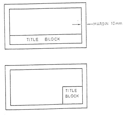 Title Blocks are usually located along the bottom or sides of drawings as shown below:
A scale can be used to increase the detail of a small object or to accurately represent a large object on a smaller piece of paper. The majority of scaled work done in the construction industry is to reduce objects to a smaller more suitable size that will fit on a sheet of paper.
The list below shows the scales used in BS 1192:
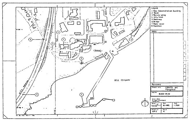
Here is a drawing of Block Plan originally drawn at 1:2500 but printed not to scale (NTS).
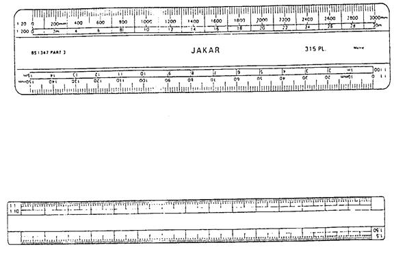 As already stated, the scale of the drawing will be indicated in the block. To take measurements from such a drawing a ‘Scale Rule’ is used. Scale rules are usually manufactured from plastic and have several scales indicated on the ends as shown below.
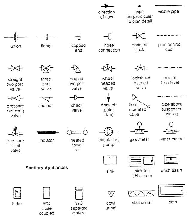
In order to read a drawing properly, and to understand what is happening, an agreed set of graphical symbols and abbreviations are used. All the different trades have a set of symbols pertaining to their respective works. The works of the plumber is often referred to as the “Mechanical Services”.
The Mechanical Services includes:
When pipes and their relative components are shown on a drawing it is vitally important that the craftsperson can correctly identify their locations and positions. The symbols for the location of pipes in a building are as follows:
Pipes at low level _________________________________
Pipes at high level ___ ___ ___ ___ ___ ___ ___
Pipes in roof or above ceiling ___ ___ ___ ___ ___ __
Pipes below floor or underground _ _ _ _ _ _ _ _ _ _ _ _ _ _ _ _ _
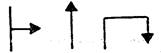
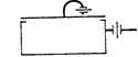
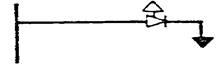
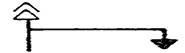
When pipes rise or drop to a ![]() different level they are shown
different level they are shown
![]()
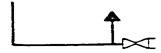
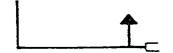
![]() To show the direction of flow
To show the direction of flow
In order to know if the pipe rises or drops the following abbreviations will be used:
TA |
To Above |
FB |
From Below |
RTA |
Rise To Above |
DTB |
Drop To Below |
To identify individual services some of the following abbreviations may be used.
MWS |
Mains Water Services |
DW |
Drinking Water |
CWF |
Cold Water Flow |
CWS |
Cold Water Service |
HWSF |
Hot Water Service Flow |
HWSR |
Hot Water Service Return |
HWSVP |
Hot Water Service Vent Pipe |
FF |
Fire Fighting Services |
HRS |
Hose Reel Service |
CA |
Compressed Air |
F&R |
Flow and Return |
The symbols on the following pages are from the British Standards Institution and are used extensively in drawings relating to mechanical services.
Symbol |
Description |
Application |
|
Draw-off tap |
|
|
Shower head |
|
|
Sprinkler head |
|
|
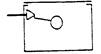
Float-operated valve |
|
|
Float switch (Hydraulic type) |
|
|
Float switch (Magnetic type) |
|
|
Filter or screen |
|
|
Supply stopvalve (SV) |
|
|
Servicing valve (SV) |
|
|
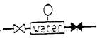
Water meter |
|
Symbol |
Description |
Application |
|
Draining valve (BS 1192) |
|
|
Draining valve (Abbreviated version used in this book) |
|
|
Line Strainer |
|
|
Pressure reducing valve (Small end denotes high pressure) |
|
|
Expansion vessel |
|
|
Pressure relief valve |
|
|
Check valve or non-return valve (NRV) |
|
|
Double check valve assembly |
|
|
Combined check and anti-vacuum valve (check valve and vacuum breaker) |
|
|
Air inlet valve |
|
Symbol |
Description |
Application |
|
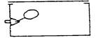
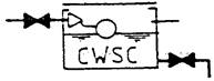
Cold water storage cistern |
|
|
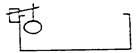
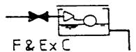
Feed and expansion cistern |
|
|
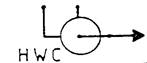
Hot water storage cylinder or tank (plan) |
|
|
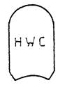
Hot water storage cylinder or hot store vessel (Direct types) |
|
|
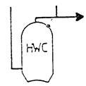
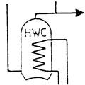
Hot water storage cylinder or hot store vessel (indirect types) (elevation) |
|
|
Boiler (elevation) |
|
|
Temperature relief valve |
|
|
Tundish |
|
In addition to installing drawings most large construction projects will also have a ‘SPECIFICATION’ to which the craftsman will have to refer. The specification will give more information relating to the installation.
There are many advantages to having a specification for a project, for example:
Specification will normally include the following information:
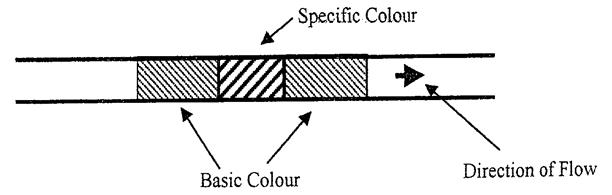
In large plumbing and heating installations it may be difficult to correctly identify what services pipes are supplying. A system of colour coding has been designed which enables pipe contents to be identified. The chart below shows the different colours that apply to the various services.
Pipe Contents |
Basic Colour |
Specific Colour |
Basic Colour |
Untreated Water |
Green |
Green |
Green |
Drinking Water |
Green |
Blue |
Green |
Hot Water Supply |
Green |
Whit-Crimson-White |
Green |
Heating Pipes |
Green |
White-Crimson-Blue |
Green |
Steam |
Silver Grey |
Silver Grey |
Silver Grey |
Condensate |
Green |
Crimson-Green-Crimson |
Green |
Natural Gas |
Yellow |
Yellow |
Yellow |
Diesel Fuel Oil |
Brown |
White |
Brown |
Compressed Air |
Light Blue |
Light Blue |
Light Blue |
Occasionally it will also be necessary to indicate the direction of flow on a pipe. This is shown by an arrow situated close to the colour code. In the case of central heating pipe-work the word FLOW or the letter F may be shown on one pipe and RETURN or R on the other.
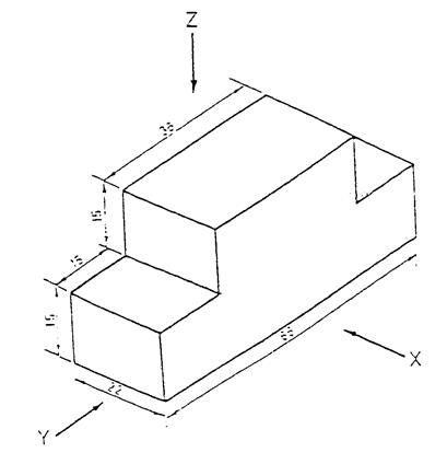
Orthographic projection shows the views of an object in three different positions, namely: PLAN – ELEVATION – END VIEW.
The plan is an outline of the object when viewed from above.
The elevation is what is seen when looking from the front.
The end view shows the view from one of the ends.
Orthographic projection is generally not used in the construction industry. It is more commonly found in the engineering sector where precise measurement is essential.
Try drawing the object below in orthographic projection i.e. draw a plan (z) an elevation (x) and an end view (y).
In isometric projection all the horizontal lines are drawn at 30° to the horizontal plane while vertical lines are drawn vertical.
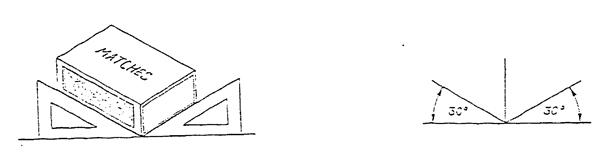 Isometric projection embraces the three views from orthographic projection in the one drawing. In the drawing of the matchbox below you can see the plan, elevation and end view.
Isometric projection is often used in the plumbing industry to show pipe runs.
The drawing on the next page is an extract from BS 1192 Part 2 : 1987 with the pipe-work shown in the isometric projection.
Complete the symbol and applications boxes in the table below.
Symbol |
Description |
Application |
|
Draw-off tap |
|
|
Shower head |
|
|
Sprinkler head |
|
|
Float-operated valve |
|
|
Float switch (Hydraulic type) |
|
|
Float switch (Magnetic type) |
|
|
Filter or screen |
|
|
Supply stopvalve (SV) |
|
|
Servicing valve (SV) |
|
|
Water meter |
|
Symbol |
Description |
Application |
|
Draining valve (BS 1192) |
|
|
Draining valve (Abbreviated version used in this book) |
|
|
Line Strainer |
|
|
Pressure reducing valve (Small end denotes high pressure) |
|
|
Expansion vessel |
|
|
Pressure relief valve |
|
|
Check valve or non-return valve (NRV) |
|
|
Double check valve assembly |
|
|
Combined check and anti-vacuum valve (check valve and vacuum breaker) |
|
|
Air inlet valve |
|
Symbol |
Description |
Application |
|
Cold water storage cistern |
|
|
Feed and expansion cistern |
|
|
Hot water storage cylinder or tank (plan) |
|
|
Hot water storage cylinder or hot store vessel (Direct types) |
|
|
Hot water storage cylinder or hot store vessel (indirect types) (elevation) |
|
|
Boiler (elevation) |
|
|
Temperature relief valve |
|
|
Tundish |
|
Source: http://local.ecollege.ie/Content/APPRENTICE/liu/Plumbing_notes/Scales_Drawings_M1_U5.doc
Web site to visit: http://local.ecollege.ie/
Author of the text: indicated on the source document of the above text
If you are the author of the text above and you not agree to share your knowledge for teaching, research, scholarship (for fair use as indicated in the United States copyrigh low) please send us an e-mail and we will remove your text quickly. Fair use is a limitation and exception to the exclusive right granted by copyright law to the author of a creative work. In United States copyright law, fair use is a doctrine that permits limited use of copyrighted material without acquiring permission from the rights holders. Examples of fair use include commentary, search engines, criticism, news reporting, research, teaching, library archiving and scholarship. It provides for the legal, unlicensed citation or incorporation of copyrighted material in another author's work under a four-factor balancing test. (source: http://en.wikipedia.org/wiki/Fair_use)
The information of medicine and health contained in the site are of a general nature and purpose which is purely informative and for this reason may not replace in any case, the council of a doctor or a qualified entity legally to the profession.
The texts are the property of their respective authors and we thank them for giving us the opportunity to share for free to students, teachers and users of the Web their texts will used only for illustrative educational and scientific purposes only.
All the information in our site are given for nonprofit educational purposes