
Technical drawing is also referred to as the "language of sight". It can be learnt to illustrate objects, functions or arrangements unambiguously and clearly. The main function of a drawing is to transfer information from the design team to the construction team and present the information in a user friendly legible format. Depending on the information to be transferred drawings can range from a simple hand sketch to a detailed 3D model. The following list identifies the types of drawings commonly used in the pipefitting industry:
Architectural / Civil drawings: Architectural drawings present information about the conceptual design of the building or structure. Examples are civil plans of a facility, building elevations (outside view of each side of a structure), foundation drawings, and sectional elevation drawings showing finished floor levels, main pipe rack levels and finished ceiling levels.
General arrangement (GA) drawings: are orthographic views of the overall facility which show the inter relationship the equipment and piping with the Architectural / Civil drawings. They are usually the controlling reference documents from which the other piping drawings are derived from. The GAs are also used by the other crafts such as the electricians to plan their work such as routing conduit, instrument tubing or electrical bundles.
Isometric drawings: are derived from the GA drawings and are used to subdivide a piping system into smaller manageable spools which are suitable for pre-fabrication. For high purity systems which require weld traceability these drawings are usually used as weld maps to record the positions of welds and what welder completed them.
Free hand sketches: often used in the field to convey or clarify minor points of information between engineers and pipe fitters. Pipe fitters also need to know how to draw free hand sketches as they may need to bring information back to update system drawings with changes that were made in the field.
Standard detail drawings: These drawings are used to detail standard recurring requirements such as ope penetrations, bracketing support or anchor details. These drawings would be agreed with the client and kept in a central file for reference when ever required.
3D Models: The advent of computers and CAD packages have allowed designers to model the complete building, process equipment and interconnecting pipework.
Orthographic projection is widely used for fabrication and construction type drawings, as shown in Figure 1. Orthographic projections present the component or system through the use of three views, These are a top view, a side view, and a front view. Other views, such as a bottom view, are used to more fully depict the component or system when necessary.
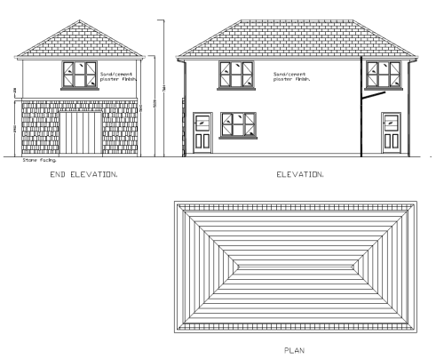
Figure 1 – Typical orthographic representation of a building
Figure 2 shows how each of the three views is obtained. The orthographic projection is typically drawn to scale and shows all components in their proper relationships to each other. The three views, when provided with dimensions and a drawing scale, contain information that is necessary to fabricate or 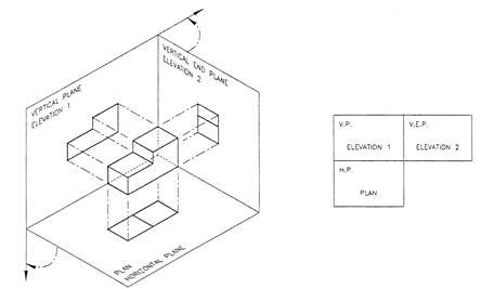
construct the component or system.
Figure 2 –Orthographic projection of 3 views of a solid object
The isometric projection presents a single view of the component or system. The view is commonly from above and at an angle of 30°. This provides a more realistic three dimensional view. As shown on Figure 3, this view makes it easier to see how the system looks and how its various portions or parts are related to one another. Isometric projections may or may not be drawn to a scale.
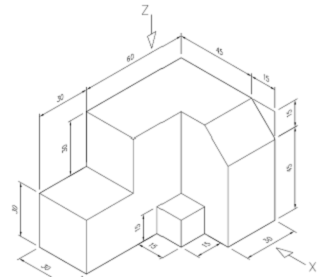
Figure 3 –Isometric drawing of a solid object
Isometric drawings are commonly used to give clarity to complicated pipe spools with a lot of detail and different piping components. Before the introduction of CAD these were normally completed as line isometrics as seen in Figure 4a, however with proficient use of 3D CAD packages which have extensive component libraries it is a relatively simple task to complete a pictorial isometric as illustrated in Figure 4b.
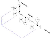
Figure 4a –Line isometric of pipe spool. Figure 4b Pictorial isometric of pipe spool
Parallel line development is used to develop patterns of square, rectangular and cylindrical shapes (prisms). The method divides the surface into a series of parallel lines to determine the shape of a pattern. Figure 5 below illustrates how the parallel line development of a truncated cylinder is developed.
The circumference of the circle is divided into 12 equal spaces which is stretched out in the right hand view. The parallel lines give us the chord lengths which are projected over to the stretch out chords, which represent chords on the circumference of the cylinder. This gives us a series of heights which are joined by freehand to give a true shape development of the surface of the cylinder. Essentially it is 'unfolding' the cylindrical shape from three dimensions into two dimensions.
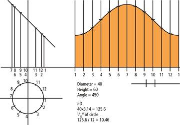
Figure 5 –Parallel line development of a truncated cylinder
Parallel line development is used for the pattern development of pipe work, prisms, and any cylindrical shape. Pattern development can be marked directly onto flat metal plate. The metal is then formed to shape. Patterns are often turned into templates using paper or thin sheet steel. On formed stock pipe, the pattern becomes a wrap around template, and can be used over and over again. Often with cylindrical pipe work, the sizes are outside the range of available stock pipe. In that case, the cylinder must be formed from flat plate, using the pattern to establish the required shape.
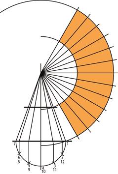
The radial line method of pattern development is used to develop patterns for objects that have a tapering form with lines converging to a common point, called the apex point. The radial line method uses a series of radial generator lines drawn from a common apex point to develop a specified pattern or shape. Radial line development is used for conical shapes, that is, where a shape converges to an apex point (at a workable distance).
Figure 6 –Radial line development of a truncated cone
Figure 6 above illustrates how the radial line development of a truncated cone is completed. Two arcs are drawn using the apex as the centre point and the base of the cone as the external radius and the base of the truncated cone as the internal radius. The cone is divided into 12 equal spaces which are marked 12 times along the larger arc. These are then joined to the apex to give a true shape development of truncated cone surface. This method of drawing is often used for the development of patterns for pipe reducers or large conical hoppers.
Title |
Author |
Ref. Code |
The Induction Book, “Code of Behaviour & Health & Safety Guidelines” |
SOLAS |
|
Basic Welding and Fabrication |
W Kenyon |
ISBN 0-582-00536-L |
Fundamentals of Fabrication and Welding Engineering |
FJM Smith |
ISBN 0-582-09799-1 |
Workshop processes, practices and materials, 3rd edition, Elsevier Science & Technology |
Black, Bruce J 2004 |
ISBN-13: 9780750660730 |
New Engineering Technology |
Lawrence Smyth & Liam Hennessy |
ISBN 086 1674480 |
Source: http://local.ecollege.ie/Content/APPRENTICE/liu/pipefitting/word/M5_U1_Drawing%20methods%20and%20types.doc
Web site to visit: http://local.ecollege.ie/
Author of the text: indicated on the source document of the above text
If you are the author of the text above and you not agree to share your knowledge for teaching, research, scholarship (for fair use as indicated in the United States copyrigh low) please send us an e-mail and we will remove your text quickly. Fair use is a limitation and exception to the exclusive right granted by copyright law to the author of a creative work. In United States copyright law, fair use is a doctrine that permits limited use of copyrighted material without acquiring permission from the rights holders. Examples of fair use include commentary, search engines, criticism, news reporting, research, teaching, library archiving and scholarship. It provides for the legal, unlicensed citation or incorporation of copyrighted material in another author's work under a four-factor balancing test. (source: http://en.wikipedia.org/wiki/Fair_use)
The information of medicine and health contained in the site are of a general nature and purpose which is purely informative and for this reason may not replace in any case, the council of a doctor or a qualified entity legally to the profession.
The texts are the property of their respective authors and we thank them for giving us the opportunity to share for free to students, teachers and users of the Web their texts will used only for illustrative educational and scientific purposes only.
All the information in our site are given for nonprofit educational purposes