Definitions
Normal Supply: An electricity supply taken from the supply authority ( DSO ) or alternatively from the proprietor’s own generating plant
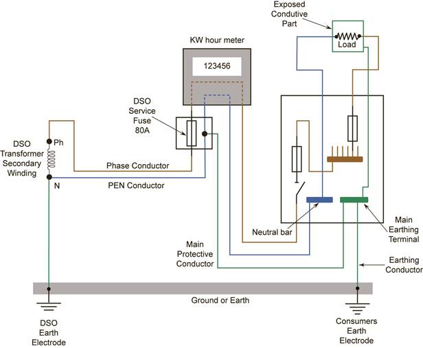
Earthing: The connection of the exposed conductive parts of an installation to the main earthing terminal or bar.
Main Earthing Terminal ( MET ) or Bar: A terminal or bar provided for the connection of protective conductors, main equipotential bonding conductors and conductors for functional earthing if any, to the means of earthing.
Main Protective Conductor: A conductor that connects the main earthing terminal or bar to the supply neutral.
Earthing Conductor: A conductor connecting the main earthing terminal or bar to the earth electrode.
Earth Electrode: A conductive part or a group of conductive parts in intimate contact with, and providing an electrical connection with, earth.
PEN Conductor: An earthed conductor combining the functions of both protective conductor and neutral conductor.
Note: The acronym PEN comes from the combination of the symbols PE for the protective conductor and N for the neutral conductor.
Bonding: See Equipotential Bonding.
Equipotential Bonding: Electrical connections intended to maintain exposed conductive parts and extraneous conductive parts at the same or approximately the same potential, but not intended to carry current in normal service.
Equipotential Bonding Conductor: A protective conductor for ensuring equipotential bonding.
Earthing
Earthing is defined as “The connection of the exposed conductive parts of an installation to the main earthing terminal”.
Main Earthing Terminal
Main Protective Conductor
Earthing Conductor
Protective Conductor
All circuits unless specifically designed for a non-conducting location will have a protective conductor ( PE ) included. They must be capable of carrying the maximum possible earth fault current to the DSO neutral, via the main earthing terminal.
They only have to carry this fault current for the time required to operate the circuit protective device. In general, this time will not exceed five seconds. In the event of a fault, they prevent exposed conductive parts becoming live with respect to earth.
The protective conductor may be a:
See Figure 1.
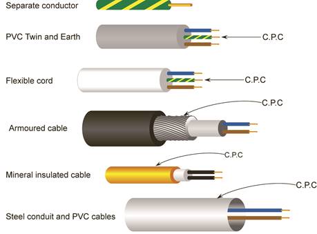
Figure 1.
Earth Electrode
Figure 2 |
Figure 3 |
Function of the Earth Electrode
The function of the earth electrode is to maintain a connection between the general mass of earth and metallic parts of the consumer’s installation. These can then be regarded as being at zero potential. The earth electrode must be continuously effective and capable of carrying earth leakage and earth fault currents, which may arise.
Location and Installation of the Earth Electrode
Waterproof Tape
Denso tape is generally used to protect the termination at the earth electrode. Although it is easily applied, it leaves a sticky residue on everything it comes into contact with. It has stood the test of time. Terminations have been found to be in excellent condition after exposure to arduous conditions for many years. It provides protection against the ingress of water and against damage by chemical action, rodents and termites.
Another form of protection, which may be used is a self-amalgamating tape. This tape relies on an internal chemical action between its layers. The action of stretching the tape around a connection activates a chemical process. After a period of about thirty minutes the tape will have formed into a solid rubber mass around the connection.
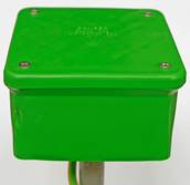
Earth Electrode Connection
Figure 5 shows a suitable type enclosure for housing the earth electrode connection.
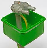
Figure 6 shows the earthing conductor connected to the earth electrode.
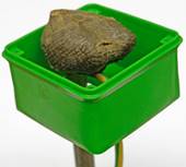
Figure 7 shows the connection protected by Denso tape.
Types of System Earthing
There are three types of system earthing used today.
These are: -
conductor of the supply system. In AC systems the earthed
conductor is normally the neutral conductor.
( known as PEN conductor )
TN-C-S System
TN-C-S System Earthing
Equipotential Bonding
Main Equipotential Bonding
Main equipotential bonding connects together all conductive parts of the main engineering services in an installation, to the main earthing terminal. Examples of the main engineering services are:
Supplementary Equipotential Bonding
Supplementary equipotential bonding is generally applied to a location in an installation. It connects together all extraneous conductive parts and all exposed conductive parts in the location.
Water may conduct electricity. Extra safety measures should be applied to locations where electrical equipment is used in close proximity to water or steam. Kitchens, utility rooms, bathrooms and shower rooms are such locations.
Equipotential Bonding in a Kitchen / Utility Room
In kitchens and utility rooms, all extraneous conductive parts such as metal sinks and metal pipes must be bonded together. This equipotential bond must then be connected to a local protective conductor.
|
Figure 11
Note: Even if both pipes are plastic the sink must be bonded.
Equipotential Bonding in a Shower or Bathroom
Showers and baths provide an increased risk of shock hazard due to the reduction of body resistance ( skin wet ) and the possibility of contact with earth potential. Extraneous conductive parts and exposed conductive parts in an area containing a shower or bath are treated as being within zoned areas.
|
Figure 12.
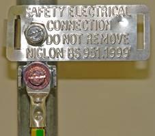
Bonding Clip
The type of bonding clip used is corrosion resistant and adjustable to fit several sizes of pipe. A locking device is provided to ensure that the clip cannot work loose through expansion / contraction caused by heating / cooling or by vibration. The pipe should be first cleaned to remove any residue from building materials or oxidisation that may have built up over years on an older installation. The clip should be tightly fitted and the locking device secured to ensure good electrical contact with the pipe. A terminal is provided for the electrical connection to be made. This connection must be properly terminated, taking into account the type and size of conductor(s) involved. A metallic label must be fitted with the words “SAFETY ELECTRICAL CONNECTION DO NOT REMOVE” embossed on it.
See Figure 13.
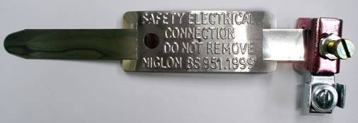
Figure 13
Figure 14 shows a main bonding conductor connection.
|
Source: http://local.ecollege.ie/Content/APPRENTICE/liu/electrical_notes/LL226.doc
Web site to visit: http://local.ecollege.ie
Author of the text: indicated on the source document of the above text
If you are the author of the text above and you not agree to share your knowledge for teaching, research, scholarship (for fair use as indicated in the United States copyrigh low) please send us an e-mail and we will remove your text quickly. Fair use is a limitation and exception to the exclusive right granted by copyright law to the author of a creative work. In United States copyright law, fair use is a doctrine that permits limited use of copyrighted material without acquiring permission from the rights holders. Examples of fair use include commentary, search engines, criticism, news reporting, research, teaching, library archiving and scholarship. It provides for the legal, unlicensed citation or incorporation of copyrighted material in another author's work under a four-factor balancing test. (source: http://en.wikipedia.org/wiki/Fair_use)
The information of medicine and health contained in the site are of a general nature and purpose which is purely informative and for this reason may not replace in any case, the council of a doctor or a qualified entity legally to the profession.
The texts are the property of their respective authors and we thank them for giving us the opportunity to share for free to students, teachers and users of the Web their texts will used only for illustrative educational and scientific purposes only.
All the information in our site are given for nonprofit educational purposes