
Ammeter:
An ammeter is a measuring instrument used to measure the electric current in a circuit. Electric currents are measured in amperes (A), hence the name. Instruments used to measure smaller currents, in the milliampere or microampere range, are designated as milliammeters or microammeters. Early ammeters were laboratory instruments which relied on the Earth's magnetic field for operation. By the late 19th century, improved instruments were designed which could be mounted in any position and allowed accurate measurements in electric power systems.
Ammeter
Voltmeter:
A voltmeter is an instrument used for measuring electrical potential difference between two points in an electric circuit. Analog voltmeters move a pointer across a scale in proportion to the voltage of the circuit; digital voltmeters give a numerical display of voltage by use of an analog to digital converter
.
Voltmeter
Voltmeters are made in a wide range of styles. Instruments permanently mounted in a panel are used to monitor generators or other fixed apparatus. Portable instruments, usually equipped to also measure current and resistance in the form of a multimeter, are standard test instruments used in electrical and electronics work. Any measurement that can be converted to a voltage can be displayed on a meter that is suitably calibrated; for example, pressure, temperature, flow or level in a chemical process plant.
General purpose analog voltmeters may have an accuracy of a few percent of full scale, and are used with voltages from a fraction of a volt to several thousand volts. Digital meters can be made with high accuracy, typically better than 1%. Specially calibrated test instruments have higher accuracies, with laboratory instruments capable of measuring to accuracies of a few parts per million. Meters using amplifiers can measure tiny voltages of microvolts or less.
Wattmeter:
The wattmeter is an instrument for measuring the electric power (or the supply rate of electrical energy) in watts of any given circuit. Electromagnetic wattmeters are used for measurement of utility frequency and audio frequency power; other types are required for radio frequency measurements.
Electrodynamic
Early wattmeter on display at the Historic Archive and Museum of Mining in Pachuca, MexicoThe traditional analog wattmeter is an electrodynamic instrument. The device consists of a pair of fixed coils, known as current coils, and a movable coil known as the potential coil. The current coils connected in series with the circuit, while the potential coil is connected in parallel. Also, on analog wattmeters, the potential coil carries a needle that moves over a scale to indicate the measurement. A current flowing through the current coil generates an electromagnetic field around the coil. The strength of this field is proportional to the line current and in phase with it. The potential coil has, as a general rule, a high-value resistor connected in series with it to reduce the current that flows through it. |
Power Supply
A power supply is a device that supplies electric power to an electrical load. The term is most commonly applied to electric power converters that convert one form of electrical energy to another, though it may also refer to devices that convert another form of energy (mechanical, chemical, solar) to electrical energy. A regulated power supply is one that controls the output voltage or current to a specific value; the controlled value is held nearly constant despite variations in either load current or the voltage supplied by the power supply's energy source.
Every power supply must obtain the energy it supplies to its load, as well as any energy it consumes while performing that task, from an energy source. Depending on its design, a power supply may obtain energy from:
• 16 A, 30 mA differential magneto-thermal main switch
• key operated emergency push-button
• start and stop push-buttons
• motor protection circuit breaker: 6.3 to 10 A
• digital ammeter and digital switchable voltmeter
• ac output: 3 x 0 ... 380 V, 8 A
The output voltage is set by a rotary knob with 0-100% scale.
Supply voltage: three-phase from mains.
DC power supply
An AC powered unregulated power supply usually uses a transformer to convert the voltage from the wall outlet (mains) to a different, nowadays usually lower, voltage. If it is used to produce DC, a rectifier is used to convert alternating voltage to a pulsating direct voltage, followed by a filter, comprising one or more capacitors, resistors, and sometimes inductors, to filter out (smooth) most of the pulsation. A small remaining unwanted alternating voltage component at mains or twice mains power frequency (depending upon whether half- or full-wave rectification is used)—ripple—is unavoidably superimposed on the direct output voltage.
Fig: DC Power Supply
Digital Multimeter:
DMM (UT55 Multimeter) is used for the Calculation of
To understand the nameplate data of Electrical Machines.
Objective:
Upon the successful of lab session students will be able to understand
Theory:
Nameplate Data:
The National Electrical Manufacturer's Association (NEMA) specifies that every motor nameplate must show these specific items
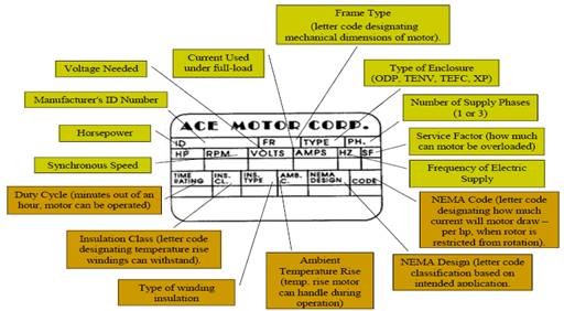 Line voltage will fluctuate due to a variety of factors. Therefore, every motor must be designed to handle these voltage variations. Tatung motors can withstand voltage variation of plus or minus 10%, so a 230 Volt motor could operate between approximately 207 to 253 volts. At these extremes, no motor will run at its peak performance; however it will withstand these conditions.
S = (120 x F)/P
S = speed in RPM
F = frequency in hertz
P = No of poles in motor
Or, if you know the number of poles in your motor, you can determine the speed by the following chart:
No of Poles |
Synchronous Speed |
Actual Speed |
2 |
3600 |
3450 |
4 |
1800 |
1725 |
6 |
1200 |
1140 |
8 |
900 |
850 |
Class |
20,000 Hour Life Temperature |
A |
105°C |
B |
130°C |
F |
155°C |
H |
180°C |
1 |
30 |
300 |
1250 |
1 ½ |
40 |
350 |
1500 |
2 |
50 |
400 |
1750 |
3 |
60 |
450 |
2000 |
5 |
75 |
500 |
2250 |
7 ½ |
100 |
600 |
2500 |
10 |
125 |
700 |
3000 |
15 |
150 |
800 |
3500 |
20 |
200 |
900 |
4000 |
25 |
250 |
1000 |
When application horsepower requirements fall between two standardized values, the larger size is usually chosen.
The work capacity of a horse was used to define the power of an electric motor. It was determined that a horse could lift 1000 pounds, 33', in one minute. It is the amount of work done in a given amount of time. The formula is:
HP = (Foot #s Per Minute) \ 33,000 -or- HP= (Foot #s per second) \ 550
Code |
KVA/HP |
Approx. Mid-Range Value |
A |
0.00-3.14 |
1.6 |
B |
3.15-3.54 |
3.3 |
C |
3.55-3.99 |
3.8 |
D |
4.00-4.49 |
4.3 |
E |
4.50-4.99 |
4.7 |
F |
5.00-5.59 |
5.3 |
G |
5.60-6.29 |
5.9 |
H |
6.30-7.09 |
6.7 |
J |
7.10-7.99 |
7.5 |
K |
8.00-8.99 |
8.5 |
L |
9.00-9.99 |
9.5 |
M |
10.00-11.99 |
10.6 |
N |
11.20-12.49 |
11.8 |
P |
12.50-13.99 |
13.2 |
R |
14.00-15.99 |
15.0 |
Using this chart and the job voltage, you can calculate the across the line starting inrush by using the following:
200 Volts LRA = Code letter value x HP x 2.9
230 Volts LRA = Code letter valve x HP x 2.5
460 Volts LRA = Code letter value x HP x 1.25
NEMA Design A motors has normal starting torques, but high starting currents. This is useful for applications with brief heavy overloads. Injection molding machines are a good application for this type of motor. Many of the Tatung design B motors can handle Design A requirements!
NEMA Design B motors are the most common. They feature normal starting torque combined with a low starting current. These motors have sufficient locked rotor torques to start a wide variety of industrial applications.
NEMA Design C motors have high starting torques with low starting currents. They are designed for starting heavy loads due to their high locked rotor torques and high full load slip.
NEMA Design D motors have high starting torque and low starting current, however they feature high slip. This reduces power peaks in the event that peak power is encountered, motor slip will increase.
To understand the constructional parts of DC Machines with their functional details
Objectives:
After the successful completion of the lab session students will be understand
Equipment Required:
DC Machines Introduction:
DC machines are either generators or motors. DC generator is electrical equipment that covert mechanical energy to electrical energy and vice versa foe DC motors. Most of the DC machines are like AC machines, they have same AC voltage and AC current as input but DC voltage and current as output. This is done using the commutator segments, which convert ac into dc and used as mechanical rectifiers.
DC Machines as Motor:
 When a current carrying conductor is placed in a magnetic field; it experiences a torque and has a tendency to move. This is known as motoring action. If the direction of electric current in the wire is reversed, the direction of rotation also reverses. When magnetic field and electric field interact they produce a mechanical force, and based on that the working principle of dc motor established. The direction of rotation of a this motor is given by Fleming’s left hand rule, which states that if the index finger, middle finger and thumb of your left hand are extended mutually perpendicular to each other and if the index finger represents the direction of magnetic field, middle finger indicates the direction of electric current, then the thumb represents the direction in which force is experienced by the shaft of the dc motor.
The force extended on conductor is given as
F=B×I×L
Where
F=Force in Newton (N)
B=Magnetic flux density in tesla (T)
I = Current in Amperes (A)
L= Length in meter (m)
When above equation is applied to conductor around the armature the toque applied to armature conductors and therefore to the shaft of the machine can be determined. The amount of torque can be determined from equation blow
T=K×Φ×Ia
Where
T= Torque in newton meter (Nm)
K=Machine constant
Φ=magnetic flux/pole in weber (Wb)
Ia=Total armature in Ampere (A)
DC Motor Types
Chart blow will clear the idea.
As the name suggests, in case of a separately excited DC Motor the supply is given separately to the field and armature windings. The main distinguishing fact in these types of dc motor is that, the armature current does not flow through the field windings, as the field winding is energized from a separate external source of dc current as shown in the figure beside.
From the torque equation of dc motor we know Tg= Ka φ Ia So the torque in this case can be varied by varying field flux φ, independent of the armature current Ia.
The permanent magnet DC motor consists of an armature winding as in case of a usual motor, but does not necessarily contain the field windings. The construction of these types of DC motor is such that radially magnetized permanent magnets are mounted on the inner periphery of the stator core to produce the field flux. The rotor on the other hand has a conventional dc armature with commutator segments and brushes. The diagrammatic representation of a permanent magnet dc motor is given below.
The torque equation of dc motor suggests Tg= Ka φ Ia. Here φ is always constant, as permanent magnets of required flux density are chosen at the time of construction and can’t be changed thereafter.
∴ for a permanent magnet dc motor Tg= Ka1Ia
Where Ka1 = Ka.φ which is another constant. In this case the torque of DC Motor can only be changed by controlling armature supply.
In case of self-excited dc motor, the field winding is connected either in series or in parallel or partly in series, partly in parallel to the armature winding, and on this basis its further classified as:-
i) Shunt Wound DC Motor
ii) Series Wound DC Motor
iii) Compound Wound DC Motor
let’s now go into the details of these types of self-excited dc motor.
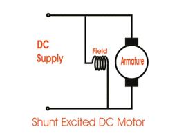 In case of ashunt wound dc motor or more specifically shunt wound self-excited dc motor, the field windings are exposed to the entire terminal voltage as they are connected in parallel to the armature winding as shown in the figure.
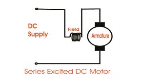 In case of a series wound self-excited dc motor or simply series wound dc motor, the entire armature current flows through the field winding as its connected in series to the armature winding. The series wound self-excited dc motor is diagrammatically represented below for clear understanding.
The compound excitation characteristic in a dc motor can be obtained by combining the operational characteristic of both the shunt and series excited dc motor. The compound wound self-excited dc motor or simply compound wound dc motor essentially contains the field winding connected both in series and in parallel to the armature winding as shown in the figure below: The excitation of compound wound dc motor can be of two types depending on the nature of compounding.
When the shunt field flux assists the main field flux, produced by the main field connected in series to the armature winding then it’s called cumulative compound dc motor.
φtotal = φseries + φshunt
In case of a differentially compounded self-excited dc motor i.e. differential compound dc motor, the arrangement of shunt and series winding is such that the field flux produced by the shunt field winding diminishes the effect of flux by the main series field winding.
φtotal = φseries - φshunt
The compounding characteristic of the self-excited dc motor is shown in the figure below
Both the cumulative compound and differential compound dc motor can either be of short shunt or long shunt type depending on the nature of arrangement.
If the shunt field winding is only parallel to the armature winding and not the series field winding then it’s known as short shunt dc motor or more specifically short shunt type compound wound dc motor.
If the shunt field winding is parallel to the armature winding and the series field winding then it’s known as long shunt type compounded wound dc motor or simply long shunt dc motor.
Short shunt and long shunt type motors have been shown in the diagram below.
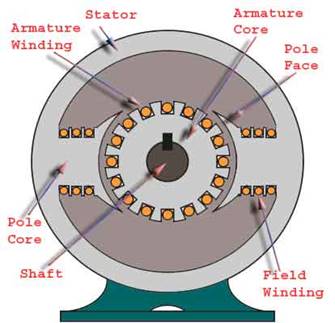
Constructional Parts:
1. Stators:
The static part that houses the field winding and receives the supply is called stator.
2. Rotor:
The rotating part that bring about the mechanical rotations.
Other than that there are several subsidiary parts namely the
3) Yoke of dc motor.
4) Poles of dc motor.
5) Field winding of dc motor.
6) Armature winding of dc motor.
7) Commutator of dc motor.
8) Brushes of dc motor.
Yoke of dc motor
The magnetic frame or the yoke of dc motor made up of cast iron or steel and forms an integral part of the stator or the static part of the motor. Its main function is to form a protective covering over the inner sophisticated parts of the motor and provide support to the armature. It also supports the field system by housing the magnetic poles and field windings of the dc motor.
Poles of dc motor
The magnetic poles of DC motor are structures fitted onto the inner wall of the yoke with screws. The construction of magnetic poles basically comprises of two parts namely, the pole core and the pole shoe stacked together under hydraulic pressure and then attached to the yoke. These two structures are assigned for different purposes, the pole core is of small cross sectional area and itsfunction is to just hold the pole shoe over the yoke, whereas the pole shoe having a relatively larger cross-sectional area spreads the flux produced over the air gap between the stator and rotor to reduce the loss due to reluctance. The pole shoe also carries slots for the field windings that produce the field flux.
Field Winding of DC Motor
The field winding of dc motor are made with field coils (copper wire) wound over the slots of the pole shoes in such a manner that when field current flows through it, then adjacent poles have opposite polarity are produced. The field windings basically form an electromagnet, that produces field flux within which the rotor armature of the dc motor rotates, and results in the effective flux cutting
Armature winding of DC Motor
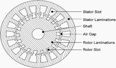
The armature winding of dc motor is attached to the rotor, or the rotating part of the machine, and as a result is subjected to altering magnetic field in the path of its rotation which directly results in magnetic losses. For this reason the rotor is made of armature core, that’s made with several low-hysteresis silicon steel laminations, to reduce the magnetic losses like hysteresis and eddy current loss respectively. These laminated steel sheets are stacked together to form the cylindrical structure of the armature core.
The armature core are provided with slots made of the same material as the core to which the armature windings made with several turns of copper wire distributed uniformly over the entire periphery of the core. The slot openings a shut with fibrous wedges to prevent the conductor from plying out due to the high centrifugal force produced during the rotation of the armature, in presence of supply current and field.
Commutator of DC Motor
The commutator of dc motor is a cylindrical structure made up of copper segments stacked together, but insulated from each other by mica. Its main function as far as the dc motor is concerned is to commute or relay the supply current from the mains to the armature windings housed over a rotating structure through the brushes of dc motor.
Brushes of DC Motor
The brushes of dc motor are made with carbon or graphite structures, making sliding contact over the rotating commutator. The brushes are used to relay the current from external circuit to the rotating commutator form where it flows into the armature windings. ∴the commutator and brush unit of the dc motor is concerned with transmitting the power from the static electrical circuit to the mechanically rotating region or the rotor.
A sectional view of DC motors pert is shown blow
To understand the constructional parts of AC Machines with their functional details
Objectives:
After the successful completion of the lab session students will be understand
Equipment Required:
AC Machines Introduction:
AC machines are either generators or motors. AC generator is electrical equipment that covert mechanical energy to electrical energy and vice versa forAC motors.
AC Machines as Motors:
Parts of AC Motors:
Rotor:
The rotating part that bring about the mechanical rotations.
Types of rotor:
There are two types of motor rotors:
.
Wound rotor type, which comprises 3 sets of insulated windings with connections brought out to 3 slip rings mounted on the shaft. The external connections to the rotating part are made via brushes onto the slip rings. Consequently, this type of motor is often referred to as a slip ring motor. . |
Squirrel cage rotor type, which comprises a set of copper or aluminum bars installed into the slots, which are connected to an end-ring at each end of the rotor. The construction of these rotor windings resembles a ‘squirrel cage’. Aluminum rotor bars are usually die-cast into the rotor slots, which results in a very rugged construction. Even though the aluminum rotor bars are in direct contact with the steel laminations, practically all the rotor current flows through the aluminum bars and not in the laminations |
The stator is the outer stationary part of the motor, which consists of:
The other parts
The other parts, which are required to complete the induction motor, are:
Types of Motor Enclosures
Minor details of enclosures with figures are given blow
ODP – Open Drip Proof
TENV – Totally Enclosed Non-Ventilating
|
TEFC – Totally enclosed Fan Cooled
XP – Explosion Proof
|
Types of AC Motors:
1. Synchronous Motors &its Uses: These motors have the rotor (which is connected to the load) rotating at the same speed as the speed of rotation of the stator current. In other words, we can say these motors don't have slip with respect to the stator current. They are sometimes used no to drive the load but instead act as "synchronous condenser", to improve the power factor of the local grid to which it is connected to. These kinds of motors are used even in high precision positioning devices like modern robots. They can also act as stepper motors.
2. Asynchronous Motors & it's Uses: The most common form of motor which is used in everyday life from pumping water up the overhead tank to power plant boiler feed pumps, these kind of motors rule. These motors are very flexible to use and matches the load demand almost for everything. The most widely used Induction Motors are very important for many industries due to their load bearing capacity and flexibility. These motors, unlike synchronous motors, slip when compared to the stator current field. They are generally used for various types of pumps, compressors and acts as prime movers for many types of machinery.
3. Single & Three Phase Motors and their Uses: The A.C.Motors can find their usage in 2 forms based on their power supply. The single phase motors are generally found their use in low power requirements/domestic appliances like ceiling fans, mixer grinders, portable power tools etc. The three phase motors are generally found for high power requirements like power drives for compressors, hydraulic pumps, air conditioning compressors, irrigation pumps and many more.
Other motors
1. Reluctance motor: A synchronous‐induction motor. The rotor has salient poles and a cage so that it starts like an induction motor, and runs like a synchronous motor.
2. Hysteresis motor: hysteresis produces the torque, can be very tiny, used as the driver for electric clocks
3. Stepper motor: a special type of synchronous motors. Rotates a number of degrees with each electric pulse.
4. Brushless DC motor: a close cousin of a permanent magnet stepper motor with electronic controllers
5. Universal motor: If a series dc motor has a laminated stator frame, it can run effectively from an ac supply as well as dc, this is the universal motor.
Working Principle and construction detail of 3-PhaseTransformer
PERFORMANCE OBJECTIVES:-
Upon successful of this completion of this experiment, the students will be able to:
EQUIPMENT:
DISCUSSION:
Working Principle of a Transformer
Transformer is a device that transfers electrical energy from one circuit to another by electromagnetic induction (transformer action). The electrical energy is always transferred without a change in frequency, but may involve changes in magnitude of voltage and current. The physical basis of transformer is mutual induction between two circuits. Linked by a common magnetic flux. The two coils posses’ high mutual inductance. If one coil is connected to a source of alternating voltage, an alternating flux is set up in a laminated core, most of which is linked with the other coil in which it produces mutually induced emf. According to Faraday’s law of electromagnetic Induction:
e= N ![]()
Where:
e =induced voltage (electromotive force, emf) (V)
N = number of series-connected turns
![]() =rate of change of flux through window (Wb/s)
=rate of change of flux through window (Wb/s)
If the, second coil circuit is closed & current floes in it and so electric energy is transferred (entirely magnetically) from the first coil to the second coil. The 1st coil in which electric energy is fed from the A.C. supply mains; is called primary winding and the other from which energy is drawn out, is called secondary winding. In brief a transformer is a device that: Transfer electric power from one circuit to another. It does so without a change of frequency.It accomplish this by Electro-magnetic induction. Where the two electric circuits are mutual inductive influence of each other.
Types and Construction of Transformers
Principle purpose of a transformer is to convert ac power at one voltage level to ac power of the frequency at another voltage level. Power transformers are given a variety of different names, depending on their use in power system. A transformer connected to the output of a generator and used
to step up the voltage is called “unit transformer”. Transformer connected at the other end of the transmission line, which step down the voltage at the distribution level is called “substation transformer”. The transformer that takes the distribution voltage and step down the voltage at which the power is actually used (110, 208, 220 V, etc.) is called “distribution transformer” in addition to the various power transformers, two special-purpose transformer are used in the power system.
A. Potential Transformer (PT). For Voltage sampling.
B. current Transformer (CT). For Current sampling.
Power transformers are constructed on one of two types of cores:
Core Type Transformer
This type of transformer consists of a simple rectangular laminated piece of steel with the transformer winding wrapped around two sides of the rectangle. Figure 1(a) shows the core type transformer.
Shell Type Transformer
It consists of a three – lagged laminated core with the windings wrapped one on top of the other with the low – voltage-winding innermost. It serves two purposes:
CONSTRUCTIONAL PARTS OF THE TRANSFORMER
CORE
The main purpose of the core offer low reluctance path for the flux. The cores are made of lamination of silicon steel to minimize the eddy current and hysteresis loss. Laminations are insulated from each other by means of varnish, impregnated paper or enamel.
WINDINGS
The windings are placed on the core. The winding is done with the insulated copper conductors. The winding which is connected to supply, is called Primary Winding and to which load is connected is called Secondary Winding. According to construction of windings are classified as under:
TERMINALS AND BUSHING
The leads of both windings are connected to the terminal so that the supply can be taken and connected to. Simple porcelain bushings are used to 20kV. Oil filled bushing are used to 33kV lines. For 132kV and above oil impregnated paper condenser bushing is used.
TANK
The tank is used to accumulate the windings, core etc. in it. The tank of small transformer is made with iron sheets having the provision of ventilation and for connections to the load and supply.
CONSERVATIOR
It is a small tank mounted over the top of the main tank. Conservator sometimes called as the expansion tank. A level indicator is fitted to check the level and color of the transformer oil. The main tank is completely filled with the transformer oil and the conservator partially.
With the increase and decrease of current (load) the heat produced is also increased and decreased; as a result the expansion and contraction of the oil takes place; so the conservator is not filled completely to facilitate the expansion etc. an instrument is also attached to indicate the temperature of the oil.
BREATHER
It is fitted between the air space of conservator and the outside vent. When oil in transformer expands, air is driven out. When oil cools, outside air enters through the breather. The incoming air is taken through Silica Gel contained in the breather, so that moisture of air is arrested and oil is prevented from getting contaminated with moisture of air. Dry silica gel is of pink color. It turns blue as it absorbs moisture. Drying can be regenerating the wet silica gel.
BUCHHOLZ RELAY
It is used for the protection of the oil filled transformer from developing faults. This relay is connected in the tank between pipe and conservator. At minor fault (over loading) in the transformer tank Buchholz relay gives alarm, but during major fault (short circuit) Buchholz relay closes trip circuit to cut off the supply. Buchholz relays are not provided for transformers below 500 kVA. (This is for economic consideration).
TAP CHANGER
A tap changer is provided with transformer for adjusting secondary voltage occasional adjustment in secondary voltage is made by off circuit changes. Daily or short time adjustments are made by on load tap changer. The tap changers are installed within the transformer tank.
TRANSFORMER OIL
Transformer oil (dielectric oil) is used as insulation and cooling medium in power transformer and instrument transformer. The fresh dielectric has pale clear yellow color. Dielectric oil should never contain suspended particles, water-soluble acids and bases. Moisture in the oil lowers the dielectric strength, thereby causing internal flashover. Viscosity indicates fluidity. Oil with low viscosity has more fluidity and gives better cooling.
Introduction :
A contractor is a switching device capable of making, carrying and breaking currents under normal circuit conditions including operating in overload conditions (1000 operations and releases per hour). Based on the working principle, there are so many types of contractors are available, i.e., pneumatic, Hydraulic, Electromagnetic etc., But the most commonly used one is electromagnet type because of its simple operating principle and rugged construction.
Contractors are used in applications ranging from the light switch to most complex, automated industrial equipment. Contractors are used by electrical equipment that is frequently turned off and on (opening and closing the circuit), such as lights, heaters, and motors.
Whatever the application, the function of the contactor is always the same: to make and break all power supply lines running to a load. Or, as defined by NEMA, to repeatedly establish and interrupt an electrical power circuit.
DEFINATION
Electromagnetic Contactors are power utilization electro mechanical switches, which are magnetically held. In electromagnetic contactors the force for closing the main contacts is provided by an electromagnet. They are multiple-pole air break switches capable of repetitive operations with mechanical life expectancy 10 million operations.
OPERATING PRINCIPLE:
Basic operation principle is converting electrical energy in to mechanical energy in a magnetic field. When the supply extended to the coil, it will energize and become an electromagnet, which attracts the moving core towards fixed core. Figure 5.3
While starting, coil draws more current than holding period as moving core has to overcome the initial inertia. The ratio of starting and holding the currents are approximately 10. When the contact “just” touches the fixed contact, it experiences bounce. Bounce is detrimental to the life of contacts, as every bounce will generate an arc and reduce the contact material. Bounce is minimized by, reducing the speed of armature movements and improving the material property of contacts. While in “just” touch position of the main contacts, moving core of the electromagnet is still not in contact with fixed core. This gap is desirable as further travel of the core generates the extra contact pressure on the contacts. This extra travel of the core is called “over travel”. Simultaneously auxiliary N/C contact open first and then N/O contact closes. This design is called for in most applications, e.g. Star contactor is connected to the coil of the delta contactor to ensure this.
CONSTRUCTION OF CONTACTOR
A contactor is composed or the following 3 systems. Figure 5.2
This is current carrying part of the conductor. This includes power contacts, Auxiliary contacts and contact springs. Contactors making capacity is at 10 times the rated current of the contactor.
Power Contacts:
These are designed to make, carry and break the current in the power circuit. They include a fixed contact and moving contact. During closing operation, the moving contacts, which are include to moving cores, are pulled towards the fixed contacts, thus closing the circuit. They are highly conductive and suitably arranged for bounce free operation.
Auxiliary Contacts:
They are used for signaling/interlocking purpose. They are available in different versions: Normally open (NO), Normally Closed (NC). The combination of NO and NC depends on the usage.
Contact Tip:
Contacts tips brazed to each contacts. These trips are made of silver cadmium oxide to provide high mechanical strength and resistance to welding.
Contact Springs:
Moving contacts and auxiliary contacts are provided with contact springs. These springs are provided to exert sufficient pressure on the contacts, so that flow of rated current does not cause over-heating. These springs are energized during “over travel”.
This is the driving unit of the contact system. Force for closing of contacts is provided by this system.
Electromagnet:
It consists of fixed and moving core and coil. Its shapes vary as a function of the type of contactor, alternating or direct current. A small gap provided in the magnetic circuit in the closed condition between the central limbs of fixed and moving cores eliminates any residual magnetism (becoming a permanent magnet). This gap is generated by the removal of metal or by insertion of a non-magnetic material (e., copper, brass).
Magnet Gap:
This is the distance between moving and fixed core in OFF condition. Contact gap: This is the distance between fixed contact and moving contact when the contactor is in OFF condition. Over travel of moving contact: This is the distance between moving core and fixed core when the fixed and moving contacts “just” touch during contactor closing operation. Therefore we can say,
Magnet gap= Contact gap + Over travel
AC Magnetic cores:
The moving core and fixed cores are made of riveted silicon steel laminations. Laminated cores are used in order to reduce eddy currents, which are created in any metal body subjected to an alternating current flux. Gridding of pole faces is done to ensure silent operation. Pole faces are generally matched perfectly to ensure low reluctance path for magnetic core. Two shading rings (made of non-magnetic material) are fitted on the extreme and pole faces of the fixed/moving core to create a flux out-of phase with the main alternating flux. This is out of-phase flux prevents periodic cancellation of total flux and thereby chattering.
DC Magnetic cores:
In case of DC no eddy currents are formed. So these parts can be solid/laminated cores. To avoid permanent magnetism a small gap is provided between the armature and magnet by a non-magnetic material piece. Coil is the driving force for the contactor operation. The coil generates the magnetic flux required to attract the moving core of the electromagnet.
The coil is designed to withstand mechanical shocks caused by the closing and opening of the moving and fixed cores. In order to reduce mechanical shocks, the coil is made of super enameled copper wire. The windings are wound on a Bobbin and covered with polyester tapes suitable for withstanding high temperature. Coils are generated designed to 0.8 to 1.1 of rated voltage. Return spring: This spring is fitted in between moving core and fixed core. When the moving core closes, it closes against the fore of the turn of the spring. This spring is provided to avoid accidental touch of moving and fixed core in OFF condition. This helps in breaking of contacts very effectively.
ENCLOSURE SYSTEM:
An external frame housing the contact and the electromagnet made of materials like Bakelite, Nylon 6, thermosetting plastics etc. to constitute a protective structure, adequate insulation, protection against dust and ingress of vermin.
Arc Chutes:
Arc chutes are fitted above the moving and fixed power contactor. The purpose of Arc chutes is to split the arc established at contactor tips while breaking the current and to quench the arc. Arc chutes also provides phase barriers between the phases.
Terminals:
These are hold of the input/output supply cables.
A type of rely which is made for high currents high switching frequency (1000 operations and releases per hour) is called contactor. Contactors control the electric current to the motor. Their function is to repeatedly establish and interrupt an electrical power circuit.
A contactor can stand on its own as a power control device, as part of a starter. Contactors are used in applications ranging from the light switch to the most complex, automated industrial equipment. Contactors are used by electrical equipment that is frequently turned off and on (opening and closing the circuit), such as lights, heaters, and motors.
Whatever the application, the function of the contactors is always the same: to make and break all power supply lines running to a load. Or, defined by NEMA, to repeatedly establish and interrupt an electrical power circuit.
Contactors components:
If you sat down and took apart a contactor as shown in the figure 5.2, you would find the following components: an Electromagnet, an Armature, a coil, a spring, and two sets of contacts, one movable set and one stationary set
Operation:
When the coil from the mains, becomes an electromagnet. The armature, a companion to the frame, is connected to a set of contacts. The armature is movable but is held by a spring.
When the coil is energized, the movable contacts are pulled toward the stationary contacts because the armature is pulled toward the frame. Once the two sets of contacts meet, power can flow through the contactor to the load.
When the coil is de-energized, the magnetic field is broken, and the spring forces the two sets of contacts apart. In figure 5.3 we step through the process again, using pictures to help you understand.
A major concern is the life expectancy of a conductor. It has been said that, “The worst thing you can do to a car is to start it.” The same is true for contacts. The more frequently the contacts are opened and closed, the shorter the life of the contactor. As contacts open and close, an electrical arc is created between them. The arcs between additional heats, which if continued can damage the contact surfaces.Eventually the contacts become blackened with burn marks and pitting made by the electrical arcs. This is not for contacts replacement. In fact, this black deposit (oxide) helps them to make a better “seat” to conduct the electricity. However, contacts do need to be replaced once the surface is badly or worm away.
Contact life bouncing:
Applying some logic, you can conclude that the faster the contact closes, the arc is extinguished, and the longer the life expectancy of the contact. But, modern contactors have been designed to close so quickly and with such energy that the contacts slam against each other and rebound, causing a bouncing action. This is referred to as Contact Bounce. When the contact bounces away, a secondary arc is created. The contacts slam together again and again, each time the bouncing and arcing become less and less.
So, in addition to closing the contacts as fast as possible, you also want the contacts to bounce as little as possible, to reduce secondary arcing and wear.
APPLICATIONS
Contactors have many applications, such as
For control of an electrical apparatus, e.g. starting and stopping of an electric motor, from a remote point the use of a contactor may be practical. The contactor in such case close to the apparatus to be controlled. Instead of running the heavy apparatus cables between the later and the control point, it is then enough to install small cables for operation of the capacitor.
Contactors are often used for automation of a process. A simple example: an electric fan is to be started when the temperature exceeds a given value. Instead of reading thermometer and switching on the fan by hand, the thermometer is so designed that at a given temperature it closes the contactor operating circuit. The contactor then makes the circuit to fan motor.
When the supply voltage to a motor is cut off due to a temporary breakdown, the motor stops. When the voltage returns, the motor restarts if an ordinary switch is used. This may be dangerous for persons working near the motor or near moving parts under its control.By equipping the motor with contactor it can be arranged that the control device must be actuated to stat the motor even after a brief interruption of the supply voltage.
Manually operated switches for high currents are very heavy to operate. If the current is to be switched on and off frequently, replacing the switch by a contactor can attain a great labor and it’s easily operated control mechanism.
The contactor MV 1402 consists of an operating coil and an armature (figure 5.5). When the coil is de-energized, springs press up the armature and the contacts return to the normal. The contacts are divided into main and auxiliary contacts. The breaking capacity of the main contacts is 20A at maximum 500V. The auxiliary contacts serve to make and break control circuits. Thus they cannot carry the same as the main contacts.
Earth leakage protection
RCDs (Residual Current Devices), ELCBs (Earth Leakage Circuit-Breaker), CBRs (Core Balance Relays) or GFIs (Ground Fault Interrupts) whichever TLA (Three Letter Abbreviation) is used; earth leakage devices are not only crucial component in electrical safety scheme but they are also frequently required by regulation.
Whilst overload circuit breaker are designed to protect the power distribution system, earth leakage devices are only useful for protecting people from electrocution. An overload circuit breaker is designed to interrupt a circuit when the current exceeds a preset limit. In a thermal type breaker, a small over-current (due to overloading) can be tolerated for prolonged period before tripping, although a larger over-current (due to short circuit) will trip fairly quickly. A magnetic type breaker will trip very quickly once its threshold current has been reached. As the current necessary for fatal electrocution is less than a couple of Amps for duration of less than a couple of seconds, an overload breaker offers virtually no protection from electrocution.
Earth leakage protection devices are designed to trip for fault currents between 10 and 100mA and for interrupt time between 40 to 100 m Sec after the fault current are sensed.
Earth leakage devices are based on the principle that the amount of current entering a device should be exactly as the amount of current leaving the device and that any discrepancy is due to current flowing somewhere that it shouldn’t, which is a bad thing. If an electrical appliance such as a luminaire is working properly all electrons entering the luminaire will flow in down the active wire, around through the filament of the lamp and out again down the neutral wire. If there is a fault in the wiring which somehow allows the body of the appliance to become connected to the active line, then when someone touches the appliance, by being electrocuted they provide a path to earth for the current which is not via the neutral; this is the situation for which an earth leakage protection device is employed. An overload circuit breaker will not care that a small, albeit fatal, additional current is not flowing.
In a protection device and earth leakage current is sensed by comparing the active and neutral currents flowing through a circuit, usually by the simple means of measuring the current induced in a coil through which both of the wires have been passed. Under normal conditions, as there are identical currents in both wires and the currents will be flowing in opposite directions, there will be no current induced in the coil. The current induced in the coil by a fault condition can be used to trigger an interruption to the circuit.
In the best of all possible worlds every electrical circuit would be protected by an earth leakage device, but of course there is a down side to their use: firstly they are not cheap, but then again safety rarely is; more importantly they are subject to nuisance tripping. It seems thatthere are number of circumstances where there may be an imbalance between the active and neutral currents without any safety implications. Some inductors, particularly the ballast of discharge lamps and the chokes on phase-control dimmers (the ones in all of your dimmer racks), quit commonly have a small and often variable amount of earth leakage; put several of them on the same circuit, protected by the same earth leakage device, and you have an unscheduled blackout just waiting for the most inconvenient moment.
The ideal way to avoid a major production disaster is to place each device in your electrical system on its own rather costly earth leakage protected circuit ensuring that only the faulty device will be disconnected. A more cost-effective alternative may be to place devices with known leakage on to a circuit which has an earth leakage protection device with higher activation threshold or one designed specifically to work with the ballast of discharge light sources. Some devices may actually be so reduced in operational effectiveness that they are better installed on circuits not fitted with an earth leakage device. These variations are often only possible in fixed installation and must always be done in consultation with an electrician or electrical engineer who is fully cognizant with the safety and operational requirements of the situation.
Earth leakage protection is an important part of the electrical safety scheme for any system, although it may be present some implementation difficulties where there are conflicts between the safety ideal and the operation reality. It is vital for us to make certain that the system that we are using is configured to meet the best possible balance of needs.
Operation
Figure 12.1 shows the circuit diagram of ELCB. Toriod is used on which three coils N1,N2 and N3 are wound. N1 and N2 are connected in such a way that, under normal conditions the net flux in the core is zero. Underground fault condition there may be a residual flux that is to be induced in the third N3 coil.
This fault condition is only possible either a person touches the metallic case of the load (whose phase wire is shorted with the metallic body of the load) to which, ELCB is connected or the test button is pressed.
When test button is pressed coil N1 is bypassed hence making Ҩd possible. When a person touches the metallic case of load the current some of the neutral current passes through body of the person to the ground. Once again difference in the current will cause the Ҩd to be induced in the N3. Ҩd causes the current Id in the coil N3that is amplified to a certain value. This amplified current is sufficient to energize the trip coil of the circuit to cut-off the supply.
Applications of ELCB
Introduction:
The primary function of MCBs is to provide protection of cables, conductors & other components of the installation against overloads & short-circuit faults.
Construction:
Figure 13.1 shows the 1, 2 & 3 pole MCBs. The tripping mechanism of MCBs may be ‘thermomagnetic’, assisted by thermal or magneto-hydraulic system. In the thermo-magnetic type, a bimetallic strip is heated which bends to operate a trip mechanism, this provides a time delay, which is suitable for small overloading, but for rapid operation under short circuit conditions, a separate magnetically operated trip coil releases a latch mechanism.
Following are the constructional parts of MCC:
Working Principle:
Under normal working conditions, when current are at its rated value & push button is pressed so that moving contact is in close position & circuit is complete. A latch obstructs the moving contact to open where a spring tends to open it.
Due to any abnormal conditions either short circuit or overload; latch will be pulled due to heating of bimetallic strip or exercitation of coil opens the circuit.
Overload characteristics:
For the overload protection, MCB employs thermal tripping. Thermal tripping mechanism uses a heat sensitive “bimetallic element”. When the element is heated to a predetermined temperature, the resultant deflection is arranged to trip the circuit breaker. The time taken to heat the element to this temperature provides the necessary time-delay characteristics. The bimetallic elements may be arranged to carry the circuit current & so be directly self-heated. Indirect heating of the element may also be used. Because of the time log associated with heating. Tripping by this means is not as rapid as with magnetic tripping.
In the circuit condition when a small sustained overload occurs, the thermal trip will come into operation after a few seconds or even minutes.
Short circuit characteristics:
In case of short circuit condition, the magnetic tripping device is employed to open the circuit. The MCB with the magnetic tripping employs a solenoid, which is a coil with an iron slug. The normal circuit current flow through the coil is not sufficient to produce a significant magnetic flux to open the circuit.
At short circuit condition, circuit current increases to predetermined level, the magnetic field strength increases to cause the iron slug to move within the solenoid & collapse the attached tripping linkage to open the contacts.
Trip Free Mechanism:
This safety feature of MCCB & MCB (& some overload relays) allows the trip action to open the contacts even if the operator is pressing the handle/button in “ON” position. This means that when an operator is closing the breaker into a circuit where a fault exists, the breaker will trip & interrupt the fault irrespective of handle/button being in “ON” position from outside due to the force applied by the operator.
DISCUSSION:
Electricity meters that measures and register the integral, with respect to time, of the active power of the circuit in which it is connected. This power integral is the energy delivered to the circuit to the circuit during the time interval over which the integration extends, and the unit in which it is measured is KWh.
These meters are known as integrating meters since they “add up” or ” integrate” the energy consumed on a continual basis.
Constructional Parts of Energy Meter:
It has few turns of large section wire and carries the main current in the circuit. It is connected in series with the phase of the line.
The voltage coil has many turns of small section wire, and has supply voltage connected to it.
The deflection system is simply an aluminum disk, by which is free to rotate continuously.
Disk spindle is connected through a set of gears to a “milometer”, five or six digits recording meter and each consecutive digit has the ratio of 1:10 revolutions.
The rotating disk is damped by means of permanent magnet. Hen disk rotates between the poles of the permanent magnet; a current is induced in the rotating disk to produce a ‘drag’ on the disk
OPERATION:
Figure shows a circuit diagram o induction type energy meter. The magnetic field in this instrument is produced by current coil and voltage coil. The effect of magnetic field produced by the coils is to produce a torque on aluminum disk, causing it to rotate.
Let say Φ1 is produced due to current coil and Φ2 by potential coil. The two fluxes Φ1 and Φ2 induce emfs in disk, which produce circulating eddy currents. The reaction between these fluxes and eddy currents produces the driving torque on the disk.
Explanation
As Φ1 carries the line currents I so that; Φ1 ∝ I
And
Φ1 is in phase with I.
Potential coil is highly inductive having inductance L and negligible resistance.
This is connected across the supply voltage V. the current in the potential coil is therefore, equal to
V/ ω ( I = V/R)
And lags behind the voltage by 90 deg. Let the load current I lag behind the voltage V by angle of 90 deg. Let the load angle be Φ.
As shown in figure below the phase angle between Φ1 and Φ2 is; α = (90-Φ)
The value of the torque acting on the disk is given by
T = K ω Φ1 Φ2Sinα
Or
T = ωI ( V/ωL) Sinα
T ∝ V I Cos Φ
T ∝ Power
Hence torque is proportional to the power in the load circuit.
Breaking or damping torque is produced by permanent, which is arranged diametrically opposite to the magnets of current coil (c.c) and potential coil (p.c). This arrangement minimizes the interaction between fluxes Φ1 and Φ2 and that of breaking magnet.
When rotating disk passes through the air gap of the damping magnet, the eddy currents are induced in it, which give rise to the necessary torque. The damping torque
TB ∝ Φ2 ![]()
Where
Φ = Flux of damping magnet
N = Speed of rotating disk
R = Resistance of eddy currents path
If R and Φ are constant, then
TB or TD ∝ N
The disk achieves a steady state speed N; the two torques will be equal when;
T = TD
Where
T= Disk torque due to Φ1and Φ2 interaction
TD= Damping torque
Therefore N ∝ power
Hence in a given period of time, the total number of revolutions
![]() ∝
∝ ![]()
I.e., the electrical energy consumed
CARE BEFORE CONNECTING ENERGY METER:
CALCULATION OF ELECTRICAL ENERGY (E):
Basic unit of energy is ‘joule’, and one joule of energy is consumed when one watt of power is absorbed for a time of one second.
Energy , E = Power (W) * Time (s) joule
To measure energy in domestic and industrial situation is Kilowatt-hour (KWH).
Therefore the energy consumed in KWH is calculated from the equation.
1 KWH = 1(KW) * 1(H)
= 1000 * (60*60)
= 3600000 J
1 KW = 3.6 M J
Power , P =![]() =
= ![]()
= ![]() KW
KW
E = W = ![]() =
= ![]() KWH
KWH
PROCEDURE:
Transformer oil insulation test
Performance objectives:
Equipment:
DISCUSSION:
Transformer oil is high quality electrical insulating oil.It is manufactured using specially selected base stocks to help provide protection against oxidation and sluge formation.Carefull processing and handling ensures that the oil is stable and free of water and other contaminations and remian so untill it raeches the user .The fresh dieletric oil has pale clear yellow colour or cloudy appearance indicates detoriation .Impurities have a bad effect on the properties of oil.
Types of oil tests:
Four basic test on the insulating oil ,when considered collectively ,give a resonable accurate diagnosis with respect to the serviceability of insulating oil.The tests are
a).Dielectric test
b).Acidity test.
Other tests such as water content oxidation inhibtor content may be required due to the operating enviorment and equipment age.
Dieletric test:
The dielectric test measures the voltage at which the oil breaks down.The breakdown voltage is indicative of the amount of contaminant in the oil and the voltage should be checked frequently.The general accepted minimum dielectric strength is 30 KV for the transformers with the high voltage rating 287.5KV and above and 25KV for tansformers with the high voltage rating beloww 287.5KV.New oil should test atleast 35 KV ASTM method of testing.
Acidity Test:
Acidity Test:
New transformer oils contains practically no acid if properlly refined.The acidity test measures the content of acids formed by oxidation.The oxidation products polymarize to form the sluge ,which then precipitates out.Acids reacts with metals on the surface insides the tank and forms the metallic soaps ,another form of the sluge.Slugging has been found to begin when the acid number reaches or exceeds 0.4 and 0.4 is considered to be the normal service limit.New oil has an acid number of less than 0.005.It is almost certain that two or more renovations,spaced 6 months to 1 year apart ,would be necesarry.It is recommended that and upper limit of 0.2 is used to determine when oil should be renovated ,as a single renovation,as a singlr renovation would most probably restore such oli to very good condition.Oil showing a acid number of 0.15 or larger can be expexted to show accelerated acid formation.
While the above periods may not be corresponds to actual field examples due to different load conditions than those assumed ,they are illustrative of the relative periods of the serviceability for the different types of transformers.
In order to be an effective insulator ,transformer oil must be dry,which means low in water content.A standard test for oil dryness in the American Society for the testing and materials voltage breakdown test .
Taking oil samples:
When putting oil in transformers or removing samples for testing ,following cares must be taken .
1.Canning jars with two piece lids good for collecting the samples.
2.The jars should be thorouhly cleaned with an oil disolving solvent and washed in strong detergents and water.
3.Jars should be dried in an oven for severals hours at 2390 F.
4.The jars should be stored open to prevent condensation in a dust free enviornment that is maintained aroun 1000F.A small closed cabinet with the 60 watt light bulb burning inside it will maintain the requirement.
5.If the oil is stored in the drums ,allow atleast 8 hours to lapse after the drums have been moved and before sample is taken.This time permits the oil to settle.
6.In case of large oil filled transformers ,severals days may be required after the coolent is added.
7.Mineral oil samples are taken from the bottom of the drum.and askarel samples taken from the top.
8.Test on the oil are conducted at room temperature.
9.Agitate the oil in the samples each time before pouring it into the receptacle.This will help to prevent any variations in the test results.
10.Be sure that the oil covers the 1 inch electrode.
11.To eliminate air bubbles in the oil .rock the receptacle gently.This should be done priror to applying the voltage.
12.Voltage is applied in increasing amounts at 3KV per sec.
13.Each sample of mineral oil is tested for not more than 5 brakdowns.
14.Test must be repeated if the results are not consistent.
15.When testing askarel ,only one breakdown per saple is permitted.
16.An average of three samples is the normal procedure ,but the test should be repeated if the results are consistent.
17.If the askarel tests less than 25 KV ,it is to filtered untill 30 KV or greater is achieved.
Air insulation breakdown test
Performance objective:
Upon successful completion of this experiment,the students will be able to:
Equipment:
Note:
DISCUSSION:
Insulation plays an important role in electrotechnics,as well as in electric power generation ,power distribution in loads.The insulation can be either gas ,liquids or solids.Claims of the insulationlife span tend to be very high.Overvoltages and disturbances stress insulation.Depending on the structure of the insulation of the equipment ,overvoltage can reduce the amount of the voltages the equipment can withstand and finally can lead to breakdown.
Generally the voltage withstanding capability is well known after the voltage with stand capability test.The greater difficulty is the rating of the insulation after some years of the operation with overvoltages and disturbances.The advantages of the gas is that the voltage withstanding capability does not change over the operational time.For oil-paper insulation a continous degaradation of the voltage withstanding capability can be estimated.solid insulators are relatively quikly destroyed when partially discharges occur.
Sources of overvoltages:
Breakdown voltage is also influenced by atmospheric pressure.For two parallel –plane electrodes whose spacing is uniform,breakdown voltage decreases as barometric pressure decreases until the MO-V minimum is reached.
This phenomena is due to the fact that as the molecular density of the air is reduced, there is greater likelihood that a free ion can transfer the space between electrodes without running into something.However,as pressure is reduced even futher,the required voltage for breakdown increases once again.This is because a more limited number of air molecules make ionization more difficult.
To demonstrate the construction and working principle of thermal overload relay
PERFORMANCE OBJECTIVES:
Upon successful completion of this experiment, the student will be able:
EQUIPMENT:
Model MV 1402
AC power supply
INTRODUCTION:
A thermal overload relay serves to protect a motor against overloading. The term overload means that too much load has been placed on the motor. A motor is designed to run at a certain speed, called its synchronous speed. If the load on the motor increases, the motor draws more current to continue running at its synchronous speed.
It is quite possible to put many load on a motor that it will draw more and more current without being able to reach synchronous speed. If this happed for a long enough period of time, the motor can melt its insulation and burn out. This condition is called an overload.
In fact, the motor could stop turning altogether (called a locked rotor) under a large enough load. This is another example of an overload condition. Even though the motor shaft is unable to turn, the motor continues to draw current, attempting to reach its synchronous speed.
Overload Relay:
The overload relay is the device used tin starters for motor overload protection. It limits the amount of current drawn to protect the motor from overheating. An overload relay consists of:
To meet motor protection needs, overload relay have a time delay to allow harmless temporary overloads without breaking the circuit. They also have a trip compatibility to open the control circuit if mildly dangerous current (that could result in the motor damage) continue over a period of time. All overload relays also have some means of resetting the circuit once the overload is removed.
Types Of Thermal Overload Relays:
Eutectic (melting alloy)
Bimetallic
Solid stat
CONSTRUCTION AND WORKING PRINCIPLE:
The relay consists of three bimetallic strips, one for each phase. Around each strip is wound a few turns of resistance wire through which the load current passes. As the bimetallic strips consist of two different metals with different coeffients of thermal expansion, they bend when heated by motor current. How much they bend will depend on the temperature, and thus on the magnitude of the motor current.
Through the slide contact of the relay are actuated and they close at a given current. The current required for their operation can be set on a scale. The relays are also obtainable with different setting ranges.
The relay can be reset manually with pin on top of the relay, but not until the bimetallic strips have cooled and bent back to normal. In most recent model of MV 1402 the resetting pin can be locked down and the contacts are automatically restored as soon as the bimetallic strips have cooled.
A small excess current will take a long time to bend the bimetallic strips, while a large excess current will bend them quickly. The current-time curve of the relay may have appearance shown in the figure 10.5
ADVANTAGE:
Thermal overload relay operate when current is 1.5 times the rated, so will not damage the system.
DISADVANTAGE:
If there is a sewer short circuit than it will take to operate because bimetallic strip need some time to heat up and bent. Therefore it is important to remember that for short circuits fuses or over current relay should be used.
APPLICATION:
This type of overload relay is commonly found in applications such as walk in meat coolers, remote pumping station and some chemical process equipment, where the unit is operated in environments with varying ambient temperatures.
In conjunction with contactors the delayed thermal overload relay serve relay serve to protect loads, especially motors against excessive overheating due to overloading.
To demonstrate the working of principle of Earth tester Type 3235
Performance objective:
Upon successful completion of this experiment ,students will be able
Equipment:
Introduction:
Electrical equipment at all voltage levels must be earthed.i.e connected directly to an electrode driven or burried in ground.The resistance between the electrode is critical to safety of equipment and personnel.
The resistivity of earth may vary extremly wide limits ,depending on the composition of the soil and the moisture content.Representative values are
General Average 100 ohm meter
Swampy Ground 10-100 ohm meter
Sea water 0.01-1 ohm meter
Dry Earth 1000 ohm meter
Pure Slate 107 ohm meter
Sand stone 108 ohm meter
Type 3235 Earth tester:
Adequte earthing system for telecommunication,electronics and electrical equipment,power lines and lightning arrestors of steel towers and high buildings ,are of extreme importance.Good earthing systems safegaurd personnel equipment during fault conditions.They are also frequently necesarry in minimising electrical noises and for normal ,relaible operation of electrical and electronic equipment.
The type 3235 Earth Tester can be used to check almost any earthing system.It incoprates a test for earth voltage AC voltage upto the 30 V may be measured.High earth voltages indicates either earth currents or faulty earthing system.High earth voltages indicate a condition that condition may be dangerous.
Its 3 – electrode earth resistance measurement uses an AC potential bridge.Two earth electrodes are used besides the system under test.Test electrode resistance is not critical ,upto 10 K ohms is tolerable or a single ‘’good’’ earth test electrode is such as a metal water pipe may be used for two electrode measurements.The AC bridge uses a transistorized 500 Hz inverter and synchronous detector ,so it is not affected the normal equipments.Bridge balace is indicated by a rugged but sensitive taut-band suspension galvanometer.
Measurement ranges:
Earth resistance: 0 to 10 to 100 to 1000 ohm
Earth voltage: 0 to 30V AC
Measurement Frequency:
500 Hz
Measurement current:
Upto 20mA 500 Hz
Power Sources:
Four 1.5 V dry cells
NAME AND FUNCTIONS OF COMPONENTS:
1.Measuring terminals:
E(system earth under test)
P and C (earth test electrodes)
E and P terminals are used to measure earth voltage.
E,P and C to measure system earth voltages.
1.Dial scale:
0 to 1000 ohms continous logrithmic –law scale,maximum resolution 0.1 ohm.
3.inductor:
Displays tester internal battery or system earth voltages,or indicates earth resistance bridge balance.
4.push button switch :
Enables internal battery check and resistance mesurement and ranges.Must not be operated during system earth voltage measurement.
5.selector switch –measuring modes:
Ω -system earth resistance
V-system earth voltage
B-battery voltage check
OPERATING INSTRUCTION:
Electrode connection:
a).The three terminals of the instruments are labelled E,P and C.E is for the system earth under test.P earth test electrode is center point of the resistance bridge and is also used for earth voltage tests.C electrode voltage supplies current to the resistance bridge.
b).Practical considerations:
there are often problems in sitting suitable earth tests,spexially where system earth is in a building surrounded by pavements and other buildings .Ground near tree or in the garden plots ,water pipes and manholes in building basements may provide access to suitable test earths.
Theory operation:
Assume system earth resistance Rx,measuring current I,and other notations.when the bridge is balanced (galvanometer current zero) voltage across Rx is
Ex=EP=ESO
Ex=IRx
Since ESO=nIRSO
IRX=nIRSO
Therefore
RX=nRSO
According to the equation the log dial scale of potentiometer Rs is calibrated to show a value nRSO corresponding to RS.
Measurement of Earth resistance:
a).suppose that 2-electrodes E and C are connected to source E0.If the distance EC is greater enough (I1).an equipotential area appears midway between E and C so that Ex .If another electrode P is burried mid way between E and C,voltage Ex
EX=IRX
Therefore RX=EX/I
b).If the distance D is sufficient (I2) ,the equipotential area doesnot appear all.Because of that is impossible to distinguish RX from RC.generally a suitable distance EC is 10 to 20m.
PROCEDURE:
1.Battery Check:
Set the mode selector switch to B depress the push –button switch.If the pointer does not reach the blue mark the batteries and must be replaced.
2.Earth Voltage Check:
Set the function selector to “V” and read the earth voltage from the meter.
3.System Earth Resistance:
Set the mode selector switch to “Ω”,depress the push button switch and balance the galvanometer at the center mark by turning the scale.At balance ,the dial scale reads earth resistance in ohms.If the galvanometer cannot be balanced ,or it scarely moves even though the dial is turned a great deal,defective leads or electrodes should be remeided.
Source: http://ahmad4you.weebly.com/uploads/1/3/5/7/13578206/scet_electrical_machine_design_manual_ee-424_-.docx
Web site to visit: http://ahmad4you.weebly.com
Author of the text: indicated on the source document of the above text
If you are the author of the text above and you not agree to share your knowledge for teaching, research, scholarship (for fair use as indicated in the United States copyrigh low) please send us an e-mail and we will remove your text quickly. Fair use is a limitation and exception to the exclusive right granted by copyright law to the author of a creative work. In United States copyright law, fair use is a doctrine that permits limited use of copyrighted material without acquiring permission from the rights holders. Examples of fair use include commentary, search engines, criticism, news reporting, research, teaching, library archiving and scholarship. It provides for the legal, unlicensed citation or incorporation of copyrighted material in another author's work under a four-factor balancing test. (source: http://en.wikipedia.org/wiki/Fair_use)
The information of medicine and health contained in the site are of a general nature and purpose which is purely informative and for this reason may not replace in any case, the council of a doctor or a qualified entity legally to the profession.
The texts are the property of their respective authors and we thank them for giving us the opportunity to share for free to students, teachers and users of the Web their texts will used only for illustrative educational and scientific purposes only.
All the information in our site are given for nonprofit educational purposes