
All matter is composed of atoms. An atom is the basic building block of matter. There are different types of atoms, but all atoms are extremely small. Atoms are made up of smaller particles called Protons, Neutrons and Electrons.
The models of three different atoms are shown in Figures 1a, 1b and 1c. They illustrate how the electron(s) are arranged around the nucleus.
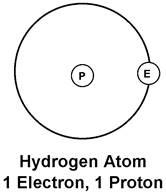
The simplest atom of all - the Hydrogen atom, consists of a single electron orbiting a nucleus, which, is composed of a single proton.
Figure 1a – The Hydrogen Atom
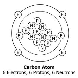
The carbon atom consists of, 6 electrons orbiting a nucleus of 6 protons and 6 neutrons.
Figure 1b – The Carbon Atom
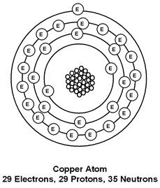
The copper atom consists of, 29 electrons orbiting a nucleus of 29 protons and 35 neutrons.
Figure 1c – The Copper Atom
Electrons orbit the nucleus of the atom in shells. The inner shell cannot have any more than two electrons. The copper atom has four shells. The outer shell is known as the valence shell. The electrons in the outer shell are more easily dislodged from the atom than the electrons in the inner shells. An atom cannot have more than eight electrons in its outer or valence shell.
There are basic laws of nature, which describes the action of electric charges. These laws state:
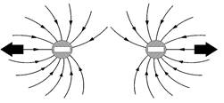
Figures 2a, 2b and 2c illustrate how negative and positive charges behave in relation to each other.
Figure 2a – Two negative electrons repel
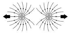
Figure 2b – Two positive protons repel
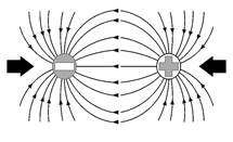
Figure 2c – An electron and a proton attract
In the previously mentioned examples (hydrogen, carbon and copper ) you may have noticed that the number of electrons was always equal to the number of protons. This is normally true of any atom. When this is the case, the atom is said to be neutral, balanced or normal. However, external forces can upset this state.
An atom that has gained or lost one or more electrons is no longer balanced. An unbalanced atom is called an ion. The atom that has lost an electron has an overall Positive charge. The atom that has gained an electron has an overall Negative charge.
In some materials the electrons in the outer shells are easily dislodged. They can move from atom to atom inside the material. This movement of electrons is electric current flow. Materials, through which electric current can flow freely, are called conductors. Some typical conductors are copper, aluminium, brass, steel, silver and gold.
In other materials the electrons are tightly bound to their own particular atoms. Electric current cannot flow freely through them. These materials are known as insulators. Some typical insulators are (Poly-Vinyl Chloride), PVC, rubber, plastic, glass, porcelain and magnesium oxide.
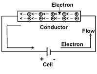
Electric current is the movement of free electrons. These electrons have a negative charge and are attracted to a positive charge. When the terminals of a cell are connected via a conductor as shown in Figure 3, free electrons drift purposefully in one direction only. This flow of current, is known as Direct Current (DC).
Figure 3– Flow of negative electrons from negative to positive
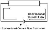
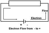
The electrons close to the positive plate of the cell are attracted to it. Each electron that enters the positive plate causes an electron to leave the negative plate and move through the conductor. The number of electrons in the conductor remains constant. The movement of electrons through a conductor is from negative to positive. Long before this theory was discovered, it was thought that current flowed from positive to negative. This direction of current flow is called conventional current flow. Figure 4 below illustrates the difference between the flow of electrons and the flow of conventional current.
Figure 4– Difference between the flow of electrons and the flow of conventional current
This movement of electrons through a conductor is known as an electric current and is measured in Amperes.
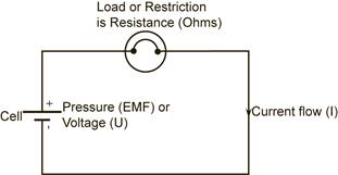
For continuous current flow, there must be a complete circuit. If the circuit is broken, by opening a switch for example, electron movement and therefore the current will stop immediately. To cause a current to flow through a circuit, a driving force is required, just as a circulating pump is required to drive water around a central heating system. Figure 5 below illustrates a conventional liquid circuit.
Figure 5– Conventional liquid circuit
This driving force is the electromotive force (abbreviated to EMF). It is the energy, which causes current to flow through a circuit. Each time an electron passes through the source of EMF, more energy is provided to keep it moving. See Figure 5 below which has the main components for a typical electrical circuit.
Figure 5– Conventional electrical circuit
The source of supply will provide pressure called Electromotive Force or Voltage. The symbol for voltage is U.
The simplest analogy of an electric circuit is to consider a hosepipe connected to a tap. The rate of flow of water from the end of the hosepipe will depend upon:
If there are many restrictions, the water will flow out of the hosepipe at a reduced rate.
Figure 6– Water circuit as an analogy for an electrical circuit
In much the same way, current flows through conductors by means of electric pressure provided by a battery or generating source. This source of electric pressure, electromotive force (EMF ), provides the energy required to push current through the circuit. It can be referred to as the supply voltage.
Every circuit offers some opposition or restriction to current flow, which is called circuit resistance. The unit of resistance is the Ohm, symbol W, pronounced Omega. At this stage, conductor resistance is ignored and the load resistance is treated as the total opposition to current flow.
For a stable supply voltage, the current (I) which flows, is determined by resistance (R) of the circuit. There will be a voltage drop across different parts of the circuit and this is called Potential Difference (PD).
Figure 7–electrical circuit
Unlike the hosepipe analogy, the electric circuit requires a “go” and “return” conductor to form a closed loop or complete circuit. These conductors must offer a low resistance path to the flow of current. Most metallic conductors satisfy this requirement.
George Ohm discovered the relationship between, current flowing in a circuit and the pressure applied across that circuit. This became known as Ohm’s Law.
Ohm’s Law states that the current (I) flowing through a circuit is directly proportional to the potential difference (U), across that circuit, and inversely proportional to the resistance (R), of that circuit, provided the temperature remains constant.
When an electric current flows in a circuit it can have one or more of the following effects:
The movement of electrons in a circuit, which is the flow of an electric current, causes an increase in the temperature of the load resistance. The huge number of electrons being pushed through the load resistance, results in high friction and collision of these electrons. This generates heat. The amount of heat generated depends upon the type and dimensions of the load resistance wire and the value of current flowing. By changing these variables, a length of resistance wire may be operated at different temperatures to give different effects, e.g. an ordinary light bulb or an electric heater.

Figure 8–The heating effect of electrical current
Whenever a current flows in a conductor a magnetic field is set up around that conductor.
Figure 9–The magnetic effect of electrical current
This magnetic field increases in strength if the current is increased and collapses if the current is switched off. A “current carrying conductor”, wound in the form of a solenoid ( coil ), produces a magnetic field very similar to that of a permanent magnet, but has the advantage in that it can be switched on or off by any switch controlling the circuit current. The magnetic effect of an electric current is the principle upon which electric bells, relays, moving coil instruments, motors and generators work.
When an electric current flows through an electrolyte (conducting liquid / paste), this electrolyte is separated into chemical parts. The two conductors, which make contact with the electrolyte, are called the anode (positive plate) and the cathode (negative plate). An anode or cathode of dissimilar metals placed in an electrolyte can react chemically and produce an EMF. When a load is connected across the anode and cathode, a current will flow in the circuit. The chemical effect of an electric current is the principle upon which electric battery operates.
Figure 10–The chemical effect of electrical current
Electricity is widely recognized as a potential workplace hazard, exposing employees to electric shock, burns, fires and explosions. Working on or around electrical conductors and equipment can be particularly dangerous, because electrical energy often cannot be sensed until contact is made. The following guidelines should be applied to every workday:
On a daily basis, before starting any task, inspect the work area for possible electrical hazards. Take all necessary precautions to avoid cutting into electrical lines. In work areas where the exact location of the electrical power is unknown, power in the general vicinity of the building should be de-energized.
Operators should wear proper dielectric safety footwear and rubber insulating gloves. Instruct each employee on how to recognize and avoid unsafe conditions that apply to the work areas.
Shut off the main power source when working on anything electrical, such as switches and outlets. Follow lockout/tagout procedures. Never overload a circuit by plugging too many items into one outlet.
Assure proper grounding of all electrical equipment. Use equipment that provides a permanent and continuous path from circuits, equipment, structures, conduit or enclosures to ground and ensure that proper safety trip switches are fitted.
If working near high voltage lines, operators must maintain a safe working distance—a minimum distance of 3 meters (50 kV line or less) between their equipment and the electrical distribution or transmission lines. The higher the voltage line, the greater the distance that is required between the equipment and the line.
Only use 110V power tools and extension cables on site. If exceptional circumstances require the use of 220V equipment or cables then these should be armoured cables and use correct industrial safety plugs and sockets.
Inspect electrical tools and equipment daily. Remove defective or suspect equipment from use and tag “Do Not Use.” Make sure equipment is properly maintained.
Do not use worn or frayed electrical cords or any electrical cord with visible wires. Verify the ground plug is present and has not been damaged or modified.
Keep all cables and cords out of the path of travel and away from saw blades, core bits, air tools and keep them from being run over by equipment. Electrical cables in high traffic areas should be protected. Electrical cables should not be secured with staples, coat hangers, nails or wire. Keep all cables, tools and electrical connections dry.
Ensure all components, cables, plugs and twist locks are properly sized and not modified from their original specifications. If a cable is warm or hot to the touch, the cable is too small for the equipment being used. Use cables that are rated to carry the maximum current ratings of the motor being used. Larger cords are necessary when using longer stretches of cord.
Make sure that power tools are switched OFF before plugging them in. Shut off power whenever possible when connecting or disconnecting connectors. Verify that once connected, the cable is fully plugged in, secured and cannot be disconnected.
Do not pick up or carry a tool by its cord or hose. Do not unplug by pulling on the cable. Grasp plug body to remove or insert a cable from an outlet and never use excessive force.
Develop and maintain a safety and health program to provide guidance for safe operations. Proper maintenance and records will help ensure that all equipment is safe.
Identify the Hazard |
Identify the risk |
Action to minimise the risk |
|
|
|
|
|
|
|
|
|
|
|
|
|
|
|
|
|
|
|
|
|
If equipment operating at 230 volts or higher is used, an RCD (residual current device) can provide additional safety. An RCD is a device which detects some, but not all, faults in the electrical system and rapidly switches off the supply. The best place for an RCD is built into the main switchboard or the socket-outlet, as this means that the supply cables are permanently protected. If this is not possible a plug incorporating an RCD, or a plug-in RCD adaptor, can also provide additional safety.
RCDs for protecting people have a rated tripping current (sensitivity) of not more than 30 milliamps (mA). Remember:
An RCD is a valuable safety device, never bypass it;
If the RCD trips, it is a sign there is a fault. Check the system before using it again;
If the RCD trips frequently and no fault can be found in the system, consult the manufacturer of the RCD;
The RCD has a test button to check that its mechanism is free and functioning. Use this regularly.
One of the most fundamental rules of electrical safety is to recognise that all cables are potentially live until verified otherwise. Personnel should treat all electrical circuits as "Live" until they have been tested tagged and locked out by a competent certified electrician. Conduct any work on the circuit only after determining that there is no voltage in any of the exposed circuits. If voltage is detected in any exposed circuit, STOP, inform supervisor and determine source and procedure to eliminate voltage.
There are 3 main levels of voltage used for electrical equipment on sites, 110 volt power, 220 volt power and 440 volt or 3 phase power.
On a 110V system there is one positive wire a neutral wire and a ground. With a 220V there are 2 positive wires (hot wires) and a ground 220V is double volts compared to a 110V system. After 220V next is called 440V also known as a three phase supply. 110V is what most small power tools use and 220V is used for larger equipment such as welders or hot water heaters.
The reason for the two voltages is that some equipment, such as welders or a water heater, draws a lot of power. A water heater is typically 4400 watts. At 110V this would be 40 amps. That would take a wire of a large cross sectional area. At 220V, 4400 watts only takes 20 amps. You don't need as big a wire for the same power. The lower current is also a little safer as the potential heating in the wiring is reduced. This is also why most 110V AC appliances are limited to about 1200 to 1500 watts. 1200 watts on a 110V AC circuit is just under 11 amps. 1500 watts is just over 13.5 amps. Most domestic homes have 20 amp circuit breakers but older houses may have 15 amp breakers or fuses
Giving a device a lower voltage than it was designed for is generally not dangerous; the device may not work correctly, but no dramatic failure is likely. Giving any device a voltage higher than it was designed for is dangerous and will very likely damage the device. If you put 230 volts into a device designed for 110 it may melt, catch fire, or even explode.
Location of underground services and cables is necessary because drawings often lack the pinpoint precision needed to ensure proper clearance for site excavations. Because many different types of materials go into manufacturing the different types of underground lines and services, different detection and location methods must be used. For metal pipes and cables, this is often done with electromagnetic equipment consisting of a transmitter and a receiver. For other types of pipe, such as plastic or concrete, other types of radiolocation or modern ground-penetrating radar must be used.
![]()
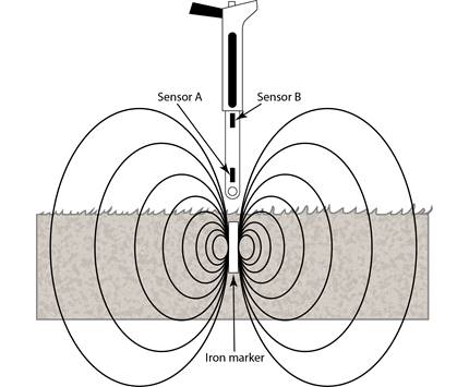
Underground cables can be pinpointed using a electromagnetic instrument as illustrated in figure 11 which can often provide depth and current readings based on electromagnetic signals that radiate from the buried cable.
Figure 11–Cable locating device
Electromagnetic locators detect the magnetic field of ferromagnetic objects. They respond to the difference in the magnetic field between two sensors that are spaced approximately 250mm apart. Some devices use only an audio tone which gets louder as you get closer while others also have a visual display which shows the signal polarity and a bar graph to help determine the targets orientation.
Injuries resulting from damage to live electricity cables are usually caused by the explosive effects of arcing current, and by any associated fire or flames which may follow, when the sheath of a cable and the conductor insulation is penetrated by a sharp object such as the point of a tool. One of the main dangers which may arise when digging is that of possible injury from underground power cables. You should not commence any excavation until you have taken at minimum the following precautions:
People are killed and injured each year by accidental contact or near contact with overhead electricity lines. Most of these accidents occur when there is contact or near contact with overhead lines by cranes or excavators, by tipping trucks or truck mounted cranes, by mobile extendable machinery, or by metal equipment such as scaffolding, metal gutters, long metal handled concrete floats or metal ladders. Such accidents can be prevented by taking all practicable precautions to prevent accidental contact or near contact - which may cause electrical arcing from the overhead line.
Figure 12–Hazard from overhead cables and the method employed to eliminate the risk
When working in the vicinity of overhead power lines the following safety guidelines should be observed:
Armoured cables, as the name suggest are the type of cables covered with a lot of protection. These armoured cables are covered with strong steel strands wrapped round the cable. They are usually used for transferring power either underground or overhead. Armoured cables are mostly used for burial wiring because the ordinary mains cable may be damaged by the hit of a spade or other sharp tools.
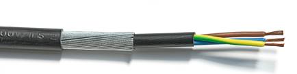
Figure 13–Structure of Armoured cable
Figure 13 shows the structure of armoured cable, the armoured cable is constructed of three layers of protection. The innermost core is generally multi strand and each one is individually sheathed from each other. There may be two, three, or four strands depending upon the application. Then an overall plastic sheath covers these individual strands altogether in a single unit. Further it is covered by protective wire armour. Finally there is an outer sheath to hold it. The three core cable - live, neutral and earth - is mostly used in domestic installations while the four core cable is used when there is a three phase supply is in use.
Power tools can be hazardous when improperly used. There are several types of power tools, based on the power source they use: electric, pneumatic, liquid fuel, hydraulic, and powder-actuated. Employees should be trained in the use of all tools - not just power tools. They should understand the potential hazards as well as the safety precautions to prevent those hazards from occurring. The following general precautions should be observed by power tool users:
Only properly qualified and trained personnel should perform maintenance and electrical safety checks on portable power tools. However any personnel using portable power tools should at a minimum be aware of the following guidelines for safe use and basic maintenance of portable power tools:
The supply of 220V is fatal but a 110V supply is not. On building sites, a 110V power supply is provided using an isolating transformer to provide two 55volt lines out of phase. That means you can connect 110V equipment across them. If someone were to cut through the cable by accident, the worst shock they will get is 55volts which is very unlikely to be fatal.
The physical differences are the gauge of the cable and the number of windings on the motor. 220V equipment plugged into a 110V supply will run off load at roughly quarter speed and is likely to stall on load. 110V equipment plugged into a 220V supply tends to burn out.
Where possible power tools should be plugged directly into wall sockets to minimize or eliminate the risks associated with extension cables. Where this is not possible the following guidelines should be observed when using extension cables.
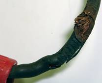
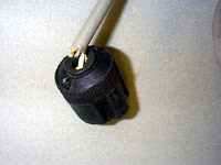
Figure 14–Frayed cables and strained cables caused by inappropriate use
Title |
Author |
Ref. Code |
The Induction Book, “Code of Behaviour & Health & Safety Guidelines” |
SOLAS |
|
Basic Welding and Fabrication |
W Kenyon |
ISBN 0-582-00536-L |
Fundamentals of Fabrication and Welding Engineering |
FJM Smith |
ISBN 0-582-09799-1 |
Workshop processes, practices and materials, 3rd edition, Elsevier Science & Technology |
Black, Bruce J 2004 |
ISBN-13: 9780750660730 |
New Engineering Technology |
Lawrence Smyth & Liam Hennessy |
ISBN 086 1674480 |
Source: http://local.ecollege.ie/Content/APPRENTICE/liu/pipefitting/word/M4_U3_Electricity%20On%20Site.doc
Web site to visit: http://local.ecollege.ie/
Author of the text: indicated on the source document of the above text
If you are the author of the text above and you not agree to share your knowledge for teaching, research, scholarship (for fair use as indicated in the United States copyrigh low) please send us an e-mail and we will remove your text quickly. Fair use is a limitation and exception to the exclusive right granted by copyright law to the author of a creative work. In United States copyright law, fair use is a doctrine that permits limited use of copyrighted material without acquiring permission from the rights holders. Examples of fair use include commentary, search engines, criticism, news reporting, research, teaching, library archiving and scholarship. It provides for the legal, unlicensed citation or incorporation of copyrighted material in another author's work under a four-factor balancing test. (source: http://en.wikipedia.org/wiki/Fair_use)
The information of medicine and health contained in the site are of a general nature and purpose which is purely informative and for this reason may not replace in any case, the council of a doctor or a qualified entity legally to the profession.
The texts are the property of their respective authors and we thank them for giving us the opportunity to share for free to students, teachers and users of the Web their texts will used only for illustrative educational and scientific purposes only.
All the information in our site are given for nonprofit educational purposes