
ME317 Design for Manufacturing
Lecture 06: Forging of Metals
Forging: a process in which the workpiece is shaped by compressive forces applied through the use of dies and tools.
Using an anvil and a hammer is a crude form of forging.
Characteristics of forging:
-- usually involves discrete parts
-- may be done on hot or cold materials
-- often requires additional finishing processes, such as heat treating,
machining, or cleaning.
-- may be done at fast or slow deformation rates
-- may be used on very small or very large parts
-- generally improves the physical properties of a part by controlling
and refining the flow or grain of the material.
Materials: most metals and alloys may be shaped by forging by use of proper lubricant and temperature. Forgeable materials include:
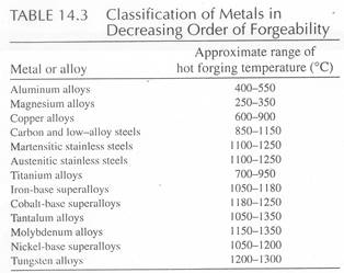
from http://www.forging.org
Table-1 Common Applications for Forgings |
|
|
|
|
|
Terms and Definitions:
Thickness-- the amount of material confined between two parallel surfaces, and measured normal to the surfaces.
Web--thin panel member usually parallel to the plan view of forging.
Wall--members that create the periphery of the forging and are usually perpendicular to webs.
Rib--thin gusset type internal members usually perpendicular to the web.
Boss--a relatively short protrusion or projection on the surface of a forging, often cylindrical in shape.
Flash Extension--excess material remaining on a forging after normal trimming, usually present at all parting line locations.
Match--the alignment of feature on a forged part formed by opposing segments of a die.
Draft--a taper applied to selected surfaces of a forged part to aid its removal from the die Draft normally is larger on internal surfaces, and smaller on external surfaces, where features are formed by more than one piece of the die.
No-draft--refers to external surfaces on forgings that are free of draft but are controlled by the implied angular tolerance of ±0 degree 30 minutes. This usually is specified in the drawing title block.
Parting Line--the location on the forging where excess material in the form of flash is allowed to exit from the forging during the forging operation.
Seam Line-- a line that may be visible on finished precision forgings, indicates a junction of mating die components in segmented die construction.
Plan View Area--the surface area that the press must apply pressure to; it is express in square inches.
Forging Direction--the direction in which the forging press is applying pressure to produce the part.
Die Closure--refers to the function of the closing together of the upper and lower members of a forge die during the process of actually producing a forging. The features of the forging that will be affected by die closure will be all web thicknesses and wall heights.
Types of Forging Processes:
Open-Die Forging-- forging in which the dies are relatively flat and allow the material to freely deform in directions lateral to the applied load.
-- Upsetting
-- Cogging
-- Fullering
-- Edging
-- Heading
-- Piercing
Impression Die Forging
Closed-Die Forging
-- Cold Extrusion
Other special methods:
-- Roll Forging
-- Hubbing
-- Orbital Forging
-- Swaging or Radial Forging
More Details:
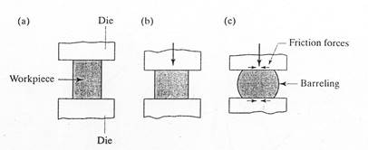
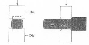
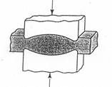
Open Die Forging: forging in which the dies are relatively flat and allow the material to freely deform in directions lateral to the applied load.
-- Upsetting: forging performed between two flat dies.
-- Cogging (or drawing out): forging that occurs when the deformation is done in by successive steps at specific intervals systematically over a larger piece.
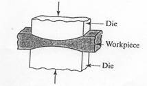
--Fullering: forging with an angled die that moves material laterally toward the center of the load.
-- Edging: forging with an angled die that moves material laterally away from the load center.
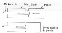
-- Heading: an upsetting process used to
create head bolts, screws or other fasteners.
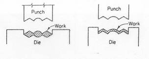
-- Piercing: forging used to make impressions or holes in a workpiece.
-- usually required a number of
intermediate forging and
trimming steps to fully form
the workpiece.
--requires more complex
(and more expensive) dies
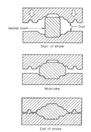
Closed-Die Forging: forging in which the material is fullly constrained in the cavity created by the upper and lower die halves.
-- allows more accurately shaped parts to be formed.
-- no flash is formed, therefore no waste material
-- higher interface pressures required
-- requires very accurate control of material volume and proper die design.
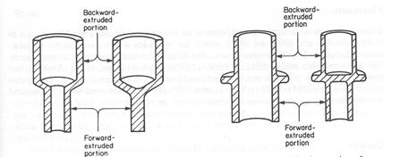
-- Cold Extrusion—a closed-die forging process where material moves in forward and/or reverse direction more than laterally.

-- Precision Forging: a name given to closed die forming with part of highly controlled accuracy.
--Coining: A closed die forging process used in the minting of coins, medals, and jewelry, in which lubricants are not used and high surface quality and detail is obtained.
Other specialized forging practices:
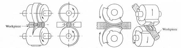
--Roll Forging (or Rolling): forging that is done by using a pair of rollers with shaped grooves.
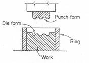
--Hubbing: consists of pressing a hardened punch, with a particular tip geometry, into the a metal's surface…more of a surface treatment.
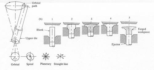
-- Orbital Forging: a process in which the upper die moves along an orbital path and forms the part incrementally. Used to make disk and conical shaped parts.
-- Swaging (or radial forging): subjects a solid rod or tube to radial impact forces by a set of reciprocating dies around a stationary workpiece. This can be used to control both the inside and outside shape of tubular pieces.
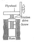
Types of Forging Machines:
Hydraulic Press:Mechanical Press:
- electric powered clutch engaged flywheel
- stroke is applied by eccentric shaft
- force depends on stroke position
- may be used by less skilled operators
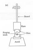
Power Drop Hammers:
- converts potential energy to kinetic
energy
- down stroke is accelerated by steam,
Selection of Forging Machine depends upon:
- force and energy requirements
- material to be forged (soft material use press…hard materials use hammers)
- size, shape and complexity of forging
- strength of the workpiece material
- sensitivity of material to rate of deformation
- production rate
- dimensional accuracy
- maintenance
- operating skill level required
- noise level
- cost
General Design Guidelines:
-- forge parts oversize to allow for additional processing and machining
-- parting lines should be centered, flat, level, and located at the widest
section of the part.
-- avoid or minimize die shapes which set up side-thrust forces.
-- consider material flow lines when designing part and die.
-- lateral material flow is preferred over parallel material flow.
-- include draft angles to facilitate easy part removal.
-- use ribs and bosses which are relatively low , wide, and uniform and taper
these features to facilitate material flow.
-- all external corners (except at parting line) should be rounded with as large a
radius as possible.
-- expect surface finish: 125 to 500 x 10-6 inches
-- typical tolerances: +/- 0.020 inch or 0.3% of the dimension.
3.4.1 A Comparison of Open Die, Impression Die, Rolled Ring and Cold
|
from Product Design Guide for Forging at http://www.forging.org
3.5.4.1 Design Rules for Parts Made From Impression Die Forgings
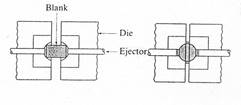
1. All features should be oriented so that they can be formed in impressions moving in opposite directions, such as the part shown in Figure 3-9. Features such as undercuts and holes oriented other than in the direction of forging are not typically forged and must be fully machined. There are, however, a few special presses with side piercing capability, which permit forging of cross-oriented and hollow features.
Figure 3-9 The most economical shape to forge is one that can be formed in impression moving in opposite directions.
2. Forging cost is minimized and tolerances reduced when forging loads are balanced, eliminating side loads on the machine members that restrain the dies. Figures 3.10, 3.11 and 3.12 shows an unbalanced condition and two die alternatives.
3. Sharp exterior corners require high forging pressures to fill the corresponding die features. Sharp interior corners (fillets) cause difficulties in metal flow, and may require one or more preform dies to attain, or may require additional machining operations. Therefore, radii should be as large as possible consistent with functional and assembly constraints. Corner and edge radii should also be uniform to minimize die sinking cost.
4. Interior corner (fillet) radii are dependent on forging severity (primarily rib height) and the forgeability of the alloy. Table 3-2 gives preferred and minimum fillet and corner radii for a 25 mm (1.0 in.) rib height, which corresponds to Part 2 in Figure 3-13.
5. Draft angles should be the maximum allowable, consistent with functional, assembly and weight constraints. For ferrous forgings, draft angles less than 5° usually prohibit the use of hammers. Dies installed in presses are usually equipped with knock-out pins to eject the forging from the cavity, and can produce forgings with little or no draft.
6. As a general rule, less draft is required on the outside of a feature than on the inside. (See Figure 3-14)
Figure 3-12 Where production quantities justify two sets of impression dies, the forgings can be oriented opposite to balance the side loads. This arrangement permits the holes in the bosses to be forged to reduce the amount of machining required.
Figure 3-13 This figure represent shapes that are progressively more difficult to forge.
7. Component features that are held to close tolerances should be formed in the same die member to avoid additional cross-die tolerance.
8. All datum targets and tooling points should be located on features made in the same die half, as illustrated in Figure 3-15. The upper die half is preferred since there is less contact between the die and the forging, and consequently less cooling.
Table 3-2
Representative Fillet and Corner Radii for Forgings with 25 mm (1.0 in.) High Ribs
Alloy |
Fillet Radius mm (in.) |
Corner Radius mm (in.) |
||
Preferred |
Minimum |
Preferred |
Minimum |
|
Carbon Steels |
10-13 (0.375-0.50) |
6 (0.125) |
3 (0.19) |
1.5 (0.06) |
Stainless Steels |
6-13 (0.250-0.50) |
5 (0.19 |
5 (0.19) |
2.5 (0.09) |
Titanium Alloys |
13-16 (0.5-0.62) |
10 (0.38) |
6 (0.25) |
3 (0.12) |
Iron Base Heat |
13-19 (0.5-0.75) |
6-10 (0.25-0.38) |
6 (0.25) |
3 (0.12) |
Figure 3-14 As a general rule, less draft is required on the outside of a feature than on the inside.
from Product Design Guide for Forging at http://www.forging.org
3.5.4.1 Design Rules for Parts Made From Upset Forgings
1. Parts that are symmetrical about an axis are the most economical for upset forging.
2. Upsetting generally increases the diameter of the beginning stock. Therefore, the stock size will generally correspond to the smallest as-forged diameter. This is the case for the flanged member shown in Figure 3-16. However, there are cases in which a nose can be extruded to achieve a smaller diameter.
Figure 3-15 Design so that all datum targets and tooling points are in the same die member, preferably the moving member.
Figure 3-16 The flanged shaft was an ideal candidate for upsetting from bar stock.
3. There are limits to the change in shape that can be achieved in one stroke of an upsetter. There are three rules, which are based on geometric proportions:
Rule 1: The limit of length of unsupported stock that can be gathered in one
upset blow without excessive buckling is not more than three times the
diameter of the bar as shown in Figure 3-17.
Figure 3-17 Rule 1
Rule 2: When the length of unsupported bar stock is more than three times its
diameter, the bar can be upset in one blow provided that the diameter of the
upset is not more than one and one-half times the diameter of the stock as
shown in Figure 3-18.
Figure 3-18 Rule 2
Rule 3: Where the length of unsupported bar stock is more than three times
its diameter, and the diameter of the upset is not more than one and one-
half times the diameter of the stock, the bar can be upset in one blow
provided the amount of unsupported stock beyond the face of the die is not
greater than one and one-half times the diameter of the stock, as shown in
Upset forgings with very large ratios of maximum to minimum diameter, or
with massive features that require gathering sections of bar stock that are
long compared with the diameter, will require several forging operations to
gather the metal and form it to the desired shape while preventing defects.
Figure 3-19 Rule 3
4. Upset forgings with very large ratios of maximum to minimum diameter, or with massive features that require gathering sections of bar stock that are long compared with the diameter, will require several forging operations to gather the metal and form it to the desired shape while preventing defects.
5. Upset dies are essentially three-piece impression dies. Therefore, maximum radii should be used wherever possible to minimize forging pressure and promote die fill.
from Product Design Guide for Forging at http://www.forging.org
3.5.4.3 Design Rules for Parts Made From Open Die Forgings
1. Where material properties are critical, it is important to specify the required properties in all directions. This includes tensile strength, yield strength, ductility and impact toughness. The open die forger will design the forging process to develop grain flow that will optimize the properties. Otherwise the forging will be designed so that the grain flow follows the final contour of the forging.
2. In view of the end use of the product, specify the nondestructive testing methods to be employed and acceptable methods for employing them.
3. Open die forging can be employed for a wide range of shapes. For example, non-symmetrical shapes may be forged. Hollow shells can be forged by combinations of operations such as cogging, upsetting trepanning and punching, then mandrel forging. The ball valve housing shown in Figure 3-20 illustrates the shape capability achievable by open die forging.
Figure 3-20 This ball valve housing illustrates the shape capability of the open die forging process
.
4. Be sure to spell out where any prolongations for testing should be located.
Return to Table of Contents
from Product Design Guide for Forging at http://www.forging.org
3.5.4.4 Design Rules for Parts Made From Rolled Rings
1. To minimize stock allowances, indicate which surfaces may be left as forged.
2. Inside and outside contours are possible where required. See Section 5.2.3 for common contours.
3. Modern ring rolling mills are able to control one of the diameters (either the inside or the outside) more closely than the other. Therefore, indicate the chucking diameter for the first machining operation so that the supplier may produce rings with better consistency in the specified dimension, saving machining setup time.
4. Always specify finish machined dimensions; finish allowances may vary among ring rollers based on individual capabilities. (See Figure 3-21)
5. Supply the drawing, even when purchased quantities are low. Sometimes existing tooling and geometry will fit the requirements.
6. Specify the type and location of required identification, which will be stamped into the ring.
7. Avoid specifying close tolerances and fine surface finish on rough turned rings. Usually a ±1.6 mm (0.062 in.) tolerance and 6.3 micron (250 micro inch) finish are practical.
Source: http://www.rose-hulman.edu/Class/me/ME317/Merkel%20Lectures/ME317Lecture06Forging.doc
Web site to visit: http://www.rose-hulman.edu
Author of the text: indicated on the source document of the above text
If you are the author of the text above and you not agree to share your knowledge for teaching, research, scholarship (for fair use as indicated in the United States copyrigh low) please send us an e-mail and we will remove your text quickly. Fair use is a limitation and exception to the exclusive right granted by copyright law to the author of a creative work. In United States copyright law, fair use is a doctrine that permits limited use of copyrighted material without acquiring permission from the rights holders. Examples of fair use include commentary, search engines, criticism, news reporting, research, teaching, library archiving and scholarship. It provides for the legal, unlicensed citation or incorporation of copyrighted material in another author's work under a four-factor balancing test. (source: http://en.wikipedia.org/wiki/Fair_use)
The information of medicine and health contained in the site are of a general nature and purpose which is purely informative and for this reason may not replace in any case, the council of a doctor or a qualified entity legally to the profession.
The texts are the property of their respective authors and we thank them for giving us the opportunity to share for free to students, teachers and users of the Web their texts will used only for illustrative educational and scientific purposes only.
All the information in our site are given for nonprofit educational purposes