
3.1 Terms
What is form and position tolerances? Form and position tolerances is used to specify the shape, form, orientation, and location of features on a part. Features toleranced with the form and position tolerances reflect the actual relationship between mating parts. Drawings with properly applied geometric tolerance provide the best opportunity for uniform interpretation and cost-effective assembly.
When Should Form and Position Tolerances Be Used?
Many designers ask under what circumstances they should use the form and position tolerances. Because form and position tolerances were designed to position size features, the simplest answer is, locate all size features with form and position tolerances controls. Designers should tolerance parts with the form and position tolerances when
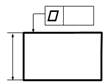
Form Error (shown in Fig.3-1): is the variation of the true form of a single factor to its perfect form make a small shaft found to be distortion and not cylindrical, or the section is out of round, or the axes is bended, or make a plane found to be warp.
Figure 3-1 Examples of Form Error
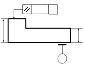
Position Error (shown in Fig.3-2): is the variation of the actual position of related factors to its ideal position form. While machining a stepped shaft, the axial cord of each step may not be the same, namely, concentricity and coaxality error. Surfaces expected to be perpendicular are not perpendicular after it machined.
(a) (b)
Figure 3-2 Examples of Position Error
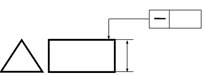
Basic Dimension (shown in Fig.3-3): is a numerical value used to describe theoretically exact characteristics of a feature or datum target.
Figure 3-3 An Example of Basic Dimension
Feature: is a general term applied to a physical portion of a part, such as a surface or a line.
Feature of size : is one cylindrical of spherical surface or a set of parallel surfaces, each of which is associated with a size dimension.
3.2 Characteristic Symbols
Characteristic symbols of form and position tolerances are important not only to know each symbol but also to know how to apply these symbols on drawings. The 14 geometric characteristic symbols
Characteristic Symbols of Form and Position Tolerances
It is important to learn these symbols in their respective categories because many characteristics that apply to one geometric control also apply to other geometric controls in the same category. For example, datums are not appropriate for any of the form controls. Notice that form controls pertain only to individual features. In other words, form controls are not related to datums. Orientation, location, and runout controls must have datums since they are related features. Profile controls may have datums, or not, as required.
3.3 Datums
Datums are the reference surfaces or the starting points for the location and orientation of features. They are essential for appropriate and complete tolerance of a part. Datum geometries can become very complicated when they are features of compound datums or features of an unusual shape. Datums are theoretically perfect points, lines, and planes. They establish the origin from which the location or geometric characteristics of features of a part are established. Datums are specified in the order of precedence as they appear from left to right in the feature control frame. They need not be in alphabetical order. Datum A in Fig. 3-6 is the primary datum, datum B is the secondary datum, and datum C is the tertiary datum because this is the order in which they appear in the feature control frame. The order of precedence of datums is determined by the order in which they appear from left to right in the feature control frame
![]()
Figure 3-6 An Example of Datums
Multiple Datum Features
When more than one datum feature is used to establish a single datum, the datum reference letters and appropriate modifiers are separated by a dash and specified in one compartment of the feature control frame, as shown in Fig. 3-7. Together, the two datum features constitute one composite datum feature axis where datum A is no more important than datum B and datum B is no more important than datum A.
Figure 3-7 Multiple Datum Features A and B are of Equal Value
3.4 Form Tolerances
All form tolerances apply to single, or individual, features. Consequently, form tolerances are independent of all other features. No datums apply to form tolerances. When the size tolerance does not adequately control the form of a feature, a form tolerance may be specified as a refinement. Except for straightness of a median line and of a median plane, all form tolerances are surface controls and are attached to feature surfaces with a leader or, in some cases, an extension line. No cylindrical tolerance zones or material conditions are appropriate for surface controls.
3.4.1 Flatness
Definition
Flatness of a surface is a condition where all line elements of that surface are in one plane. The surface being controlled in Fig. 3-8 must lie between two parallel planes separated by the flatness tolerance of 0.005mm specified in the feature control frame. In addition, the surface must fall within the size tolerance, the two parallel planes 0.020mm apart. The flatness tolerance zone does not need to be parallel to any other surface as indicated in the right side view.
Figure3-8 Flatness

Figure 3-9 Two Flatness Verification Techniques
Inspection
First, the size feature is measured to verify that it falls within the limits of size. Then, flatness verification is achieved by measuring the surface, in all directions, to determine that the variation does not exceed the tolerance in the feature control frame. The measurement of surface variation in Fig. 3-9A is performed with a dial indicator after the surface in question has been adjusted with jackscrews to remove any parallelism error. In Fig. 3-9B, flatness is measured by moving the part over the probe in the surface plate and reading the indicator to determine the flatness error. This is a relatively simple method of measuring flatness; no adjustment is needed. However, specialized equipment is required.
3.4.2 Straightness
Definition
Straightness is a condition where a line element on a surface, a median line, or a line element of a median plane is a straight line. The line elements being controlled in Fig. 3-10 must lie between two parallel lines separated by the straightness tolerance of 0.004mm specified in the feature control frame and parallel to the view in which they are specified—the front view. In addition, the line elements must fall within the size tolerance of 0.020mm.
Figure 3-10 Straightness of a Surface
Inspection
First, the size feature is measured to verify that it falls within the limits of size. Then, straightness verification is achieved by measuring line elements on the surface, parallel to the view in which they are specified, to determine that straightness variation does not exceed the tolerance indicated in the feature control frame. The measurement of surface variation for straightness is performed similar to the measurement for flatness. Straightness of a cylindrical surface is inspected by moving the dial indicator across the surface plate, against the edge of a precision parallel, measuring line elements on the surface parallel to the axis of the cylinder as indicated in Fig.3-11. Each line element is independent of every other line element, and the surface may be readjusted to remove any parallelism error for the measurement of each subsequent line element. There are an infinite number of line elements on any surface. The inspector must measure a sufficient number of line elements to be convinced that all line elements fall within the tolerance specified. Straightness verification of line elements on a flat surface is measured in a similar fashion. Parallelism error must be removed, and each line element is measured parallel to the surface on which the straightness control appears.
Figure 3-11 Inspection of Straightness of a Surface
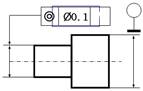
3.4.3 Circularity
Definition
Circularity (roundness) has two definitions, one for a surface of revolution about an axis and the other for a sphere. Circularity is a condition of a surface:
A feature control frame is attached to the surface of the feature with a leader. The leader may be attached to the surface in the circular view of a cylinder, as shown in Fig.3-12, or it may be attached to the surface in the longitudinal view. The feature control frame contains a circularity symbol and a numerical tolerance. Normally, nothing else appears in the feature control frame. Circularity tolerance is a refinement of the size tolerance and must be less than the size tolerance, except for parts subject to free-state variation.
Circular elements in a plane perpendicular to the axis of the part on the surface being controlled must lie between two concentric circles, in which the radial distance between them is equal to the tolerance specified in the feature control frame. Each circular element is independent of every other circular element. That means that the part can look like a stack of pennies that is misaligned and yet can still satisfy a circularity inspection.
Figure 3-12 Circularity Tolerance Applied to a Cylinder and a Taper
Inspection
The feature must first be measured at each cross section to determine that it satisfies the limits of size and the envelop principle. Then, the part is placed on the precision turntable of the circularity inspection machine and centered with the centering screws. The probe contacts the part while it is being rotated on the turntable. The path of the probe is magnified and plotted simultaneously on the polar graph as the part rotates. The circular path plotted on the polar graph in Fig. 3-13 falls within two circular elements on the graph. This particular measurement of the part is circular within a radial distance of 0.002mm.
Figure 3-13 Verification of Circularity with a Circularity Inspection Machine
3.4.4 Cylindricity
Definition
Cylindricity as shown in Fig.3-14 is a condition where all points on the surface of a cylinder are equidistant from the axis. The surface being controlled must lie between two coaxial cylinders in which the radial distance between them is equal to the tolerance specified in the feature control frame. Unlike circularity, the cylindricity tolerance applies to circular and longitudinal elements at the same time. Cylindricity is a composite form tolerance that simultaneously controls circularity, straightness of a surface, and taper of cylindrical features.
Figure 3-14 Cylindricity Tolerance
Inspection
The feature is first measured at each cross section to determine that it satisfies the limits of size. Then, the part is placed on the precision turntable of the circularity inspection machine and centered with the centering screws. The probe contacts the part and moves vertically while the turntable is rotating. The spiral path of the probe is magnified and plotted simultaneously on the polar graph as the part rotates. The spiral path must fall within two concentric cylinders in which the radial distance between them is equal to the tolerance specified in the feature control frame.
3.4.5 Profile
Definition
Profile is a surface control. It is a powerful and versatile tolerance tool. It may be used to control just the size and shape of a feature or the size, shape, orientation, and location of an irregular-shaped feature. The profile tolerance controls the orientation and location of features with unusual shapes, very much like the position tolerance controls the orientation and location of holes or pins. A profile is the outline of an object. Specifically, the profile of a line is the outline of an object in a plane as the plane passes through the object. The profile of a surface is the result of projecting the profile of an object on a plane or taking cross sections through the object at various intervals.
When the leader from a profile tolerance points directly to the profile, the tolerance specified in the feature control frame is equally disposed about the true profile. In Fig. 3-15A, the tolerance of 0.020mm in the feature control frame is evenly divided, 0.010mm outside and 0.010mm inside the true profile. If the leader from a profile tolerance points directly to a segment of a phantom line extending, outside or inside, parallel to the true profile, as shown in Fig. 3-15C and 3-15D, all the tolerance is outside or inside the true profile. The tolerance may even be specified as an unequal bilateral tolerance by drawing segments of phantom lines inside and outside parallel to the profile and specifying the outside tolerance with a basic dimension, as shown in Fig. 3-15B.
Inspection
Inspecting a surface that has been controlled with a profile tolerance can be accomplished in a number of ways. The most common methods of inspecting a profile are listed below:
Figure 3-15 Specifying Profile of a Surface
3.5 Position Tolerances
Position tolerances can be divided into orientation tolerances, and position tolerance, concentricity and symmetry tolerances, and runout tolerance. Orientation tolerances are include parallelism, perpendicularity, and angularity. All orientation controls must have datums. It makes no sense to specify a pin, for instance, to be perpendicular. The pin must be perpendicular to some other feature. The other feature is the datum. Position tolerance is a composite tolerance that controls both the location and the orientation of size features at the same time. It significantly contributes to part function, part interchangeability, optimization of tolerance, and communication of design intent. Both concentricity and symmetry tolerances are reserved for a few unique tolerance applications. The tolerances employ the same tolerance concept but apply to different geometries. Concentricity controls features constructed about an axis, and symmetry controls features constructed about a center plane. Concentricity and symmetry both locate features by controlling their center points within a specified tolerance zone. They are typically used when it is important to accurately balance the mass of a part about its axis or center plane. Runout tolerance is a surface control. It controls surfaces constructed around a datum axis and surfaces constructed perpendicular to a datum axis. Runout tolerance controls several characteristics of surfaces of revolution, such as coaxality and circularity, as that surface is rotated about its datum axis.
3.5.1 Parallelism
Definition
Parallelism is the condition of a surface or center plane, equidistant at all points from a datum plane; also, parallelism is the condition of an axis, equidistant along its length from one or more datum planes or a datum axis. The surface being controlled in Fig. 3-16 must lie between two parallel planes separated by the parallelism tolerance of 0.005mm specified in the feature control frame. The tolerance zone must also be parallel to the datum plane. In addition, the surface must fall within the size tolerance, i.e., the two parallel planes 0.020mm apart. The entire part in Fig.3-16 must fit between two parallel planes 1.020mm apart.
Inspection
Verifying the parallelism of a flat surface is relatively easy. First, the size feature is measured to determine that it falls within the limits of size. Next, the datum surface is placed on top of the surface plate. Then, verification is achieved, as shown in Fig.3-17, by using a dial indicator to measure the surface in all directions to determine that any variation does not exceed the tolerance specified in the feature control frame.
Figure 3-16 Specifying a Plane Surface Parallel to a Plane Surface
Figure 3-17 Verifying Parallelism of a Flat Surface
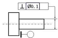
3.5.2 Perpendicularity
Definition
Perpendicularity is the condition of a surface, axis, or center plane that is at a 90◦ angle to a datum plane or datum axis.
In a view where the surface to be controlled appears as a line, a feature control frame is attached to the surface with a leader or extension line, as shown in Fig.3-18. The feature control frame contains a perpendicularity symbol, a numerical tolerance, and at least one datum. The datum feature is identified with a datum feature symbol.
The surface being controlled must lie between two parallel planes separated by the perpendicularity tolerance of 0.010mm specified in the feature control frame. Also, the tolerance zone must be perpendicular to the datum plane. All size features of the part must fall within the limits of size.
Inspection
The datum surface is clamped on an angle plate that sits on a surface plate. Then, as shown in Fig.3-19, perpendicularity verification is achieved by using a dial indicator to measure the surface in all directions to determine that any variation does not exceed the tolerance specified in the feature control frame.
Figure 3-18 Specifying a Plane Surface Perpendicular to a Datum Plane
Figure 3-19 Verifying Perpendicularity of a Flat Surface
3.5.3 Angularity
Definition
Angularity is the condition of a surface, axis, or center plane at a specified angle other than parallel or perpendicular to a datum plane or datum axis. The surface being controlled in Fig.3-20 must lie between two parallel planes separated by the angularity tolerance of 0.010mm specified in the feature control frame. The tolerance zone must be at the specified basic angle of 30◦ to the datum plane.
Inspection
The datum surface may be placed on a sine plate. The sine plate sits on a surface plate at an accurate 30◦ angle produced by a stack of gage blocks. The basic angle between the tolerance zone and datum A is assumed to be perfect. Inspection equipment is not perfect, but inspection instrument error is very small compared to the geometric tolerance. As shown in Fig.3-21, once the datum surface is positioned at the specified angle, angularity verification is achieved by using a dial indicator to measure the surface in all directions to determine that any variation does not exceed the tolerance specified in the feature control frame.
Figure 3-20 Specifying an Angularity Tolerance for a Plane Surface
Figure 3-21 Verification of a Surface at a 30◦ Angle to a Flat Datum Surface
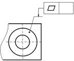
3.5.4 Position
Definition
The position tolerance is a theoretical tolerance zonelocated at true position of the toleranced feature within which the center point, axis, or center plane of the feature may vary from true position.
Since the position tolerance controls only size features, such as pins, holes, tabs, and slots, the feature control frame is always associated with a size dimension. In Fig.3-22, the hole is located and oriented with the position control. In this case, the feature control frame is placed under the local note describing the diameter and size tolerance of the hole. The location of true position of this hole, the theoretically perfect location of the axis, is specified with basic dimensions from the datums indicated in the feature control frame. Once the feature control frame is assigned, an imaginary tolerance zone is defined and located about true position. The datum surfaces have datum feature symbols identifying them. Datums A, B, and C identify the datum reference frame in which the part is to be positioned for processing.
The feature control frame must be specified correctly in order to communicate design intent. The feature control frame in Fig. 3-23 tells the location tolerance story for the hole in this part: it has a cylindrical tolerance zone 0.010mm in diameter, the full length of the feature is perfectly perpendicular to datum plane A, located a basic 2.000 inches up from datum B, and a basic 3.000 inches over from datum C. Tolerance zones are theoretical and do not appear on drawings. A tolerance zone has been shown here for illustration purposes only.
Figure 3-22 Location of a Size Feature with a Position Tolerance
Figure 3-23 The Part is Placed in a Datum Reference Frame
Inspection
Inspection starts with measuring the hole diameter. If the diameter measures 2.012mm, it is within the size tolerance, Ø 2.000–2.020mm. The next step is to measure the hole location and orientation. The part is clamped in a datum reference frame by bringing a minimum of three points on the surface of the primary datum feature into contact with the primary datum plane, a minimum of two points on the surface of the secondary datum feature into contact with the secondary datum plane, and a minimum of one point on the surface of the tertiary datum feature into contact with the third datum plane. Next, the largest pin gage to fit inside the hole is used to simulate the actual mating envelope. The actual mating envelope for an internal feature of size is the largest, similar, perfect feature counterpart that can be inscribed within the feature so that it just contacts the surface of the hole at the highest points. As shown in Fig. 3-24, the distance from the surface plate, datum B, to the top of the pin gage is measured. Measurements are also taken along the pin gage to determine that the hole is within the perpendicularity tolerance to the angle plate, datum A. Suppose the distance from the surface plate to the top of the pin is 3.008mm. That measurement minus half of the diameter of the pin gage equals the distance from datum B to the actual axis of the hole, 3.008 − (2.012/2) = 2.002mm. The distance, then, from true position to the actual axis of the hole in the vertical direction is 0.002mm. With the part still clamped to it, the angle plate is rotated 90◦, and the distance from datum C to the actual axis of the hole is measured by repeating the previous measurement procedure. If the distance from true position to the actual axis in the horizontal direction is 0.002mm, the actual axis is 0.002mm up and 0.002mm over from true position requiring a tolerance zone diameter of less than 0.006mm, well within the 0.010mm diameter cylindrical tolerance zone shown in Fig.3-24. The hole is within tolerance.
Figure 3-24 Inspecting the Hole Location by Using the Theoretical Tolerance Zone
3.5.5 Concentricity
Definition
Concentricity is that condition where the median points of all diametrically opposed points of a surface of revolution are congruent with the axis (or center point) of a datum feature. Concentricity applies to correspondingly located points of two or more radically disposed features, such as the flats on a regular hexagon, or opposing lobes on features such as an ellipse.
Concentricity controls all median points of all diametrically opposed points on the surface of the toleranced feature. The aggregate of all median points, sometimes described as a “cloud of median points,” must lie within a cylindrical tolerance zone whose axis is coincident with the axis of the datum feature. The concentricity tolerance is independent of both size and form. Differential measurement excludes size, shape, and form while controlling the median points of the feature. The feature control frame in Fig. 3-25 specifies a cylindrical tolerance zone 0.005mm in diameter and coaxial with the datum axis. Differential measurements are taken along and around the toleranced feature to determine the location of its median points. If all median points fall inside the tolerance zone, the feature is in tolerance.
Figure 3-25 Concentricity Has a Cylindrical Tolerance Zone
Inspection
Concentricity can be inspected, for acceptance only, by placing a dial indicator on the toleranced surface of revolution and rotating the part about the datum axis as shown in Fig.3-26. If the full indicator movement (FIM) on the dial indicator does not exceed the specified tolerance, the feature is acceptable. This technique is a simple first check that will accept parts but will not reject them, and it can be used only on surfaces of revolution. Features such as regular polygons and ellipses must be inspected using the traditional method of differential measurements. If the measurement does exceed the FIM, the part is not necessarily out of tolerance. To reject a part with a concentricity tolerance, the datum is placed in a chucking device that will rotate the part about its datum axis. A point on the surface of the toleranced feature is measured with a dial indicator. The part is then rotated 180◦ so the diametrically opposed point can be measured. The difference between the measurements of the two points determines the location of the median point. This process is repeated a predetermined number of times. If all median points fall within the tolerance zone, the feature is in tolerance.
Figure 3-26 Inspecting a Part with a Concentricity Tolerance
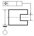
3.5.6 Symmetry
Definition
Symmetry is that condition where the median points of all opposed or correspondingly located points of two or more feature surfaces are congruent with the axis or center plane of a datum feature. It has a tolerance zone that consists of two parallel planes evenly disposed about the center plane or axis of the datum feature. It must have at least one datum. A feature control frame is usually placed beneath the size dimension or attached to an extension of the dimension line. The symmetry tolerance has no relationship to the size of the feature being controlled and may be either larger or smaller than the size tolerance.
As shown in Fig.3-27, symmetry controls the median points of all opposed or correspondingly located points of two or more surfaces. The aggregate of all median points, sometimes described as a “cloud of median points,” must lie within a tolerance zone defined by two parallel planes equally disposed about the center plane of the datum feature, i.e., half of the tolerance is on one side of the center plane, and half is on the other side. The symmetry tolerance is independent of both size and form.
Figure 3-27 Symmetry Tolerance Zone Consists of Two Parallel Planes
The feature control frame in Fig. 3-28 specifies a tolerance zone consisting of two parallel planes 0.010mm apart, perpendicular to datum plane A, and equally disposed about datum plane B. Differential measurements are taken between the two surfaces to determine the location of the median points. If all median points fall inside the tolerance zone, the feature is in tolerance.
Figure 3-28 A Symmetry Tolerance Locating a Symmetrical Feature
Inspection
A simple method of measuring symmetry is shown in Fig.3-29. This method can be used only if the datum surfaces are parallel compared to the symmetry tolerance. In this example, one of the datum surfaces is placed on the surface plate. A dial indicator is used to measure a number of points on the surface of the slot. These measurements are recorded. The part is turned over, and the process is repeated. The measurements are compared to determine the location of the median points and whether or not the feature is in tolerance.
Figure 3-29 Inspecting a Part with a Symmetry Tolerance
3.5.7 Runout
Definition
Runout is a composite tolerance used to control the functional relationship of one or more features of a part to a datum axis. It can be divided into circular runout and total runout.
Circular Runout
Circular runout applies to every circular element on the surface of a part constructed either around its datum axis or perpendicular to its datum axis, while the part is rotated 360◦ about that datum axis. as shown in Fig.3-30, circular runout tolerance applies independently to each circular line element at each measurement position and may easily be applied to cones and curved profiles constructed around a datum axis. Where applied to surfaces constructed around a datum axis, circular runout controls a combination of variations in circularity and coaxality. Where applied to surfaces at a 90◦ angle to a datum axis, circular runout controls variations in perpendicularity of circular elements to its datum axis, that is, total runout controls wobble.
Figure 3-30 Circular Runout
Total Runout
As shown in Fig.3-31, total runout is a compound control that applies to all elements on the surface of a part either around its datum axis or perpendicular to its datum axis, as the part is rotated 360◦ about that datum axis. Total runout tolerance applies simultaneously to all circular and profile measurement positions. Where applied to surfaces constructed around a datum axis, total runout controls a combination of coaxality, circularity, straightness, angularity, taper, and profile variations of the surface. Where applied to surfaces at a 90◦ angle to a datum axis, total runout controls the combination of variations of perpendicularity to the datum axis and flatness, i.e., total runout controls wobble and concavity or convexity.
When specifying runout, the feature control frame is connected to the controlled surface with a leader. In some infrequent instances, the feature control frame may be attached to the extension of a dimension line if the surface to be controlled is small or inaccessible. The feature control frame consists of a runout symbol, the numerical tolerance, and at least one datum. No other symbols are appropriate in the feature control frame. Where runout is required for only a portion of a surface, a thick chain line is drawn on one side adjacent to the profile of the surface and dimensioned with a basic dimension as shown in Fig. 3-32.
Figure 3-31 Total Runout
Figure 3-32 Specifying Runout
Inspecting
As shown in Fig.3-33, when inspecting circular runout, the feature, first, must fall within the specified size limits. The datum feature is then mounted in a chuck or a collet. With a dial indicator contacting the surface to be inspected, the part is rotated 360◦ about its simulated datum axis. Several measuring positions are inspected. If the full indicator movement (FIM) does not exceed the specified runout tolerance, the feature is acceptable. Runout tolerance may be larger than the size tolerance. If the runout tolerance is larger than the size tolerance and no other geometric tolerance is applied, the size tolerance controls the form. If the size tolerance is larger than the runout tolerance, circular runout refines circularity as well as controls coaxiality.
The same preliminary checks required for circular runout are also required for total runout. Just as when inspecting circular runout, a dial indicator contacts the surface to be inspected, but the dial indicator is moved along the full length of the feature’s profile as the part is rotated 360◦ about its simulated datum axis. If the FIM does not exceed the specified runout tolerance, the feature is acceptable.
Figure 3-33 Inspecting Circular Runout Relative to a Datum Axis
3.6 Marking Method
Tolerance Code
The code of the form and position tolerances is represented by the form and position frames
Reference Code
The reference code is made up of the capital letter with a small circle connected by fine lines and short thick lines as shown in Fig.3-35. In order to avoid misunderstanding, generally, E、I、J、M、O、P and such letters are not adopted. The letter of the datum shall be marked in the tolerance frame no matter how the direction of the datum on the drawing varies. Its letter inside the circle shall be printed vertically.
Method of Marking Geometrical Tolerances
1. As shown in Fig.3-36, if the element being tested with a tolerance requirement is a contour line or surface, point the arrow and datum symbol to the contour line or surface, and keep it away from the dimension line.
(a) (b) (c)
Figure 3-36 Marking Method
2. As shown in Fig.3-37, if the element being tested with tolerance requirements is an axis, centre line or symmetrical plane, the arrow and datum symbol should be aligned to the dimension line of that element.
(a) (b) (c)
Figure 3-37 Marking Method
3. As shown in Fig.3-38, if the element being tested is a surface on the drawing, one can draw a reference line with a dot end and point the arrow or datum symbol to the reference line.
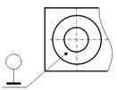
(a) (b)
Figure 3-38 Marking Method
Modifying Symbols
Source: http://ime.djtu.edu.cn/upload/pictures201011/101118131153bb17faa332595b31.doc
Web site to visit: http://ime.djtu.edu.cn/
Author of the text: indicated on the source document of the above text
If you are the author of the text above and you not agree to share your knowledge for teaching, research, scholarship (for fair use as indicated in the United States copyrigh low) please send us an e-mail and we will remove your text quickly. Fair use is a limitation and exception to the exclusive right granted by copyright law to the author of a creative work. In United States copyright law, fair use is a doctrine that permits limited use of copyrighted material without acquiring permission from the rights holders. Examples of fair use include commentary, search engines, criticism, news reporting, research, teaching, library archiving and scholarship. It provides for the legal, unlicensed citation or incorporation of copyrighted material in another author's work under a four-factor balancing test. (source: http://en.wikipedia.org/wiki/Fair_use)
The information of medicine and health contained in the site are of a general nature and purpose which is purely informative and for this reason may not replace in any case, the council of a doctor or a qualified entity legally to the profession.
The texts are the property of their respective authors and we thank them for giving us the opportunity to share for free to students, teachers and users of the Web their texts will used only for illustrative educational and scientific purposes only.
All the information in our site are given for nonprofit educational purposes