
Students will often experience difficulty in handling problems involving two and three-dimensional geometrical constructions.
Copying a selection of these examples on the drawing board or on CAD equipment will certainly enable the reader to gain confidence. It will assist them to visualise and position the lines in space, which form each part of a view, or the boundary, of a three-dimensional object. It is a necessary part of draughtsmanship to be able to justify every line and dimension which appears on a drawing correctly.
Many software programs will offer facilities to perform a range of constructions, for example tangents, ellipses and irregular curves. Use these features where possible in the examples that follow.
Assume all basic dimensions where applicable.
Figure 1
Figure 2
Figure 3
Figure 4
Figure 5
Figure 6
Method A
Figure 7
Method B
Figure 8
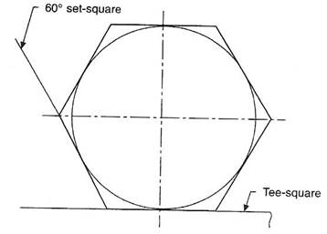
Figure 9
Repeat the instructions in Figure 8 but use a 45° set-square, then connect the eight points to give the required octagon.
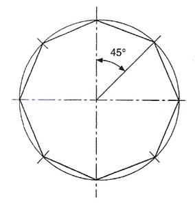
Figure 10
Repeat the instructions in Figure 9 but use a 45° set-square to give the required octagon.
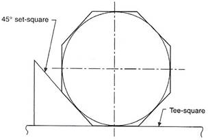
Figure 11
Note that a regular polygon is defined as a plane figure which is bounded by straight lines of equal length and which contains angles of equal size. Assume the number of sides is seven in this example.
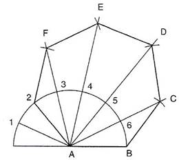
Figure 12
If a disc stands on its edge on a flat surface it will touch the surface at one point. This point is known as the point of tangency, as shown in Figure 13 and the straight line which represents the flat plane is known as a tangent. A line drawn from the point of tangency to the centre of the disc is called a normal, and the tangent makes an angle of 90° with the normal.
The following constructions show the methods of drawing tangents in various circumstances.
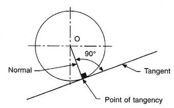
Figure 13
Join OA and extend the line for a short distance. Erect a perpendicular at point A by the method shown.
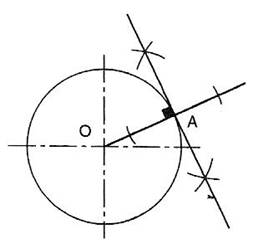
Figure 14
Join A to the centre of the circle O. Bisect line AO so that point B is the mid-point of AO. With centre B, draw a semi-circle to intersect the given circle at point e. Line AC is the required tangent.
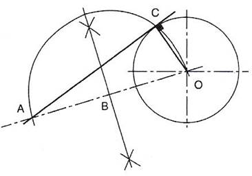
Figure 15
Join the centres of the circles by line AB, bisect AB, and draw a semi-circle. Position point E so that DE is equal to the radius of the smaller circle. Draw radius AE to cut the semi-circle at point G. Draw line AGH so that H lies on the circumference of the larger circle. Note that angle AGB lies in a semi-circle and will be 90°. Draw line HJ parallel to BG. Line HJ will be tangential to the two circles and lines BJ and AGH are the normals.
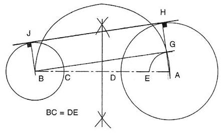
Figure 16
Join the centres of the circles by line AB, bisect AB and draw a semi-circle. Position point E so that DE is equal to the radius of the smaller circle BC. Draw radius AE to cut the semi-circle in H. Join AH; this line crosses the larger circle circumference at J. Draw line BH. From J draw a line parallel to SH to touch the smaller circle at K. Line JK is the required tangent. Note that angle AHB lies in a semi-circle and will therefore be 90°. AJ and BK are normals.
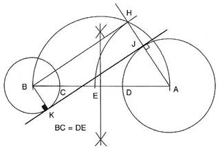
Figure 17
Join the centres of both circles by line AB. Erect perpendiculars at points A and B to touch the circumferences of the circles at points C and D. Line CD will be the external tangent. Bisect line AB to give point E, then bisect BE to give point G. With radius BG, describe a semi-circle to cut the circumference of one of the given circles at H. Join HE and extend it to touch the circumference of the other circle at J. Line HEJ is the required tangent. Note that again the angle in the semi-circle, BHE, will be 90°, and hence BH and AJ are normals.
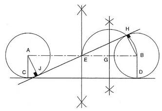
Figure 18
Assume that the radii of the given circles are 20 and 25 mm, spaced 85 mm apart, and that the radius to touch them is 40 mm.
With centre A. describe an arc equal to 20 + 40 = 60 mm.
With centre B, describe an arc equal to 25 + 40 = 65 mm.
The above arcs intersect at point C. With a radius of 40 mm, describe an arc from point C as shown, and note that the points of tangency between the arcs lie along the lines joining the centres AC and BC. It is particularly important to note the position of the points of tangency before lining in engineering drawings, so that the exact length of an arc can be established.
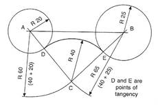
Figure 19
Assume that the radii of the given circles are 22 and 26 mm, spaced 86 mm apart, and that the radius to touch them is 100 mm.
With centre A, describe an arc equal to 100 - 22 = 78mm.
With centre B, describe an arc equal to 100 - 26 = 74mm.
The above arcs intersect at point C. With a radius of 100 mm, describe an arc from point C, and note that in this case the points of tangency lie along line CA extended to D and along line CB extended to E.
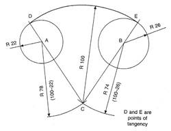
Figure 20
Assume that the radius of the given circle is 20 mm and that the joining radius is 22 mm.
With centre A, describe an arc equal to 20 + 22 = 42mm.
Draw a line parallel to the given straight line and at a perpendicular distance of 22 mm from it, to intersect the arc at point B.
With centre B, describe the required radius of 22 mm, and note that one point of tangency lies on the line AB at C; the other lies at point D such that BD is at 90° to the straight line.
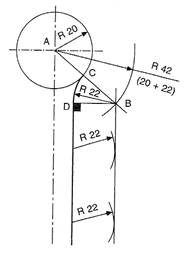
Figure 21
Assume that a radius of 25 mm is required to touch the lines shown in the figures. Draw lines parallel to the given straight lines and at a perpendicular distance of 25 mm from them to intersect at points A. As above, note that the points of tangency are obtained by drawing perpendiculars through the point A to the straight lines in each case.
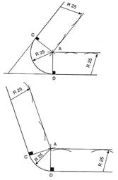
Figure 22
Source: http://local.ecollege.ie/Content/APPRENTICE/liu/metalfab_notes/module6/Tangency_M6_U4.doc
Web site to visit: http://local.ecollege.ie/
Author of the text: indicated on the source document of the above text
If you are the author of the text above and you not agree to share your knowledge for teaching, research, scholarship (for fair use as indicated in the United States copyrigh low) please send us an e-mail and we will remove your text quickly. Fair use is a limitation and exception to the exclusive right granted by copyright law to the author of a creative work. In United States copyright law, fair use is a doctrine that permits limited use of copyrighted material without acquiring permission from the rights holders. Examples of fair use include commentary, search engines, criticism, news reporting, research, teaching, library archiving and scholarship. It provides for the legal, unlicensed citation or incorporation of copyrighted material in another author's work under a four-factor balancing test. (source: http://en.wikipedia.org/wiki/Fair_use)
The information of medicine and health contained in the site are of a general nature and purpose which is purely informative and for this reason may not replace in any case, the council of a doctor or a qualified entity legally to the profession.
The texts are the property of their respective authors and we thank them for giving us the opportunity to share for free to students, teachers and users of the Web their texts will used only for illustrative educational and scientific purposes only.
All the information in our site are given for nonprofit educational purposes