Introduction
The development of the MIG/MAG processes is in some ways a logical progression from the manual metal arc and TIG processes. The effort throughout has been to obtain and maintain maximum versatility, weld quality, speed of deposition simplification of the welding operation and low operation costs.
MIG/MAG welding has been adapted for many industrial applications, and over the past years has become widely used for car body repairs. The method of welding is an electric arc process using DC current and a continuous consumable wire electrode without the addition of flux. On account of the absence of flux, gas is used to shield the arc and weld pool from atmospheric contamination. The process can utilise argon, argon/carbon dioxide mixture or carbon dioxide as the shielding gas, the choice being dependent upon the type of material being welded and the economics associated with selected gas. If non-ferrous metals or stainless steels are to be welded, argon is the usual choice for shielding gas on grounds of compatibility. However when mild steel, low-alloy steels or high-strength steels are to be welded, argon/carbon-dioxide mixture or carbon dioxide is generally used for reasons of overall efficiency weld quality and economy.
Many types and grades of metal can be welded using this method: aluminium, aluminium alloys, carbon steel, low carbon and alloy steels, micro-alloy steel, nickel, copper and magnesium. The success of this welding method is due to its capability of giving a consistently high-quality weld, while also being very easy to learn. In addition it has the advantage of spreading very little heat beyond the actual welding point, and this helps to avoid distortion and shrinking stresses which are a disadvantage in the oxy-acetylene process.
M.I.G Arc welding is one type of arc welding used in the auto body repair shop. This method uses a welding wire that is fed automatically, at a constant speed as an electrode. A short arc is generated between the base metal and the wire and the resulting
heat from the arc melts the welding wire and joins the base metals together. Since the wire is fed automatically at a constant rate, this method is also called semi-automatic arc welding. During the welding process gas shields the weld from the atmosphere and prevents oxidation of the base metal.
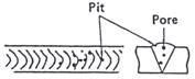
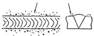
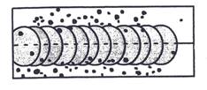
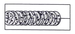
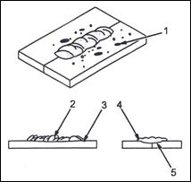
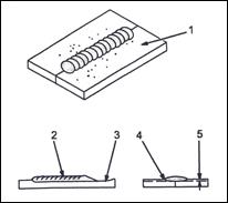
Metal inert gas arc welding, uses the short arc method which is a unique method of depositing molten drops of metal onto the base metal. Welding of thin sheet metal for automobiles can cause welding strain, blow holes and warped panels. To prevent these problems it is necessary to limit the amount of heat near the weld. The short arc method uses very thin welding rods, a low current and low voltage. By using this technique the amount of heat introduced into the panels is kept to a minimum and penetration of the base metal is quite shallow. The globular shifting condition of short arc welding is shown in the diagram below.
The end of the wire is melted by the heat of the arc and forms into a drop, which then comes in contact with the base metal and creates a short circuit. When this happens, a large current flows through the metal and the shorted portion is torn away by the pinch force which re-establishes the arc.
Unit Objective:
MIG Welding and Fabrication
By the end of this unit each apprentice will be able to:
Key Learning Points
1.0 Gas Cylinder Safety
1.1 Components used for storage and delivery of gases
BOC supplies equipment which is manufactured to the highest standards of quality and safety and will give first-class service for many years if operated correctly. The following notes will help to ensure your equipment is efficient and safe. Some suggestions for personal safety are also included. It is not intended to list every possible safeguard. These notes must be supplemented by caution and common sense on the part of the individual. Remember familiarity breeds over-confidence.
Safety precautions to be observed when using compressed gases with welding and cutting equipment are described in the companion booklet, "Safe under Pressure" available from your nearest BOC branch or Cylinder Centre. Data sheets and cylinder identification wall charts are also available.
1.2 Gas Cylinders
Leakage around the spindle of the cylinder valve will be revealed by hissing and in the case of fuel gases, by a smell. Tighten the gland nut on the cylinder valve slightly with a spanner (clockwise) and test with 1% solution of Teepol® HB7 in water. If still leaking, do not use the cylinder but label and return it. If the cylinder is owned by BOC, BOC will carry out an examination and replace it.
Never use a flame when testing for leaks.
Make certain that cylinders are well fastened in position so that they will not fall. Fit a cylinder key to the cylinder valve spindle and ensure that it is in the closed position (turned fully clockwise). The spindle key should remain in the valve the whole time the equipment is in use in case there is a requirement to shut off the gas supply in an emergency.
Never drop or abuse cylinders
When faced with an industrial gas cylinder full of gas and asked "what makes the cylinder potentially hazardous?" the average person is likely to mention:
Most people would not think to add:
ARC WELDING can be hazardous
Any exposure to a naked welding arc, even for a fraction of a second, is sufficient to damage the cornea of the eye (weld flash). Consequently a welding screen should always be used, preferably of the helmet and visor type. By using this type both hands are free for control over the welding equipment. The hand-held type of welding screen is of course fully adequate from a safety point of view but only leaves one hand free. This could result in a shakier movement of the gun and a loss of precision in following the joint.
Wear welding gloves and suitably fitting protective clothing. Especially when welding overhead so that the welding spatter does not run down the neck or sleeves of the overall worn.
Another hazard is the build-up of fumes given off by the welding process, which could be dangerous to health when welding in a confined space. When welding in a normal workshop there is no problem, but if welding in a tightly enclosed area, such as inside the boot of a car. Make sure that the area is well ventilated.
Precaution must be taken when welding vehicle panels in case there are flammable materials attached to the other side of the panel which could ignite and burst into flames. Therefore always have adequate fire-fighting appliances available.
2.0 M.I.G Welding/Fabrication Safety |
|
|
ELECTRIC SHOCK can kill. Always wear dry insulating gloves. Insulate yourself from work and ground. Do not touch live electrical parts. Keep all panels and covers securely in place.
|
|
FUMES AND GASES can be hazardous. Keep your head out of the fumes. Ventilate area, or use breathing device. Read Material Safety Data Sheets (MSDSs) and Manufacturer’s instructions for material used. |
|
WELDING can cause fire or explosion. Do not weld near flammable material. Watch for fire; keep extinguisher nearby. Do not locate unit over combustible surfaces. Do not weld on closed containers. Allow work and equipment to cool before handling. |
|
ARC RAYS can burn eyes and skin; NOISE can damage hearing. Wear welding helmet with correct shade of filter. Wear correct eye, ear and body protection. |
|
MOVING PARTS can cause injury. Keep away from pinch points such as drive rolls. Keep all doors, panels, cover and guards closed and securely in place. |
|
HOT PARTS can cause injury. Allow cooling period before touching welded metal. Wear protective gloves and clothing. |
|
MAGNETIC FIELDS FROM HIGH CURRENTS affect pacemaker operation. Pacemaker wearers keep away. Wearers should consult their doctor before going near arc welding, gouging or spot welding operations. |
|
ALWAYS EXAMINE WELDING CABLES for damage. Always report any damage. |
WELDING CURRENT can damage electronic parts in vehicles. Disconnect both battery cables before welding on a vehicle. Place work clamp as close to the weld as possible. |
|
2.1 Safety Precautions
SAFETY
The protective clothing and protective equipment used
for manual metal-arc welding are applicable. The amounts of ultra-violet and infra-red radiation, as well as the visible light radiation, are however more intense and full precautions must be exercised.
SAFETY PRECAUTION!
Check that there is good ventilation of the working area to prevent the build-up of harmful concentration of gases. Remember that carbon dioxide is heavier than air.
Always:
In confined spaces gas shields, if allowed to escape, may displace oxygen and cause suffocation. Degreasing agents such as trichloroethylene and carbon tetrachloride decompose around the arc to form poisonous compounds. Local fume extraction should be used when employing very high current densities or flux core electrode wire, and filter breathing pads to prevent inhaling oxide dust. Correct grades of screen glass should be used as ultra violet light is greater when welding aluminium with an argon shield compared with other processes. Remember to chalk HOT on materials after welding, especially aluminium. Use light gloves when T.A.G.S. welding to avoid burning through radiation and H.F. burns between the fingers. Adequate protective clothing should always be worn.
3.0 Development of Gas Shielded Arc Welding
Originally the process was evolved in America in 1940 for welding in the aircraft industry. It developed into the tungsten inert-gas shielded arc process which in turn led to shielded inert-gas metal arc welding. The latter became established in this country in 1952.
In the gas shielded arc process, heat is produced by the fusion of an electric arc maintained between the end of a metal electrode, either consumable or non-consumable, and the part to be welded, with a shield of protective gas surrounding the arc and the weld region.
3.1 The Metal Inert-Gas Shielded-Arc Process
This process employs a continuous feed electrode which is melted in the intense arc heat and deposited as weld metal, hence the term consumable electrode.
4.0 Operation Principles of M.I.G Welding Process
4.1 Functions of Gas and Operating Pressures
The sole function of the gas in gas-shielded welding is to protect the weld zone from the surrounding atmosphere and from the deleterious effects of oxygen, nitrogen and hydrogen upon the chemical composition and properties of the resulting weld. In this capacity the gas fulfils the major function of the fluxes used as electrode coverings or deposited as an enveloping layer during welding with established processes. The obvious advantages derived from the use of gas shielding are that the weld area is fully visible, that little, if any, slag is produced, and that the absence of abrasive flux increases the life of jigs and machine tools. In the MIG welding process gas shielding enables a high degree of mechanism of welding to be achieved. Few gases possess the required shielding properties, however, and those that do with certainly, the inert gases, notably argon are relatively expensive.
The shielding gases used in the MIG/MAG and TIG welding processes perform several important functions.
It is necessary to prevent contamination of the weld pool by atmospheric gases which cause deterioration of the weld bead quality, by surface oxidation, porosity or embrittlement. In the consumable electrode process MIG/MAG, it is also necessary to consider the potential loss alloying elements in the filler wire owing to preliminary oxidation in the arc atmosphere. In TIG welding oxidation of the non-consumable tungsten electrode must be prevented. For these reasons most welding shielding gases are based on the inert gases argon (Ar) and helium (He). Active gases such as carbon dioxide (CO2), oxygen (O2) and hydrogen (H2) may be
added to the shielding gas to control one or other of the functions stated, but the gas chosen must be compatible with the material being welded.
The successful exclusion of atmospheric contamination depends on the ability to provide a physical barrier to prevent entrainment in the arc area, and in the case of some reactive metals such as titanium it may be necessary to extend this cover to protect the solidified weld metal whilst it is cooling. The gas cover depends on the shielding efficiency of the torch and the physical properties of the gas. The higher the density of the gas the more resistant it will be to disturbance, and gases which are heavier than air may offer advantages in the down hand welding position. The shielding gas used in MIG/MAG processes displaces the air in the arc area. The arc is struck within this blanket of shielding gas, producing a weld pool free from atmospheric contamination. The type of gas used determines the heat input, arc stability and mode of transfer, as well as providing protection for the solidifying weld metal. With any gas used greatly influences the quality of weld deposit, weld penetration and weld appearance. The heat affected zone can also be influenced by the composition of the gas.
Table – Density of common welding shielding gases.
Gas |
Density (Kg/m³) |
Argon |
1.784 |
Helium |
0.178 |
Hydrogen |
0.083 |
Nitrogen |
1.161 |
Oxygen |
1.326 |
Carbon Dioxide |
1.977 |
4.2 Argon
Argon is one of the rare gases occurring in the atmosphere and is obtained from liquefied air in the course of the manufacture of oxygen. Argon is an inert gas. It does not burn, support combustion, or does not take part in any ordinary chemical reaction.
On account of its strongly inactive properties it can prevent oxidation or any other chemical reaction from taking place in the molten metal during the welding operation.
The argon is supplied in steel cylinders coloured blue, a full cylinder having approximately 200 bar pressure which is reduced by a regulator to approximately 15 litres per min when drawing for welding. Normally the cylinder should not be allowed to be empty below 2 bar. This prevents air from entering the cylinder and helps to preserve the purity of the contents. Gas pressures are shown as bar: 1 bar = 14.505 lbf/in²; 10lbf/in² = 0.689 bar. Gas consumptions are in litres per hour (litre/h): 1 ft³/h = 28.316 litre/h.
Argon has been more extensively used than helium because of a number of advantages:
The lower arc voltage characteristics of argon are used to advantage in the welding of thin metals, because the tendency towards burn-through is lessened. Pure argon can be used for welding aluminium and its alloys, copper, nickel, stainless steel and also for MIG brazing.
4.3 Argon Mixtures
The gas mixtures that are suitable for vehicle body repair work consist of 95 per cent argon and 5 per cent carbon dioxide. These mixtures give smoother results with a better cleaner and more attractive spatter-free weld finish. These gases can be used to weld low-carbon mild steel, high-strength steel (HSS) and very low-carbon rephosphorised steels.
4.4 Choice of shielding Gases
Shielding gases must be carefully chosen to suit their application. The selection will depend on:
Chemical and physical compatibility of welding shielding gases and materials:
Material |
Gas |
Compatibility |
Plain Carbon steel and low-alloy steel |
Argon, Helium, CO2 Oxygen |
No reaction Slight oxidation of alloying elements |
Austenitic Stainless steel |
Argon, Helium |
No reaction |
Aluminium and alloys |
Argon, Helium |
No reaction |
Copper |
Argon, Helium, N2 |
No reaction |
Nickel |
Argon, helium |
No reaction |
Titanium |
Argon, Helium |
No reaction |
4.5 Principles of Operation
Metal inert- gas or active gas shielded arc welding (consumable) is accomplished by means of a gas shielded arc maintained between the workpiece and a consumable electrode from which metal is transferred to the workpiece. The transfer of metal through the protected arc column provides greater efficiency of heat input than that obtained in the TIG welding process. The resulting high-intensity heat source permits very rapid welding. In this process a continuously fed electrode passes the pre-selected welding current upon the wire. The current causes the wire to melt at the set rate at which it is fed. The shielding gas issuing from the nozzle protects the weld metal deposit and the electrode from contamination by atmospheric conditions which might affect the welding process. The arc may be started by depressing the trigger of the welding gun and scratching the electrode wire end on the work.
The equipment is designed so that the wire automatically feeds into the weld area as soon as the arc is established. Most MIG/MAG welding sets that are manufactured for the automobile repair trade are semi-automatic, the operator only being concerned with the torch-to-work distance, torch manipulation and welding speed. Wire feed speeds, power settings and gas flow are all preset prior to commencement of welding.
4.6 MIG/MAG Spot/Plug Welding
An advantage of MIG/MAG welding is the ability of the process to be adopted for single-side spot welding applications, either semi or fully automatically. By extending the welding gun nozzle to contact the workpiece, one-sided spot welds may be performed using dip transfer conditions. Predetermined weld duration times may be suitable timer and, if desired, fully mechanised. Unlike resistance spot welding, no pressure is required on the workpiece with MIG/MAG spot welding, and neither is a backing block. Mismatch of the sheets is permissible with a maximum gap equivalent to half the sheet thickness, the extra metal being provided by the electrode wire. Up to 30 spots per minute may be welded, which compares reasonably well with the 100 spots per minute from resistance welding techniques. The deep penetration characteristics of this welding process enable spot welding of widely differing metal thicknesses to be performed successfully, together with multi-sheet thicknesses.
MIG/MAG plug welding differs from MIG/MAG spot welding in that the outer metal panel has a predrilled or punched hole which is filled up with the weld metal to form the “plug”. The hole sizes used are 5-6mm with currents of 50 – 60A for panel thicknesses of 0.75-1.2mm. Care should be taken when MIG/MAG plug welding to avoid an excess build-up of weld metal, to reduce the necessity of dressing the finished weld. The method is used to advantage in the fitting of new panel sections, where the original was resistance spot welded and access is now difficult to both sides.
Higher – strength steels are used for selected panel sections, but as they are vulnerable to heat they are not as easily welded as mild steel. MIG seam and butt welding produce hard weld joints; they will tear from the sheet metal on impact. However, MIG spot welds and particularly puddle (or plug) welded MIG spots can be made ductile. The weld time has to be short to reduce the heat-affected zone around the weld.
Modern car body designs are constructed with deformation zones both front and rear, and the shear impact properties of the original welding have been carefully calculated to ensure that the energy of an impact is fully absorbed and contained within the zone. Changing the manufacturer’s original welding specification could impair the safety of the vehicle. The crumplability (impact energy absorbing) design of the car bodies makes new demands on the welds. For its success the body design relies on the sheet metal to crumple or fold rather than tear in a collision. This protective design depends on the ductility of the metal, and the welds too have to be ductile. If they are soft they will break without forcing the assembly to crumple, but if they are hard the welds will unbutton and the assembly will fly apart instead of folding up slowly. Welds therefore must be ductile as well as large and strong.
4.7 Welding Current
A transformer supplies the electrical current that generates the arc. The transformer changes 200-240 V AC to 25-40 V DC. The control unit and the current regulator are made up of manual semiconductors.
A signal is sent from the gun switch to operate the feed control, the welding power supply and the shield gas flow. The arc will maintain a constant length if the wire speed and the starting and stopping of the operator corresponds to the current and voltage setting.
The welding current has a large effect on the penetration of the base metal (the depth of the melting that occurs in the base metal during welding) and the fusion speed of the wire.
The welding current also affects the stability of the arc and the amount of spatter, which are the slag and metal particles scattering during welding. Both the depth of penetration and the bead width increase as the wielding current increased.
When the arc voltage is high, the arc length increases, the penetration is shallow and the bead is wide and flat. When the arc voltage is low, the arc length decreases, penetration is deep and the bead is narrow and dome shaped.
Figure 2: Arc Voltage and Bead Shape
Since the length of the arc depends on the amount of voltage, voltage that is too high will result in an overly long arc and an increase in the amount of weld spatter. A sputtering sound and no arc means that the voltage is too low.
Figure 3: Arc Voltage
4.8 Arc Voltage
To obtain a good weld, the arc length is important. The length of the arc is determined by the arc voltage.
When the arc voltage is proper, a smooth buzzing sound is heard. If the arc voltage is too high, the arc length tends to become longer, and the amount of splatter also increases along with the puttering noise. On the other hand, if the arc voltage is too low, the wire dips into the molten pool and emits a banging sound without actually producing an arc.
4.9 Equipment used in MIG/MAG Welding
4.10 Safe Operation and use of M.I.G Welding Equipment
The basic equipment required comprises a power source, a wire feed unit and a torch, the power sources commonly used have constant-voltage characteristics, and controls are provided for voltage and inductance adjustment. This type of power source is used in conjunction with a wire feed unit which takes the wire from a spool and feeds it through a torch to the arc. A control on the wire feeder enables the speed of the wire to be set to a constant level which will in turn determine the arc current.
The welding torch should be reasonably light and easy to handle, with provision for gas shield shrouding, controls with, easy wire changes and good insulation. The torch is connected to a wire feed and control unit by means of:
The whole feed unit is bound together by a plastic sleeve, and is 1.5m to 3m long. The wire feed unit houses the drive unit for the wire feed, which can be varied in speed to suit current/voltage conditions. The wire reel is also carried in the unit and is loaded with some 15kg of welding wire.
5.0 Power Settings
DC power units are used as either rotary generators or rectifying units which are specially designed to give full versatility of arc control. The equipment is either single phase (130 -240 A) or three phase (250 -500 A). The principle components of most machines are welding transformer, rectifier, choke coil, wire feed unit, gas solenoid valve and electronic control box. The welding transformer is dimensioned so as to achieve optimal welding properties; the transformer is manufactured from materials able to withstand a working temperature of up to 180ºC. By way of a further safeguard against overloading, there is a built-in thermal fuse which cuts out the machine at 120ºC. The thermal fuse is automatically reconnected once the transformer has cooled down.
The rectifier is constructed from a fan, thyristors, diodes and a capacitor battery. During welding, or when the machine is hotter than 70ºC, the fan cools the rectifier and the transformer. The rectifier is electronically protected against over-loading in the event of any short-circuit between welding positive and negative, with the machine cutting out approximately 1 second after the onset of short-circuiting.
The transformer converts the high mains voltage into a low alternating voltage, which is rectified and equalized into DC voltage in the rectifier module. A choke coil reduces the peaks in the welding current and thus eliminates the cause of welding spatter. When the switch on the torch is depressed, the thyristors come on. The rectifier emits a DC voltage, which is determined by remote regulation from the torch.
When the trigger is released the motor decelerates, and after a short time lag the gas flow and the welding voltage are interrupted. This time delay is called burn-back and causes the welding wire to burn a little way back from the molten pool, thus preventing it from sticking to the workpiece.
Depending on the type of equipment selected, the following functions are available: seam, spot, stitch and latching (four -cycle).
5.1 Wire Speed Settings and Timer
Selection switch: This selects between the functions seam, spot, stitch and latch.
Power light: This lights up when the machine has been turned on.
Overheating warning light: If this light comes on, the welding equipment is automatically switched off owing to overheating of the transformer. When the temperature is back to normal, the welding can be continued.
Welding timer switch: With this switch the welding time is chosen, when the selection switch is in the stitch or spot position.
Adjustable pause time button: With this button the pause time is chosen, when the selection switch is in the stitch position.
Burn-back button: Pre-adjustment of the burn-back delay button indicates the time for stopping the wire feed until the arc is switched off. This varies between 0.05 and 0.5 s.
Adjustment of wire speed switch: This gives the adjustment of the wire feed from 0.5 to 14m/min.
Welding voltage switch: This sets the welding voltage of the transformer. When set at gas test, the gas flows by pressing the switch on the torch handle.
The characteristics built into the welding power supply are such as to provide automatic self-adjustment of arc conditions as the weld proceeds. Depending on the relevant current and voltage used, metal transfer between electrode and work takes place in the following distinct forms each of which has certain operational advantages.
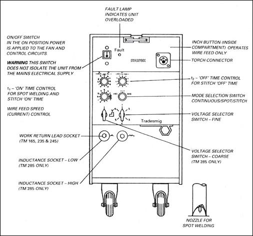 Figure 4: Power Unit
5.2 Seam
Welding starts when the switch on the welding trigger is actuated and stops when the switch is released. For use in short-duration welding and tacking.
5.3 Spot
Welding starts when the switch is actuated and is subsequently controlled by the welding timer for a time between 0.2 and 2.5 s. It makes no difference when the switch is released. This function ensures uniform spot welds, providing the correct setting has been found.
5.4 Stitch
The wire feed motor starts and stops at intervals which are set on the welding timer and pause timer. When welding is interspersed with pauses in this way, the average amount of added heat is reduced, which prevents any melting through on difficult welding jobs.
5.5 Latching
Welding starts when the switch is actuated; the switch can then be released and welding continues. By reactivating the switch, welding stops when the switch is released. For use on long seams.
6.0 Principle of Operation of the MIG Welding Process
6.1 Dip Transfer (short arc)
This condition requires comparatively low current and voltage values. Metal is transferred by a rapidly repeated series of short circuits when the electrode is fed forward into the weld pool.
Metal dip transfer is the most suitable mode of metal transfer for welding on car repairs, as it offers good bead control and low heat input, thus cutting down distortion when welding in panel sections. This type of transfer will also permit the welding of thinner gauges of sheet steel, and is practical for welding in all positions.
For this type of transfer a power source giving an output of about 200 amperes with open circuit voltage tappings from 15-30 volts is appropriate. Inductance control must be incorporated. When the arc length is short (i.e. arc voltage is low) the end of the electrode wire touches the weld pool and the current rises.
If the rate at which the current rises is controlled, the end of the electrode is melted off and flows into the weld pool. This is known as Dip Transfer and is only applicable to materials having a relatively high electrical resistance, e.g. steel.
Figure 5: MIG Welding Control Panel
Figure 6: Schematic Diagram, Dip-Transfer
For this type of transfer the high current pulses may be obtained from a single phase rectifier connected to a rectifier power source as used for dip transfer.
With pulse transfer the welding current alternates between high and low levels. A high current density detaches droplets of metal and a low current density maintains the arc. By this means a form of controlled spray transfer is obtained at low current values.
Typical operating ranges are shown for Spray, Dip and Pulse Transfer for 3/64˝ (1.25 mm) dia. Mild steel wire.
6.3 Spray Transfer
For this type of transfer a power source giving an output of about 400 amperes with an open-circuit voltage within the range 25-50 volts may be used.
With high current density, and particularly when using an aluminium or aluminium alloy electrode wire, the metal transfer is in the form of tiny drops when using argon shielding.
Spray transfer can be used for aluminium in any position, with appropriate reduction in welding current. This mode of transfer can only be used satisfactorily on other metals when welding in the flat position.
Even, when using the smallest diameter wire, the minimum current is in the order of 160 amperes. For welding in position or for the welding of thin materials dip or pulsed transfer is used.
6.4 Metal Transfer Forms
Figure 8: Metal Transfer Forms
6.5 Suitable Filler Wire Diameter
Basic maintenance of the welding torch and wire feed mechanism.
This device feeds the wire used as a welding rod to the torch. The wire is fed to the work area at a predetermined rate which corresponds to the welding current, voltage and speed of the operator.
The consumable electrode for welding ferrous and non-ferrous materials is supplied as a continuous length of wire on a spool or reel, and the wire varies from 0.6 to 0.8mm diameter. The feeding of the wire is achieved by the unit feed mechanism housing the necessary drive motor, gear box and feed rolls which draws wire form the adjacent reel, or by an integrally built motor drive connected to the torch which pulls the wire in the desired direction. The feed wire unit also houses the controls which govern the feeding of the wire at the required constant speed, plus the automatic control of current and gas flow. The wire from the feed rolls is fed along a carefully designed conduit system which also carries the welding current and shielding gas. The outer end of this conduit system is connected directly to the welding torch.
6.6 Welding Equipment Construction
Welding equipment consists of a torch, wire feeder, shield gas supply, control device, and power source. Various types of welding equipment are available, depending on the combination of devices, most models are similar.
Air cooled torches are available for the various welding applications ranging from 180 A to 400 A. The design of the torch is in the form of a pistol or is curved similar to the shape of an oxy-acetylene torch and has wire fed through the barrel or handle. In some versions where the most efficient cooling is needed, water is directed through passages in the torch to cool the wire contact means as well as the normally cooled metal shielding gas nozzle. The curved torch carries the current contact tip at the front end through which the feed wire. Shielding gas and cooling water are also brought. This type of torch is designed for small diameter feed wires, is extremely flexible and maneuverable and is particularly suitable for welding in confined areas. The service lines consisting of the power cable, water hose and gas hose on most equipment enter at the handle or rear barrel section of the torch. The torch also is equipped with a switch for energising the power supply and controls associated with the process. Some welding torches also have a current control knob located in the torch so that welding current can be altered during welding. This ensures that the welding voltage is altered at the same as any current alteration, so allowing the welder to respond immediately to variations in weld gaps and misaligned joints. Welding characteristics are excellent. Fingertip control increases both productivity and weld quality.
Figure 11: Air-Cooled Welding Torch.
6.8 Torch
In addition to spraying the shield gas onto the area to be welded, VIA (nozzle/shroud) current is transmitted from the torch to the wire (contact tip) to generate a short arc. It is also provided with a switch on its grip which allows the operator to begin and end welding.
Weld splatter must be removed promptly if it adheres to the end of the welding nozzle, as it will interrupt the shield gas flow resulting in a poor weld. It will also prevent the welding wire from feeding through correctly and causes it to back up inside the welder, causing problems with the feed mechanism. Use a suitable tool (such as a pair of wire nippers) to remove any spatter build-up from the wire tip and check for correct operation. The use of anti-spatter compound will reduce the amount of build-up on the nozzle and wire.
Figure 13: Removing Spatter.
There is tendency for the welding nozzle tip to become worn with use and this will affect the quality of the welding arc. The tip should therefore be renewed and kept properly tightened. This will ensure a good, stable arc and consistent current flow.
Figure 14 : Nozzle Tip
6.10 Operating the Equipment
Controls
All equipment will have the following controls:
Equipment designed specifically for Dip Transfer welding will have an additional control:
Equipment designed for Pulse Transfer will have additional controls:
sources.
.
Do-not touch electrode wire when the current is switched on.
6.11 Operation Method
The proper handling of welding equipment is an essential ingredient in successful welding. Here are some pointers on the proper handling of welders.
Arc Generation
Position the tip of the gun near the base metal. When the gun switch is activated, the wire is fed at the same time as the shield gas. Bring the end of the wire in contact with the base metal and create an arc.
Note: If the distance between the tip and the base metal is shortened a little, it will be easy to generate.
Figure 16 : Arc Generation
If the end of the wire forms a large ball, it will be difficult to generate an arc, so quickly cut off the end of the wire with a pair of wire cutters.
Hold the tip of the gun away from your face when cutting off the end of the wire.
7.0 Functions of Shielding Gas
7.1 Shield Gas Supply Equipment
This equipment guides the shield gas from the gas cylinder to the gun. The regulator reduces the high pressure gas that is stored in the cylinder to a constant pressure and flow rate. An electromagnetic valve starts and stops the flow of shield gas.
7.2 Shield Gas Supply
The primary purpose of the shielding gas used in MIG/MAG welding is the protection of the molten weld metal from contamination and damage by the oxygen, nitrogen, water vapour and other gases in the surrounding atmosphere. However, in use there are a number of other factors which influence the desirability of a gas for arc shielding. Some of these are the influence of the shielding gas on the arcing and metal transfer characteristics during welding, on the weld penetration, width of fusion and surface shape patterns, and on the speed of welding. All of these influence the finished welds and overall results. Normal shielding gases in use are argon, carbon dioxide and other mixtures of argon and carbon dioxide, although other mixtures such as argon and oxygen can be used.
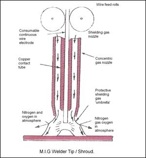
Figure 18: M.I.G. Welder Tip/ Shroud
7.3 Shield Gas Flow Rate
Take care not to use too much shield gas flow. If the flow is excessive, it may actually cause a disturbance and result in a poor shield effect. The standard amount of shield gas flow rate is between 10 to 12 litres/min. and must be regulated according to the distance between the nozzle and base metal, welding current, welding speed and the welding environment (wind velocity). The latest steels, if M.I.G welded are best welded at lower flow rates than the standard. These can be as low as 6-8 litres per min. this is done to minimise hardening to the cooling effect of the gas flow.
7.4 Tip-Base Metal Distance
The distance between the electrode tip and the base metal is another essential factor for obtaining good weld. The standard distance is between 6 to 13mm. if the distance is too large, the melting rate of the wire becomes too fast. This is because the length becomes preheated. As a result the current will decrease producing a shallower penetration. Also if the distance is too large, the shielded effect of the gas will be reduced. If it is too small, it makes it more difficult for the operator to see the portion being welded.
7.5
Components used for Storage and Delivery of Gases
Cylinder Recognition |
|
Argon |
Blue |
Argon-Oxygen |
Blue with black band |
Argon-Carbon Dioxide |
Blue with green band |
Alternatively cylinders containing mixed gases may be painted with aluminium paint and the name of the mixture stenciled in black |
|
Inert Gas
Argon of welding grade purity is used as the shielding gas when welding non-ferrous metals.
Argon-Oxygen Mixtures
The addition of small quantities of oxygen to argon makes it more suitable for use when welding steels.
About 1 % of oxygen is added when used for welding stainless steels and up to 5% when used for welding mild steel by spray-transfer technique.
For pulse transfer technique, argon mixed with up to 2% of oxygen and up to 5% of carbon dioxide with small percentages of other gases, is used for welding steels.
Argon-Carbon Dioxide Mixtures
Dip and spray transfer welding techniques are possible with a mixed shielding gas of 80% argon and 20% carbon dioxide. The spray transfer can be further improved by the inclusion of up to 2% of oxygen.
Gas Mixtures
These mixtures are supplied in steel cylinders. Alternatively separate gases may be mixed in the proportions required by the use of a gas mixer.
Carbon Dioxide
Carbon dioxide is used as a shielding gas for mild steel welding, and is cheaper than argon-rich gases. It is more suitable for dip transfer at low currents but can be used at high currents for a form of spray or 'free flight' transfer. There are two types of internal fittings to the cylinders; one which allows gas, which might contain moisture, to be ejected on opening the valve, and the other called the syphon-type which only allows liquid carbon dioxide to be ejected
Figure 20: Carbon Dioxide Cylinder
7.6 Shielding Gas
It must be appreciated, that with any gas shielded-arc process, the type of shielding gas used greatly influences the quality of the weld deposit. Weld penetration, appearance and the heat affected zone can also be influenced by the composition of the gas.
7.7 Gases
Since CO2 and oxygen are not inert gases, the title metallic inert gas is not true when either of these gases is mixed with argon or CO2 is used on its own. The title metallic active gas (MAG) is sometimes used in these cases.
Argon + 1% or 2% oxygen. The addition of oxygen as a small percentage to argon gives higher arc temperatures and the oxygen acts as a wetting agent to the molten pool, making it more fluid and stabilising the arc.
Gas flow rate can greatly affect the quality of the weld. Too low a flow rate gives inadequate gas shielding and leads to the inclusion of oxides and nitrides, while too high a rate can introduce a turbulent flow of the CO2 which occurs at a lower rate than with argon. This affects the efficiency of the shield and leads to a porosity in the weld. The aim should be to achieve an even non-turbulent flow and for this reason spatter should not be allowed to accumulate on the nozzle, which should be directed as nearly as possible at 90° to the weld, again to avoid turbulence.
The torch angle is, in practice, about 70-80° to the line of travel consistent with good visibility and the nozzle is held about 10-18 mm from the work. If the torch is held too close, excess spatter build-up necessitates frequent cleaning, and in deep U or V preparation the angle can be increased to obtain better access. Weaving is generally kept as low as convenient to preserve the efficiency of the gas shield and reduce the tendency to porosity. Wide weld beads can be made up of narrower 'stringer' runs, and tilted fillets compared with HV fillets give equal leg length more easily, with better profile.
7.8 Gas Flow Regulation
The recommended shielding gases for a specific grade and thickness of HS steel are based upon a starting setting of 15 ltrs/min. This flow rate may be increased or decreased depending upon the welding application. Final adjustments must often be made on a trial and error basis.
8.0 MIG Welding Techniques
In the operation of a MIG/MAG welding machine there are two parameter settings which must match each other: the wire speed and the welding voltage. It is important therefore that the wire speed and the welding voltage are adjusted to conform with each other. The wire speed gives the welding current, which must match the component panel section being melted. An increase in wire feed rate increases the welding current, at the same time reducing the length of arc, resulting in a shorter arc. When the wire speed is reduced, the current intensity is diminished, at the same time increasing the length of the arc. Raising the open-circuit voltage increases the arc voltage, though the current intensity remains almost constant. A reduced open-circuit voltage will produce a shorter arc length. A change in welding wire diameter will produce a change in current and voltage, since thinner wires require higher voltage and higher wire speeds in order to produce the same current. If the limit values are exceeded a satisfactory weld cannot be obtained.
When the wire speed setting is too low, this will cause a long, drawn-out arc and splattering and very unsatisfactory weld conditions. When the wire speed becomes too great in relation to the voltage, knocking or stubbing will be felt in the welding torch, because the wire travels to the bottom of the molten pool. Welding under these conditions will normally produce adhesion defects owing to the lack of fusion. If the voltage becomes too great in relation to the wire speed, large drops will form on the end of the wire. These will be reluctant to leave the end of the wire and will often settle as splatter beside the weld. When the ratio between the voltage and the wire is correct, a highly characteristic hiss or hum will be heard from the arc.
The mutual position of the welding torch and workpiece in relation to each other is of importance to the appearance and quality of welding. In practice many different combinations of inclination, torch handling and welding position will be experienced by the body repairer.
8.1 Control Device
An electronic circuit made up of numerous semiconductors, the control device is enclosed within the power source area. Once the signal from the torch switch is received, the control device will tell the wire feeder to feed, the welding current to open or close, ad the shield gas to flow or stop. Of these functions the most important is the wire feeding speed of the wire according to the current and voltage being used.
This control is designed to maintain the arc length at a constant length.
Power source – a device to supply the electrical power needed for generating arcs.
8.2 Welding Conditions
Some of the factors which will affect the weld are: the welding current, arc voltage, shield gas flow rate, tip-base metal distance, torch angle, welding direction and welding speed. Of these factors, the welding current, arc voltage and the amount of shield gas flow rate must be adjusted according to the each operational manual.
8.3 Torch Angle and Welding Direction
There are two types of welding direction, forehand welding will produce a flatter bead with a shallower penetration, while a backhand welding will produce a bead with a deep penetration and excess. The angle of the torch should be between 60 degrees in either type of welding.
Welding positions can be as follows: flat, horizontal, vertical, overhead and owing to the complexities of panel shapes, a combination of these. In collision repair, the welding position is usually dictated by the location of the weld in the structure or panel assembly of the vehicle. Both heat and wire speed parameters can be affected by the welding positions.
Flat welding is generally easier and faster and allows for better penetration. When welding a panel section that is off the vehicle, try to place it so that it can be welded in a flat position.
When welding a horizontal joint, angle the welding torch upwards to hold the weld puddle in place against the pull of gravity. When welding a vertical joint, the best procedure is usually to start the weld at the top of the joint and pull downwards with a steady drag.
Overhead welding is the most difficult. In this position the danger of having too large a weld puddle is that some of the molten weld metal can fall down, either into the nozzle where it can create problems, or on the operator. Therefore always carry out overhead welding on a low voltage setting, which will cut down spatter while
keeping the arc as short as possible and the weld puddle as small as possible. Press the nozzle of the torch against the work to ensure that the wire is now moved away from the puddle. It is better to pull the torch along the joint with a steady drag.
8.4 Welding Wire Diameters
The welding wires used for MIG/MAG welding are quite small in diameter compared with those used for other types of welding. Welding wire is 0.6 – 1.0 mm in diameter, and is supplied in reels of 5 – 15kg. Owing to the small size of the wire and comparatively high currents used for welding, and wire melts off very rapidly, therefore the wires used must always be as long as possible, with suitable temper for being fed smoothly and continuously by motor driven mechanical means through the welding apparatus. For this reason the wire is normally provided on convenient size coils or spools.
In composition the wires are usually quite similar to those used by most other bare wire processes. As a rule the composition matches that of the base material as is practicable, while also ensuring good weld properties and welding characteristics. Steel wires are often given a light coating of copper to prevent them from rusting and to improve the electrical contact and current pick-up when passing through the welding apparatus. Welding wires are available for joining most ferrous and non-ferrous metals.
8.5 Solid Wire
The composition of solid filler wire is usually chosen to match the parent metal being welded. Solid wire is the most common and widely used filler material for MIG/MAG welding car body replacement panels.
8.6 Cord Wires
Metal and flux corded wires are available. These materials are, however, more suitable for welding thicknesses in excess of 6mm. Metal corded wires can be obtained with additions of alloying elements to meet special requirements (HS low-alloy steels).
8.7 Conditions that Affect Weld Bead Shape
Note: Weld bead shape depends on gun angle, direction of travel, electrode extension (stick-out), travel speed, thickness of base metal, wire feed speed (weld current) and voltage.
Figure 23: Conditions that Affect Weld Bead Shape
8.8 Holding and Positioning Welding Gun
Note: welding wire is energized when the gun trigger is pressed. Before lowering helmet and pressing trigger, be sure the wire is no more than ½ in. (13mm) past end nozzle, and tip of wire is positioned correctly on seam.
9.1 Gun Movement during Welding
Note: Normally, a single stringer bead is satisfactory for most narrow groove weld joints; however, for weld groove weld joints or bridging across gaps, a weave bead or multiple stringer beads works better.
9.2 Permanent Welding
Support the gun securely so it does not wobble. Use the forward method, moving the torch continuously at a constant speed, looking frequently at the welding bead. The gun should be inclined between 10º -15ºto obtain the best bead shape, welding line and shield effect. Maintain proper tip-base metal distance and correct gun angle.
If the weld is not progressing well the problem may be that the wire
length is too long. If this is the case, penetration of the metal will not be adequate. For proper penetration and better weld, bring the gun closer to the base metal.
9.3 Continuous Weld
A continuous weld is an uninterrupted seam or weld bead which is carried out as one steady progressive movement. While supporting the torch securely, use a forward movement to move the torch continuously at a constant speed, checking the weld bead frequently as you progress. When the torch handling is smooth and even, the weld bead will be of consistent height and width with a uniform closely spaced ripple. Penetrate both metal panel pieces through the joint position while triggering a timed impulse of wire feed.
9.4 Welding Techniques
Even if the proper bead is formed during butt welding, panel warpage may result if the weld is started at or near the edge of the metal. Therefore, to prevent panel warpage, disperse the heat into the base metal by starting the weld in the centre of the panel and frequently change the location of the weld area, the thinner the panel thickness, the shorter the bead length.
Figure 29: Preventing Panel Warpage
9.5 Butt Welding of Thin Panels
Up to this point our explanation has covered the basics of butt welding of thick panels such as side members and frame rails. However, this method cannot be used effectively on thin outer panels. Therefore, the body repairman also needs to know how to butt weld thin panels.
9.6 Gun Switch Operation Method
 If continuous welding is done on a panel, there is a strong possibility of a burn-through. Therefore, thin steel panels that are 0.8mm (0.030 in.) or less should be welded intermittently or in cycles.
9.7 Butt Welding Method
Two panels are butted together end to end, then welded together in one continuous seam. Butt welding is used in areas where panels are replaced in sections. For example, the rear section of the quarter panel is butt welded to the front section of the same panel to form one continuous panel.
9.8 Temporary Welding
Tack welds are used along the butted seam to hold the panels together and prevent warpage. The length of the tack weld is determined by the thickness of the panel. Ordinarily, a length of 15 – 30 times the thickness of the panel is appropriate see figure 31.
Important: temporary welds are very important in maintaining proper alignment and must be done accurately.
9.9 Tack Weld
A tack is a relatively small temporary MIG/MAG weld that is used instead of a clamp or a self-tapping screw, to tack and hold the panel in place while proceeding to make a permanent weld, like the clamp or self-tapping screw, the tack weld is always and only is a temporary device. The length of the tack weld is determined by the thickness of the metal panel to be welded and is approximately a length of 15 to 30 times the thickness of the metal panel. Tack welds must be done accurately, as they are very important in maintaining proper panel alignment.
9.10 Plug Welding Method
A plug weld is used to join two metal panels together. The outer metal panel is first pre-drilled or punched. Next the arc is directed through the hole to penetrate the inner metal panel. The hole is then filled with molten metal to form the plug.
The most common type of shield gas arc welding is the plug weld type, which is explained briefly below.
Figure 33. Shows an example of the plug welding method. Holes are made in one or more of the panels to be joined, then they are fastened tightly together. The holes are filled until a small mound of welding material appears on the surface of the sheet metal.
9.11 Making Holes
To assure proper welding strength, make holes in the top panel with a drill, hole saw or similar device. Change the hole diameter according to the panel thickness.
Panel Thickness at the Welded Portion mm (in.) |
Plug Welding Hole Diameter mm (in.) |
Less than 1.0 (0.039) |
Ø 5 (0.20) or more |
1.0 (0.039) up to 1.6 (0.063) |
Ø 6.5 (0.26) or more |
1.6 (0.063) up to 2.3 (0.091) |
Ø 8 (0.31) or more |
2.3 (0.091) or more |
Ø 10 (0.39) or more |
9.12 Lap Spot Weld
In the MIG/MAG lap spot weld technique, the arc is directed to penetrate equally between the edge of the upper metal panel and the top surface of the lower metal panel of the lap joint and the puddle is allowed to flow on to the edges of the top piece. This is achieved by using the correct angle of the welding torch to the joint.
9.13 Stitch Weld
A MIG/MAG stitch weld is a series of intermittent seam welds carried out at intervals along a lapped metal panel joint, where continuous weld is not necessary or would cause distortion due to heat input.
|
Thrusting Weld |
Drawing Weld |
Width of seam |
Wider |
Narrower |
Upper bead |
Smaller |
Larger |
Penetration |
Decrease |
Increase |
Tendency to lack fusion |
Greater |
Lesser |
Clamping
Clamp the panels together with a vise grip wrench or similar device. If a deformation remains in the panel, shape it with a body hammer to make it fit properly. If the welding is done on poor fitting panels, the top panel will melt, the hole will spread and the weld will be inferior.
9.14 Applications of MIG/MAG welding in vehicle body repair construction.
The continuous search for increased efficiency in production techniques in the automotive industry has led to all major manufacturers adopting the use of MIG/MAG. This welding process is ideally suited to flow line production processes owing to its inherent automatic characteristics. MIG/MAG welding has numerous advantages over the majority of processes likely to be encountered in automotive production. Most obvious is its capability to be used semi or fully automatically, thus giving it virtually unrivalled versatility. In automobile construction it has almost totally replaced oxy – acetylene and manual metal arc welding by virtue of its high metal deposition rates, electrode efficiency and high duty cycles. Further advantages of the process are good penetration, even without edge preparation, the ability to handle all metal thickness and high weld strength (618 MN/m² being easily achieved).
MIG/MAG dip transfer welding is a low heat input process owing to the relatively low amperages required, and it is ideal for welding fine sheet thickness because of the absence of distortion with minimal jigging. With the absence of flux further advantages accrue, the most obvious ones being the elimination of deslagging and chipping back when second weld starts are required. The absence of flux also means, the welder has a clear view of arc operation and weld bead appearance and is not subjected to excessive fumes. Spatter is minimal and weld bead appearance enhanced owing to the improved wetting of the parent material by molten metal on account of the various additives present in the wire composition.
The MIG/MAG welding process can in many ways replace existing welding techniques, usually manual metal arc and oxy-acetylene, to give superior welding conditions and economies. Semi-automatic and more particularly fully automatic MIG/MAG welding processes with a wide range of technical advances have opened up new areas of production technique. Numerous companies in the United Kingdom have already adopted MIG/MAG welding to their
own particular requirements. On a modern mass produced passenger car the body shell is a relatively low-stressed unit, high stresses are imposed by road conditions being carried by sub-frame assemblies. However where continuous welds are required or specific components carrying high stresses are to be fitted MIG/MAG welding is employed using semi-automatic equipment. Thus components such as safety harness attachments, door hinges, jacket points, spring shackles, steering column brackets and seat frame guides are attached using the dip transfer technique, which enables welds of this type to be made on thin shell panels with no distortion of the panel and deep penetration into the thicker work-piece. Where MIG/MAG welding has been introduced into automotive production lines, its value as a production process is well established.
9.15 Applications of MIG/MAG welding in body repair work.
The semi automatic MIG/MAG welding process which is used in the construction of vehicle bodies is also used for the repair of these bodies. Equipment is now especially used for thin-gauge in the repair of vehicle bodywork.
Welding in the repair of car bodies was mainly carried out using oxy-acetylene and resistance spot welding techniques. Both of these techniques have certain disadvantages. In the oxy-acetylene method the weld metal and surrounding panels are likely to distort to heat input. In spot welding if the repair is visible the joints, which in most cases are lapped, must be solder filled to achieve an acceptable finish.
The advantage of MIG/MAG welding equipment in repair are first that it is a dual machine being capable of welding in any position, and it can weld material from 0.5mm to 4.4mm in thickness. Second, it can be used for spot welding from one side of the panel only, which is an advantage when welding inaccessible panel assemblies. The equipment itself is very portable, consisting of a transformer, rectifier, built in feed wire system, lightweight welding
torch with interchangeable nozzle heads for conventional welding and spot welding, earthing cable and clamp and gas supply in steel cylinders, all of which are incorporated on a maneuverable trolley which lends itself to bodywork application in the workshop. Most equipment used in the motor body repair usually has the following controls and functions: a weld timer which can be set from 0.2 to (usually) 2.5 seconds; some form of wire speed control which ranges from 2 to 12m/min; and a voltage control usually ranging from 0 to 10, the 0 setting giving the lowest welding current. On some machines the settings for wire speed and welding voltage are coupled together into one control, which can either be on the machine or positioned on the welding torch for instant adjustment. The following function controls are the most widely used: seam for continuous welding; spot, which makes use of a time setting to ensure uniform spot welds: and stitch, which is used through the weld timer and pause timer and provides intermittent welding so that welding is interspersed with pauses, therefore reducing heat input and preventing melt through on thin materials and gapped joints.
9.16 Preparing the equipment for welding
For best results for seam, spot or stitch welding, the surface of the panel should be cleaned to bare metal condition as paint or grease cause bad welds. In body work applications the heat input is limited on each side of the weld owing to the shielding gas; this has the effect of reducing possible distortion to a minimum so that adjacent parts do not get so hot as to damage trim, screen rubbers and windscreen glass. It can also be used to great advantage in repairing by sectioning or patching, as two sections can be butt welded and the weld completely dressed off on one side with a sanding
machine. Finish off using normal panel beating hand tools to create a perfect finish. As this system of welding gives a perfectly controlled penetrating weld of great strength, it will be found ideal for replacing new panel sections such as sub-frame and under-frame members, where the welding is highly critical because of the stress factor present in load-bearing assemblies. The speed at which this welding can be carried out in the repair of the modern mono constructed body shell is proving itself to be an economical asset.
9.17 MIG/MAG welding of low-carbon steel and HSLA steels
Until the mid 1970’s most if not all vehicles bodies were constructed from plain low-carbon steel, but since then there has been an increase in the world-wide demand for corrosion resistance in body structures. This has led to the introduction of single sided and double sided coated galvanised steel, high strength steel and aluminium. The Japanese, in particular, and the European industries have moved to the use of HSLA steels in further attempts to reduce body eight. Body skin panels have been reduced from around 0.9mm to 0.7mm, with structural components reduced from 3mm to between 1.2mm and 2.0mm.
The use of these different materials can lead to problems for the welder. Welding galvanised steels (zinc coated) can reduce rust resistant properties around the weld areas if they are not correctly treated.
Cosmetic body panels are the thinnest panels on the vehicle, and are generally repaired by the use of butt, fillet, lapped edge or corner joints. It is therefore necessary to use as low a current as possible when using the MIG/MAG process on these thin panels. The choice of shielding gas for the process is important as it affects not only the quality of the weld, but also the depth of penetration of the weld into the material and the amount of weld spatter that is formed around the finished weld. It also controls the temperature, which affects the suitability of the process for the thickness of materials to be welded.
The choice of shielding gases commonly used can be seen in the Table below.
Application |
Metal Thick-ness (mm) |
Shielding Gas |
Wire Dia-Ø (mm) |
Current (A) |
Voltage (V) |
Wire Speed m/mm |
Welding Speed mm/min |
Gas Flow 1/min |
Horizontal Vertical Fillet |
1.0 1.6 |
Argoshield 5 Argoshield 5 Argoshield 5 Argoshield TC Argoshield TC Argoshield TC Argoshield TC |
0.8 0.8 1.0 1.0 1.2 1.2 1.2 |
66 130 160 180 180 260 290 |
14 18 17 20 17 27 27 |
3.4 9.7 5.9 6.4 3.8 7.0 7.4 |
900 600 563 391 430 480 430 |
12 14 14 15 15 16 16 |
|
||||||||
Butt Weld, flat position |
1.0 1.6 |
Argoshield 5 Argoshield 5 Argoshield 5 Argoshield TC Argoshield TC Argoshield TC |
0.8 0.8 1.0 1.0 1.2 1.2 |
66 84 125 140 300 300 320 |
14 18 16 19 28 28 28 |
3.0 4.0 4.0 4.0 7.6 7.6 7.6 |
750 800 640 350 650 680 580 |
12 14 14 15 16 16 16 |
|
||||||||
Butt Weld, Overhead |
1.0 1.6 3.0 |
Argoshield 5 Argoshield 5 Argoshield TC |
0.8 1.0 1.2 |
50 150 180 |
15 17 19 |
4.0 5.9 4.3 |
360 600 520 |
12 14 15 |
|
||||||||
Butt Weld, Vertical up |
1.0 1.6 3.0 |
Argoshield 5 Argoshield 5 Argoshield TC |
0.8 1.0 1.2 |
45 130 135 |
15 17 17 |
3.5 4.7 3.1 |
350 410 275 |
12 14 14 |
Under the right conditions, any of the gases shown in the table can be used for the range of thickness encountered in the body shop however, the ideal for welding thin body panels is the colder mixture of argon with 2 per cent oxygen and five per cent carbon dioxide. When welding structural components and chassis members the material tends to be thicker, up to 3mm or even more, it is necessary to use a hot arc in order to penetrate the material. For this reason a mixture of argon with 2 per cent oxygen and 12 per cent carbon dioxide is used to give better heat flow, greater tolerance to variation in setting, and low spatter generation. It is also a common practice to increase the wire diameter from 0.6mm to 0.8mm when welding these thicker panel assemblies.
10.0 Welding Stress and Distortion in the MIG/MAG Process.
The MIG/MAG welding process and its effectiveness may be measured by its ability to produce joints of acceptable quality. Unacceptable joint quality may arise from a failure in the specific design or from the incident of a weld defect. These problems however are preventable if their causes are understood and the correct procedures are followed.
The most common welding problems are:
Residual stress and distortion
The solidification and contraction of the weld bead will induce strain and consequently stresses in the joint. In the case of the contraction of the solid metal the stress will be equal to the change in temperature as the metal cools from its melting point to its ambient temperature. Under normal circumstances movement of the weld bead is restricted by the adjacent body panels in the vehicle structure, and the stress that could be generated is given by the Young’s modulus of the material. This stress level often exceeds the elastic limit of the material and plastic deformation takes place. The stresses locked in the material, which may reach levels up to the elastic limit of the material, are called residual stresses, and the deformation of the material is known as distortion.
Residual Stresses
In a butt weld the weld bead will tend to contract longitudinally and transversely, and this will induce tensile stresses in the weld and also balancing compressive stresses locked in the sheet material. In the
joining processes which rely on heating or fusion, it is difficult to prevent the formation of residual stresses. If the heat affected zone is ductile and defect free (as in thin-sheet panel steel) the presence of some residual stresses may be acceptable. The most common technique used to relieve residual stress in thicker materials is post-weld heat treatment. This consists of uniform heating of the joint to a temperature at which the yield stress of the material is lowered and the residual stresses are relieved by plastic deformation.
10.1 Distortion
Distortion may take the form of a change in dimensions of the joint, transverse or longitudinal shrinkage, angular movement, or out-of-plane buckling. Distortion may result in unacceptable appearance (buckled body panels), prevention of sub-assembly fabrication or the inability of the structure to perform its intended function (alignment of body panels after welding) the following steps may be taken to minimize distortion:
1. Use the minimum amount of weld metal. Over welding and excessive reinforcement should be avoided in fillet welds and flat butt welds. Intermittent or stitch welding may be used.
2. Use square edge on narrow gap procedures to reduce angular distortion when welding.
3. Use high travel speed and low heat input to limit heat build-up in the panels to be welded.
4. Use the backstep weld sequence or preset the joint.
10.2 Incorrect Weld Geometry and Appearance, Defects, Loss of Properties
Overfill
Overfill or excessive reinforcement may be described as the presence of weld metal which exceeds that required for the joint. This creates an unacceptable appearance or surface finish and would require weld dressing.
10.3 Weld Fault Identification and Rectification Techniques
Defects in welds and their causes are summarized in the following chart. Proper welding techniques assure good welding results. If welding defects should occur, think of ways to change the method of operation in order to correct the defect.
Defect |
Defect Condition |
Main Cause |
Pores/Pits |
|
• There is rust or dirt on the base metal. • There is rust or moisture adhering to the wire. • Improper shielding action (the nozzle is blocked, wind or the gas flow volume is low). • Weld is cooling off too fast. • Arc length is too long. |
Undercut |
|
• Arc length is too long. • Gun angle is improper. • Welding speed is too fast. |
Overlap |
|
• Welding speed is too slow. • Arc length is too short. |
Insufficient Penetration |
|
• Welding current is too low. • Arc length is too long. • The end of the wire is not aligned with the butted portion of the panels. |
Excess Weld Spatter |
|
• Arc Length is too long. • Rust on the base metal. • Gun angle is too severe. |
The Bead is not Uniform |
|
• The correct tip hole is worn or deformed and the wire is oscillate as it comes out of the tip. • The gun is not steady during welding. |
Burn Through |
|
• The welding current is too high. • The gap between the metal is too wide. • The speed of the gun is too slow. • The gun to base metal distance is too short. |
Figure 45: Welding Techniques
10.4 Identify Weld Defects including Lack Penetration
 Slight Crater during Welding
Figure 46: Distortion |
|
Possible Causes |
Corrective Actions |
Excessive heat input |
Use restraint (clamp) to hold base metal in position. |
Figure 47: Poor Weld Bead Characteristics
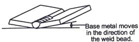
Distortion - Contraction of the weld metal during the welding that forces base metal to move.
Figure 48: Good Weld Bead Characteristics
 Fine Spatter
Figure 49: Excessive Spatter |
|
Possible Causes |
Corrective Actions |
Wire feed speed too high |
Select lower wire feed speed. |
Voltage too high |
Select lower voltage range. |
Electrode extension (stick-out) too long |
Use shorter electrode extension. |
Workpiece dirty |
Remove all grease, oil, moisture, rust, paint, undercoating, and dirt from work surface before welding. |
Insufficient shielding gas at welding arc. |
Increase flow of shielding gas at regulator/flowmeter and/ or prevent drafts near welding arc. |
Dirty welding wire |
Use clean, dry welding wire. Eliminate pickup of oil or lubricant on welding wire from feeder or liner. |
Figure 50: Porosity |
|
Possible Causes |
Corrective Actions |
Inadequate shielding gas coverage |
Check for proper gas flow rate. Remove spatter from gun nozzle. Check gas hoses for leaks. Eliminates drafts near welding arc. Place nozzle ¼ to ½ in (6-13 mm) form work piece. Hold gun near bead at the end of weld until molten metal solidifies. |
Wrong gas |
Use welding grade shielding gas; change to different gas. |
Dirty welding wire |
Use clean, dry welding wire. Eliminate pick up of oil or lubricant on welding wire from feeder or liner. |
Workpiece dirty |
Remove all grease, oil, moisture, rust, paint, coatings and dirt from work surface before welding. Use a more highly deoxidizing welding wire. |
Welding wire extends too far out of nozzle |
Be sure welding wire extends not more than ½ in (13mm) beyond nozzle. |
Porosity – Small cavities or holes resulting from gas pockets in weld metal.
Incomplete Fusion - Failure of weld metal to fuse completely with base metal or a preceding weld bead.
Excessive Penetration – weld metal melting through base metal and hanging underneath weld.
Possible Causes |
Corrective Actions |
Improper joint preparation |
Material too thick. Joint preparation and design must provide access to bottom of groove while maintaining proper welding wire extension and arc characteristics. |
Improper weld technique |
Maintain normal gun angle of 0 – 15 degrees to achieve maximum penetration. Keep arc on leading edge of weld puddle. Be sure welding wire extends not more than ½ in (13mm) beyond nozzle. |
Insufficient heat input |
Select higher wire feed speed and/or select higher voltage range. Reduce travel speed. |
Lack of Penetration – Shallow fusion between weld metal and base metal
Burn Through – weld metal melting completely through base metal resulting in holes where no metal remains.
Figure 54: Burn Through  |
|
Possible Causes |
Corrective Actions |
Excessive heat input |
Select lower voltage range and reduce wire feed speed. Increase and/or maintain steady travel speed. |
Waviness of bead –Weld metal that is not parallel and does not cover joint formed by base metal.
Figure 55: Waviness of Bead  |
|
Possible Causes |
Corrective Actions |
Welding wire extends too far out of nozzle |
Be sure welding wire extends not more than ½ in (13mm) beyond nozzle. |
Unsteady hand |
Support hand on solid surface or use two hands. |
10.5 Weld Testing and Inspection
Weld testing and inspection can be divided into two types. In non-destructive testing, the test samples are not destroyed in the process. In destructive testing, the test samples are destroyed in the process.
Non-Destructive Testing - Non-destructive testing of weld samples normally carried out using the following methods.
Macro Examination
This method uses a low power magnification to examine weld specimens which have been leveled, polished and etched to defect the following: lack of fusion, lack of penetration, porosity, oxide, inclusions and internal cracks.
Crack Detection
By using dye penetrant, surface defects in both, ferrous and non- ferrous metals may be detected. A solution of coloured dye is sprayed on to the weld and parent metal and allowed to soak. The dye is then washed off and the surface dried. A liquid developer is then sprayed on to the weld to give a uniform dry powder coating which is white in colour. The coloured dye oozes out of any crack in the weld into the white coating and can be seen in normal lighting conditions.
Magnetic Particle Method
Surface defects in mild steel and low-alloy steels may be revealed by this method. The test specimen is connected to a special power source. The magnetic test liquid is sprayed along the weld. The magnetic particles then collect along a line of crack when the current flows through the weld. Better test results are obtained if the surface of the weld has first been ground smooth. As these penetrants and magnetic test liquids give off harmful vapours, the work must be carried out under well ventilated conditions.
Ultrasonic Inspection
This method uses sound waves which are passed through the weld. They are transmitted as pulses by a probe connected to an ultrasonic test set. Defects reflect these pulses back to the probe through a flexible cable which is attached to the ultrasonic test set. Defects reflect these pulses back to the probe through a flexible cable which is attached to the ultrasonic test set, where it is displayed on an oscilloscope screen as deflections of a trace. These deflections measure the location and size of the defect. Grease is used between the probe and the work to improve sound transmission. Also light grinding of the weld or parent material surface to remove spatter may be required before testing.
Radiography
This method uses penetrating X-Rays or gamma rays which are passed through the weld and are recorded on photographic film held in a light proof container. When the film has been processed, any defect in the weld will show, as shadows in the photographic image. Only trained and radiation classified personnel may operate radiography equipment, as the equipment is extremely dangerous.
Visible Examination
This is normally carried out during and after welding and prior to any other non-destructive or destructive test being used. This visual check will usually determine the following:
Destructive Testing
Mechanical testing is a destructive procedure and therefore cannot be carried out on any component required for use. Representative
test samples produced under similar conditions to the in-service components, for example welding procedure tests, are normally used and accurate comparisons made.
The tests most frequently used to assess the properties of welded joints are as follows:
Tensile Test
This test can be used to assess the yield point, ultimate tensile strength and elongation percentage of the weld specimen. Failure usually occurs in the parent material; therefore exact measurements are not usually obtained for the weld itself, although in this case the ultimate tensile strength (UTS) of the weld is higher than that of the parent metal. Test specimens are cut from the designated area of the weld assembly, the edges are smoothed and the corners are radiused. If an elongation value is required, then two centre punch marks often 50mm apart are applied one on either side of the weld, this is called a gauge length. The test equipment can vary, but the basic principles are that two sets of vice jaws are used to clamp the specimen, hydraulic power is applied to force the jaws apart, and a dial calibrated in tones or newtons records the load. As the load increases, the dial registers the amount of applied load until fracture occurs.
Bend Test
Bend tests are carried out on butt welds and are used to determine the soundness of the weld zone. The test piece is the full thickness of the material, with the weld bead reinforcement dressed flush on both sides. It is common practice to take two specimens from the face and the other bent against the root. A bend test machine consists of a roller or former connected to a ram and operated hydraulically. Unless otherwise stated, the diameter of the former should be four times the weld specimen thickness. The specimen is placed on support rollers and the centre point of the former is brought into contact with the weld face or root. Pressure is then applied to bend the weld specimen through either 90 or 180 degrees.
11.0 MIG Brazing
As well as being in vehicle repair, this process is also used in vehicle production on some assembly lines as it offers increased speed and a smooth flat bead requiring little dressing after brazing. The MIG brazing process can be used with the traditional brazing filler materials of aluminium bronze, phosphor bronze and silicon bronze in the form of a continuous wire on a reel. With this process the choice of filler material and shielding gas is important if the necessary flat amounts of dressing would be required. The shielding gas used is normally pure argon. However, gases that are a mixture of helium and argon produce a more fluid weld pool, which again leads to a flatter bead than with argon. A 70 per cent argon and 30 per cent helium mix is generally preferred for thinner cosmetic panels, since the richer 80 per cent argon and 20 per cent helium mix can produce excessive penetration with an increased risk of distortion, although this can be used to advantage on thicker panel structures. The purpose of using this technology is to introduce the concept of “Crash Management”, which fulfil two roles in the event of an accident:
So that all of the benefits of the car body can be maintained even after accident repair, there are clear guidelines for body repair work. The newest and most significant aspect for the repair worker is MIG Brazing. MIG Brazing is recommended for welding on ultra high strength and the most important fact to remember is that gas shielded arc welding is not permitted on UHSS steels e.g. boron steel.
Principles
What are the technical differences between MIG Brazing and MIG/MAG welding with regard to processes? In terms of repair work, the technical differences in the process can be explained as follows:
MIG Brazing |
MIG/MAG welding |
A solder wire contained copper or Bronze is melted off. OPEL uses the CuSi3 (silicon-copper joint) solder wire on the car body. |
Steel based welding wires are melted off in this process, e.g. SG2 welding wire. |
Argon (Ar) is used as inert gas or mixtures of argon (Ar) and Helium (He) are used. Inert gases do not react with the molten bath. |
Metal Active Gas welding uses a mixture of carbon dioxide CO2 and argon as shielding gas in the majority of applications. The shielding gas reacts with the molten bath and is active. |
A temperature of approx 950ºC is required to melt off the CuSi3 solder wire. |
In MIG/MAG welding using steel wire the temperature is approx. 1500ºC - 1650ºC |
This leads to a temperature difference of 300ºC. This considerably lower processing temperature means that less heat is transferred to the weld region. If the MIG brazing process is carried out correctly, it results in only a slight change to the material properties of the base material in the joint area.
The steel materials in the body of most motor vehicles can no longer be welded using the standard MIG/MAG welding process. Previously used steels, which were familiar to car body manufacturers, have yield point strengths up to 300 N/mm² (MPA) steels (BH), which can be easily cold-formed in its supplied condition due to their strength as a result of the heat exposure due to their relatively low yield point. The steels reach their final strength as a result of the heat exposure during the car body coating process. The amount of high strength and ultra strength steels used in car body manufacture has increased.
High strength steels have yield points of between 220 and 550N/mm² (MPa) and ultra high steel strength steels, dual phase steel (DP) is use in the door sill area and the longitudinal rail of the frame. DP steel which is a ferritic fine-particle structural steel, with yield point values up to 400 N/mm (MPa) increases in strength during a cold forming in the pressure tool.
The reinforcing B pillar on the new Vectra C is manufactured from press hardened steel (PHS). This high strength heat treatable steel has a yield point of over 1000 N/mm (MPa), which is a value that is normally associated with bullet proof steels only. OPEL is a pioneer in developing uses for this steel, which had not previously been processed in this manner, in the manufacture of cars. Due to the joint characteristics of these fine-particle steels, the high degree of heat would change the joint structure when using conventional MIG/MAG welding. As a result, the behaviour of the components (crash, fatigue, strength) would be adversely affected. In technological terms: a soft annealing of the material occurs as a result of the high heat input during the MIG/MAG welding, which leads to a reduction in strength.
The joint technological principal behind Vectra C body production is the MIG brazing process and resistance spot weld. MIG brazing is used during the construction of a component that is susceptible to a collision. These components include, but are not limited to, the longitudinal beam of the frame and shock absorber mountings. These MIG – soldered seams are also important in terms of the
dynamic fatigue strength of the car body. The International Development Centre at Adam OPEL AG in Rüsselsheim has made this process compulsory for repair work in order to safeguard vehicle characteristics. In accordance with DIN ISO 9001/9002, all design drawings for repair work are labelled with reference to the OPEL/GM standard for MIG brazing and resistance spot welding. Furthermore, design drawings serve as the basis for service literature drafting in which repair regulations are stipulated.
12.0 Advantages of MIG Brazing
The advantage of a lower heat application in the weld has additional benefits:
The reduced heat input results in the following advantages:
Since there is no fusion of the base metal, it therefore has more in common with a brazed joint than a welded one.
Workshop conditions
As mentioned earlier, the material structure is altered in certain areas when using MIG/MAG welding, reducing the strength of the steel. For this reason MIG welding is not allowed on boron steel.
12.1 New Technology in Steels/Welding Methods
In the automotive industry the need to save weight while at the same time meeting increasingly severe crash test standards has led to the use of various types of high strength steels that conserve good ductility and formability. The high yield strength makes this material particularly suitable for anti-intrusion functions i.e. fender beams, door reinforcements and middle posts. The passenger cell anti-intrusion means they use steel with high yield strength on bumper frames to minimise the travel of impacts and protect the occupants.
Anti-intrusion front bumper beam made from high strength steel with yield strength of 550 N/mm² (mpa)
The use of steels like boron and martensite creates problems for the repair industry because when they are being manufactured the sheet steel is pre aluminised to protect the metal from oxidation and decarburisation during heat treatment. This also enhances the corrosion resistance after painting. The pre aluminized coating melts at temperatures of around 420ºc and vaporizes at 906ºc. This causes unfavourable effects on the welding process because regular MIG welding temperature of the welding arc is approx. 1450ºc. When you strike the arc the pre aluminised coating starts to vaporize releasing zinc vapors and oxides which can lead to defects such as pores and inadequate fusion in the weld. A solution to this problem is to use the MIG brazing process when welding pre aluminized steels such as boron and martensite. The reason for this is because MIG brazing uses copper silicon alloy welding wire (CUSI3) that has a relatively low melting point approx. 980ºc. At this temperature it does not cause the pre aluminized coating to vaporize. CUSI3 having a typical composition of 3% Silicon, 1% Manganese.
There are two other significant factors when welding or heat treating (UHSS). They are that, the lower critical limit of steel starts at 450ºc and at this temperature the grain structure does not change a lot when heated. However, when heated beyond the upper critical limit of 723ºc, caution should be taken because this changes the grain structure. Therefore it is important to use the correct procedure on the vehicle. Failure to do so could result in serious injury. Most vehicles have these steels in them now. The first car to have boron steel was the 02 Opel Vectra and the Ford S-Max has five different types of steel making up its body shell.
13.0 High Strength Steels
Most modern vehicles are constructed from a number of different steels, partly to obtain an optimised body (collision safety, rigidity, fuel economy, etc) and partly to make them light and as easy to repair as possible. Repair scenario, reliant on differing repair techniques.
Steels are divided into four groups according to their tensile and yield strength, that is to say the force necessary to bring about plastic deformation of the material.
Yield and Tensile Summary:
When welding on these high strength steels follow manufacturers recommendations, the sectioning and butt welding of EHS and UHS is not recommended as extreme heat alters the characteristics of the metal. A number of major car manufacturers are now using brazing fillets as a refinishing technique. On some unitised body structures, the manufacturers are also brazing joint surfaces to form reinforcement in a high stressed area. This is a highly skilled operation, the welder relying upon a capillary action to draw the molten brazing metal between the surfaces of the joint. This process is an alternative method to brazing with oxyacetylene gas.
MIG brazing produces a bright yellow filler metal, that can be easily dressed to produce a good finish. No fluxes are used for this particular method of brazing. The success of this operation was very much dependent upon the joints having relatively small clearances and surfaces free from contaminants.
13.1 Procedure Tips
On thin sheet steel and galvanised sheet use 0.8mm/1.0mm SIFMIG 968, keeping heat input to a minimum (approx 45-65). Select a shielding gas, which will maintain a stable arc, such as pure Argon. Pushing MIG torch (as conventional MIG welding) will ensure not too deep a penetration, avoiding burn through on thin sheet. If galvanised coating is thick, use dip transfer with a short arc.
14.0 MIG Welder Set-Up
Set up a MIG welder to include correct power gas flow rate and suitable filler wire diameter for MIG brazing.
The MIG brazing process is becoming increasingly common in the automotive industry, where especially corrosion security has become an important parameter. The process differs from MIG/MAG welding by the fact that the filler material fuses at a temperature of 960ºC.i In ordinary MIG/MAG the fusion temperature is approx1500º-1650ºC.
This means a not immaterial lowering of the induced heat and a considerably smaller risk of destructing the zinc coating. Zinc metals, however, at about 420ºC and vaporises at approx 910ºC which is an unfortunate property for MIG-brazing. This property also affects the welding process itself, since zinc starts vaporising as soon as the arc is established, and may lead to porosity, lack of fusion and instability of the arc. Therefore it is essential that MIG-brazing is carried out with equipment that reacts on the disadvantages caused by the zinc vapours.
The use of correct parameters ,shielding gas fillers will, however,, contribute to the creation of excellent groves and pores, even in case of thick zinc coatings. MIG-brazing will give you the following advantages.
The quality of MIG-brazing depends very much on the extent of zinc-vaporisation and oxides. There various drawbacks, such as pours in the weld, defects in the weld root (lack of fusion), cracking (zinc cracks), spatter, unstable arc and disconnected weld sequences.
The extent of disturbances during the brazing process depends in particular on the thickness of the zinc coating, but also the other alloys are important. If the zinc coatings are thicker than 15![]() m, the quantity of zinc vapour may result in unmistakeable instability in MIG-brazing. For that reason dip transfer or alternatively spray transfer with a short length of the arc are the most frequently used, which will help to achieve a reasonably stable arc.
m, the quantity of zinc vapour may result in unmistakeable instability in MIG-brazing. For that reason dip transfer or alternatively spray transfer with a short length of the arc are the most frequently used, which will help to achieve a reasonably stable arc.
Best of all, is to use pulse arc by use of an argon based shielding gas. This can give a controlled droplet pinch-off with one droplet per pulse. The pulse arc shows its value in particular in case of varying stick-out which usually results in increased spatter tendency in traditional dip transfer brazing.
To keep the zinc vaporisation at a minimum, it is necessary to MIG-braze with a small effect. For that reason it is important that the power source is capable of producing a stable arc, in particular in the low current ranges.
The result is a small heat input to the base material and reduced zinc vaporisation. This gives rise to a braze welding with a small number of pores. This is important to the ultimate stress of the braze welding, since the surface will usually be processed through grinding.
14.1 General Hints
Copper alloy MIG wires require ‘soft’ or formed wire feed drive rollers and a soft or Teflon type wire liner in the torch cable. If the welding machine has been used with steel MIG wire, ensure that steel particles are removed from the wire feed system. This is to avoid carbon contamination on the copper alloy wire.
14.2 Brazing Instructions:
Unlike traditional MIG/MAG welding, it is very important for the quality of the brazing to hold the torch in a pointing position. This allows the vaporised zinc gases to pass without disturbance of the arc. As a rule-of-thumb the following directions can be used:
Handling of the torch in MIG brazing:
Thickness of Plate |
Wire Dimension |
Arc Mode |
Current |
Voltage |
1.0mm |
1.0 |
Pulse Mode |
90-100 amp |
14-15V |
2.0 - 5.0mm |
1.0 |
Pulse Mode |
130-140 amp |
15-16V |
Overlap welds are often used in the automotive industry and to ensure an effective passage of the vaporised zinc gas it is an advantage to MIG braze with a small groove opening (0.5 – 1.0mm); this will facilitate the passage of the weld pool into the groove.
Thickness of Plate |
Wire Dimension |
Arc Mode |
Current |
Voltage |
1.0mm |
1.0 |
Pulse Mode |
70-80amp |
13-14 V |
2.0 – 3.0mm |
1.0 |
Pulse Mode |
100-140 amp |
14-17 V |
Fillet welds are used to some extent in the automotive industry. Since the MIG brazing process does not function with distinctly capillary effect, it would also in this case be an advantage to stitch with a 0.5-1.0mm groove. This will ensure fusion between the two plates. The torch should be held in a pointing position of approx. 60º in the welding direction.
Thickness of Plate |
Wire Dimension |
Arc Mode |
Current |
Voltage |
1.0mm |
1.0 |
Pulse Mode |
90-100 amp |
14-15 V |
2.0-5.0mm |
1.0 |
Pulse Mode |
110-130 amp |
15-17 V |
A butt weld is the most difficult groove to weld in, since full burn through is required, either as one-sided or two-sided welding. Common to both methods is the weld pool must run through the groove without fusion with the base material. Dependent on the thickness of plate, brazing should be carried out with a groove opening corresponding to the filler wire, which will allow the weld pool to pass through the groove and ‘wet’ the groove edges to a physical fusion with the braze filler material. This will ensure correct brazing. If the material gets too hot, or the base material fuses, the result is a ‘braze welding’ and too much burning of the zinc coating, which causes the protective effect to disappear.
15.0 Identify Weld Defects – MIG Brazing
Consequences:
What happens if someone uses the MIG/MAG welding process because they are uncertain of the procedure or because the MIG brazing equipment has not yet been purchased?
Uncertainty does not protect against claims for compensation. Specialist companies must get this message across and invest in the proper equipment.
How is the warranty affected if the work is carried out by an unauthorized, independent workshop?
The warranty granted by the manufacturer to the customer does not cover any defects to the vehicle that can be traced back to an independent workshop not using the MIG brazing process.
Is it possible to remove a MIG/MAG weld and replace it with a MIG brazed seam? Would this achieve the same technical condition as would have been the case if no MIG/MAG weld has been carried out?
No, the steel structure will have been altered as a result of the MIG/MAG welding process. Using grinding to remove the weld and brazing over the top would change nothing. The relevant component would have to be completely replaced in order to restore this “defective repair” to its original technical condition.
16.0 Hazards associated with welding uncoated and galvanised steel.
16.1 Filler Materials
Where a copper-based welding filler is used, the low melting point of copper and copper alloys means that only very limited fusion of the steel side takes place. SG CuSi 3 copper-based alloys are recommended for MIG brazing of galvanised coated panels on vehicles. Provided that the zinc layer is suitably thin (max 20![]() ), the welding quality of galvanised sheets can be influenced most clearly by way of the following process-engineering variables:
), the welding quality of galvanised sheets can be influenced most clearly by way of the following process-engineering variables:
16.2 Welding Power
With G3 Si 1 wires, the welder faces something of a dilemma. Higher power on galvanised light-gauge sheets can very easily lead to burn-through. If, on the other hand, the welder tries to reduce the heat input by welding at higher speed, there is a great increase in spattering, and more porosity. The answer is to weld at lower power than would be possible on coated sheets of the same thickness.
For MIG brazing in the pulsed arc, the droplet detachment can be set in such a way that only just enough energy is inputted to detach the droplet, without melting the base metal. This means less vaporisation (and less porosity).
Contact tube-to-work distance. This distance should be a maximum of 20mm or less. This has the following advantages:
Torch Manipulation
The welding torch should always be held in a slightly leading position. In this way, the arc does not burn directly on the zinc layer, but on the weld pool.
Position
In principle, it is possible to braze in all positions, although the PF position (vertical-up) should be avoided wherever possible because of it’s over high thermal input. Experience has shown that the best results are obtained in the PA (gravity), PB (horizontal) and PG (vertical-down) positions.
The following advantages will be found when bronze wires are used:
Care must be taken not to MIG-braze at excessive power, as in this case melting of the base metal takes place and copper may penetrate into the inter-granular boundaries.
The power source used for MIG-brazing must meet the following requirements:
16.3 Shielding Gas
As a rule, the recommended shielding gas is argon. However, trials have shown that CuSi 3 can also be welded with low O2 or CO2-content shielding gases. This makes the arc more stable.
17.0 MIG Brazing / Fabrication
17.1 Know Your Steels and their Yield.
Types of Steel |
Yield Strength |
Technical Information |
Mild Steel |
Less than 220 (MPa) |
Wings |
Deformable Steel |
220N/mm (MPa) |
Pedestrian Information |
(SS) Soft Steel |
220 N/mm (MPa) |
Soft Steel |
ZSTE 260 |
260N/mm (MPa) |
Soft-Medium |
ZSTE 300 |
300N/mm (MPa) |
Medium Strength |
(DD) Deep Drawn |
440N/mm (MPa) |
Easily Formed |
(IF) IF Steel |
440N/mm (MPa) |
Low Strength |
(IS) Isotropic Steel |
440N/mm (MPa) |
Low Strength 440Max |
(HSS) High Strength |
220-550N/mm (MPa) |
Medium Strength |
(DP) Dual Phase Steel |
450-1300/mm (MPa) |
Many Crystalline forms/combinations |
(EHS) Extra High Strength |
550-800N/mm (MPa) |
Extra High Strength |
(UHS) Ultra High Strength Steel |
800-1300/mm (MPa) |
Press Hardened Steel e.g. Manganese Boron |
(MS) Mertensite Steel |
1400N/mm (MPa) |
Excess Carbon For Hardness (Hardest Form) |
Summary
The perspective regarding intermediate and long-term development, and use of new car body materials and associated joining techniques (production and specialist repair)?
Source: http://local.ecollege.ie/Content/APPRENTICE/liu/vbr_notes/m1u3.doc
Web site to visit: http://local.ecollege.ie
Author of the text: indicated on the source document of the above text
If you are the author of the text above and you not agree to share your knowledge for teaching, research, scholarship (for fair use as indicated in the United States copyrigh low) please send us an e-mail and we will remove your text quickly. Fair use is a limitation and exception to the exclusive right granted by copyright law to the author of a creative work. In United States copyright law, fair use is a doctrine that permits limited use of copyrighted material without acquiring permission from the rights holders. Examples of fair use include commentary, search engines, criticism, news reporting, research, teaching, library archiving and scholarship. It provides for the legal, unlicensed citation or incorporation of copyrighted material in another author's work under a four-factor balancing test. (source: http://en.wikipedia.org/wiki/Fair_use)
The information of medicine and health contained in the site are of a general nature and purpose which is purely informative and for this reason may not replace in any case, the council of a doctor or a qualified entity legally to the profession.
The texts are the property of their respective authors and we thank them for giving us the opportunity to share for free to students, teachers and users of the Web their texts will used only for illustrative educational and scientific purposes only.
All the information in our site are given for nonprofit educational purposes