
Arc welding processes uses an electrical power supply to create and maintain an electric arc between an electrode and the base material to melt metals at the welding point. They can use either direct (DC) or alternating (AC) current, and consumable or non-consumable electrodes. The welding region is protected by some type of inert or semi-inert gas, known as a shielding gas.
The manual metal arc process occurs when two wires which form part of an electrical circuit are brought together and then pulled slowly apart, an electric spark is produced across their ends. This spark, or arc as it is called, has a temperature of up to 3,600°C. As the arc is confined to a very small area it can melt metal almost instantly. If one of these wires is connected to the job and the other to a wire rod or electrode, as it is usually called, the heat of the arc melts both the metal of the job and the point of the electrode. The molten metal from the electrode mixes with that from the job and forms the weld. It is important to realize that tiny globules of the molten metal from the electrode are forced through the arc (they do not fall by gravity). If this were not so it would be impossible to use this process for overhead welding.
To create the arc for welding, a voltage between 60 and 100 Volts is required to create the arc, but once it has been established, 20–40 Volts is required to maintain it. The following stages occur when creating an arc:
Manual metal arc power source and welding leads
There are two types of welding power source used to supply current for metal-arc welding.
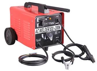
The AC power source
This power source takes its power directly from the main electricity supply. It uses a transformer to supply the correct voltage to suit the welding conditions. A special device in the transformer allows the current in the secondary coil to be adjusted. The primary coil is connected to the electricity power supply and the secondary coil is connected to the earth clamp and the electrode holder.
The DC power source
There are two types of DC welding plant in use:
The DC generator uses a motor (electric, petrol or diesel powered) to generate electricity. The generator provides DC current for the arc.
A Transformer-rectifier is basically a transformer with an electrical device for changing the alternating current into a direct current output. This device is known as a rectifier. The transformer-rectifier has the advantage that it can be made to supply AC or DC.
To supply the electrical energy necessary for arc welding processes, a number of different power supplies can be used. The most common classification is constant current power supplies and constant voltage power supplies. In arc welding, the voltage is directly related to the length of the arc, and the current is related to the amount of heat input. Constant current power supplies are most often used for manual welding processes such as gas tungsten arc welding and shielded metal arc welding, because they maintain a relatively constant current even as the voltage varies. This is important because in manual welding, it can be difficult to hold the electrode perfectly steady, and as a result, the arc length and thus voltage tend to fluctuate. Constant voltage power supplies hold the voltage constant and vary the current, and as a result, are most often used for automated welding processes such as gas metal arc welding, flux cored arc welding, and submerged arc welding. In these processes, arc length is kept constant, since any fluctuation in the distance between the wire and the base material is quickly rectified by a large change in current. For example, if the wire and the base material get too close, the current will rapidly increase, which in turn causes the heat to increase and the tip of the wire to melt, returning it to its original separation distance.
The type of current used in arc welding also plays an important role in welding. Consumable electrode processes such as shielded metal arc welding and gas metal arc welding generally use direct current, but the electrode can be charged either positively or negatively. In welding, the positively charged anode will have a greater heat concentration, and as a result, changing the polarity of the electrode has an impact on weld properties. If the electrode is positively charged, it will melt more quickly, increasing weld penetration and welding speed. Alternatively, a negatively charged electrode results in more shallow welds. Non-consumable electrode processes, such as gas tungsten arc welding, can use either type of direct current, as well as alternating current. However, with direct current, because the electrode only creates the arc and does not provide filler material, a positively charged electrode causes shallow welds, while a negatively charged electrode makes deeper welds. Alternating current rapidly moves between these two, resulting in medium-penetration welds. One disadvantage of AC, the fact that the arc must be re-ignited after every zero crossing, has been addressed with the invention of special power units that produce a square wave pattern instead of the normal sine wave, making rapid zero crossings possible and minimising the effects of the problem.
“Arc Blow” is encountered with D.C welding equipment. The arc is forced away from the weld point notably when welding in corners. The conductors carrying the current namely the welding lead from the set, and the return lead from the work piece are carrying current in opposite direction so that a repulsive magnetic force is set up which effects the D.C. Welding Arc.
This conditions occurs most when using currents above 200 or below 40 amps. The best method of connections are:
The purpose of the cables is to carry the current required for the arc. One cable ends at the earth clamp. The other goes to the electrode holder. It is important that the cables are not too small in diameter. Small cables may have too high a resistance and may overheat during the welding operation. Most cables contain many strands of fine copper wire. This enables them to carry the electric current and it makes them very flexible.
The electrode holder is an electrically insulated clamping device which holds the electrode. It is connected to one of the cables coming from the welding plant. The current passes from the cable through the electrode holder to the electrode.
This is connected to the other cable coming from the power plant. It is secured to the work by means of a screw clamp or a strong spring-operated clip.
The work is connected to the source of electrical supply (welding set). The electrode holder, held by the operator, is connected to the same source. The electric arc completes the circuit.
Set-Up for Manual Metal Arc Welding
The arc will not start until the electrode touches the work. This completes the circuit. When the electrode is lifted away slightly, and a gap appears once more, electricity passes across the gap using the lined-up atoms of (ionised) air as a conductor. The arc is stopped, or broken, by moving the electrode further away. Intense heat is developed; temperatures in manual metal arc welding measure up to 6000°C. The heat at the upper end of the arc melts the consumable electrode, while the heat at the lower end of the arc melts the parent metal (the metal being welded).
When welding the operator should observe all the general safe working procedures required for thermal processes, some specific to MMA welding are as follows:
Please refer to your instructor for site specific safety requirements before carrying out any welding procedures.
Safety Precautions
If the current value is too low the resulting weld has poor penetration, due to the lack of heating to create complete fusion. The weld filler metal tends to heap up on the surface of the plate without fusing to it and the arc has an unsteady sputtering sound.
Current too low
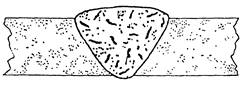
When the current value used is too high the electrode becomes red hot and a large amount of spatter takes place. This can result in blowholes being formed in the plate, excessive penetration resulting in weld metal beads on the underside of the plate, undercut along the edge of the weld and excessive oxidation and slag which is hard to remove. The arc has a fierce crackling sound.
Current too high
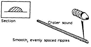
With the correct current the arc has a steady crackling sound. The weld formed has good penetration and is easily controlled.
Correct current
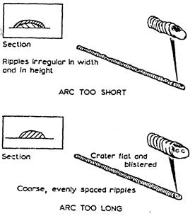
The arc length is the distance between the tip of the electrode and the surface of the weld pool. It should be approximately equal to the diameter of the wire core of the electrode being used. When this distance is correct the electrode metal is deposited in a steady stream of metal particles into the weld pool. If the arc length is reduced it becomes difficult to maintain the arc, due to the increase in welding current that takes place, and it can result in the electrode becoming welded to the weld pool. Also, if the arc length is increased the welding current is reduced, resulting in a poor weld being produced, and the protective gas shield produced from the electrode surrounding the weld pool cannot efficiently prohibit the formation of oxides, etc., in the weld.
Arc length
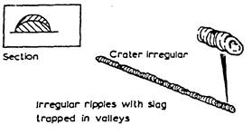
A fast rate of travel results in a thin deposit of the filler metal and can result in insufficient fusion of the filler metal with the base metal. The surface of the weld has elongated ripples and a porous crater.
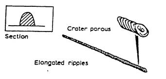
Speed of travel – too fast
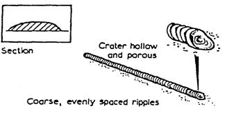
Too slow a rate of travel gives a wide thick deposit of the filler and it can allow the slag to flood the weld pool making it difficult to deposit the filler metal. The surface of the weld appears as coarse ripples and has a flat crater.
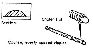
Speed of travel – too slow

When a piece of metal is heated in the atmosphere it combines with the oxygen and nitrogen to form oxides and nitrides which combine with the metal. If these were allowed to form in the weld it would result in a poor quality, weak and brittle weld. It is therefore necessary to protect the weld area from the air. This can be done either by surrounding the weld area by an inert gas or by the use of suitable fluxes. It is usual, with manual metal arc welding, to use coated electrodes. These electrodes consist of a metal core surrounded by a layer of suitable flux coating.
The six main functions of the electrode coating are as follows:
The method of classifying of electrodes in accordance with the American Welding Society (AWS) is based on the use of a Four-digit number, preceded by the letter ‘E’ for ‘Electrode’. The first two digits designate the minimum tensile strength of the weld metal (in 1,000 psi) in the as-welded condition. The third digit indicates the position in which the electrode is capable of making satisfactory welds. The fourth digit indicates the current to be used, and the type of flux coating.
For example, the classification of E6012 electrodes is derived as follows:
E = Metal arc welding electrode.
60 = Weld metal UTS 60,000 psi min.
1 = Usable in all positions.
2 = Rutile type coating: AC or DC negative.
The detail of the classification is shown below:
E 60xx As-welded deposit. UTS 60.000 psi min. for E 6010, E 6011,
E 6012, E 6013, E 6020, E 6027 UTS.
E 70xx As-welded deposit, UTS 70.000 psi min. for E 7014, E7015, E7016, E7018, E 7024 and E 7028.
The third and fourth digits indicate positional usability and flux coating types e.g.
Exx10 = High cellulose coating, bonded with sodium silicate, deeply penetrating, forceful, spray-type arc, thin, friable slag, all-positional. (Direct Current DC), electrode positive only.
Exx11 = Very similar to Exx10, but bonded with potassium silicate to permit use on AC or DC positive.
Exx12 = High rutile coating, bonded with sodium silicate. Quiet arc, medium penetration, all-positional, on (AC or DC) negative.
Electrodes for welding mild steel should be kept dry to avoid the possibility of porosity. They should be kept in the packet in which they came to ensure correct identification and to avoid damage to the coating.
They should not be bent to avoid breaking of the coating and subsequent contamination of the weld.
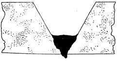
Lack of penetration is the failure of the filler metal to penetrate into the joint. It is caused by:
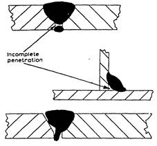
Lack of penetration
Lack of fusion is the failure of the filler metal to fuse with the parent metal. It is caused by:
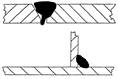
Lack of fusion
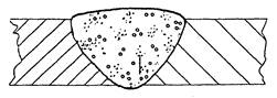
Porosity is a group of small holes throughout the weld metal. It is caused by the trapping of gas during the welding process, due to chemicals in the metal, dampness, or too rapid cooling of the weld.
Porosity
Slag inclusion is the entrapment of slag or other impurities in the weld. It is caused by the slag from previous runs not being cleaned away, or insufficient cleaning and preparation of the base metal before welding commences.
Slag inclusion
Undercuts are grooves or slots along the edges of the weld caused by:
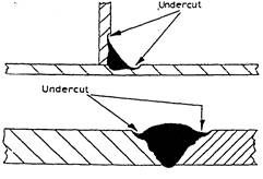
Undercut
Overlays consist of metal that has flowed on to the parent metal without fusing with it. The defect is caused by:
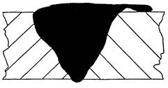
Overlay
Cracking is the formation of cracks either in the weld metal or the parent metal. It is caused by:
Crackling
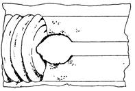
Blowholes are large holes in the weld caused by:
Blowholes
Burn through is the collapse of the weld pool due to:
Burn Through
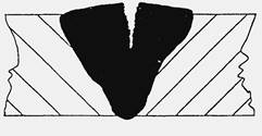
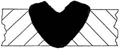
Excessive penetration is where the weld metal protrudes through the root of the weld. It is caused by:
Excessive Penetration
When a piece of metal is heated it expands and, on cooling down, it contracts. With welding and cutting processes the heating takes place over a localized area of the metal and expansion can only take place in that portion of the metal. The subsequent contraction that takes place on cooling can result in forces causing distortion or, even worse, cracking of the metal. When a weld bead is deposited on the joint between two plates, the molten metal passing through the arc is at a very high temperature. The arc melting the edges of the joint and the filler and base metal fuse together. As the arc moves across the joint the deposited bead starts to cool and considerable contraction forces are set up in the weld area.
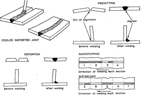
As the deposited metal was at a higher temperature than the parent metal it will contract more and also, since its volume is greater, there is a large volume of metal shrinkage. The result is distortion of the joint. The following are several ways of controlling the effect of distortion during welding; presetting; backstepping or stepwelding, jigging, and preheating. They are described and shown below:
Presetting
This entails setting the joint out of alignment prior to welding so that after contraction has taken place the joint is aligned.
Backstepping or Stepwelding
This entails welding the joint in short steps, ensuring that expansion and contraction zones are placed next to one another.
Jigging
This entails holding the metal being welded in a jig, restraining the distortion mechanically.
Preheating
This entails heating the metal to be welded prior to welding, and has the effect of allowing equal contraction to take place in both the weld and parent metal.
Distortion / Presetting / Backstepping / Skip-welding
Engineering drawings are descriptions of manufactured objects in terms of shape. surface, finish and material. In many industries it is customary to draw the shape of the component without indicating how that shape is achieved. The drawing is a description of a requirement produced by the designer for the instruction of the manufacturer. In theory, the manufacturer knows best how to produce an object with the resources he has. In practice, of course. the designer compromises and produces designs which are capable of production by the techniques ,of which he is aware. For example, a round hole can be drilled, bored or punched. and can be finished by reaming, but whichever method is used, the lines on the drawing are the same and whichever method is used, the material is not changed in its characteristics.
A welded joint offers a range of considerations which do not arise in other forms of manufacture. Firstly, there are far more techniques for making a welded joint than in many other manufacturing operations. This means that the designer has far less chance of foreseeing the manufacturer’s methods. Secondly, the properties and integrity of the joint will depend on the manner in which the weld is made Despite this, the designer can still indicate the type of joint he requires. provided that he is prepared to accept that he may not be able to completely define the joint in the earlier stages of a design.
In some industries it is customary for the manufacturer to produce shop drawings which contain details of weld preparations and reference to established welding procedures not shown in detail on the designer’s drawings. The range of British Standard symbols which can be used on a drawing to indicate a weld detail are described here.
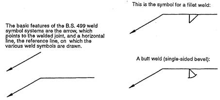
Basic B.S. 499 weld features
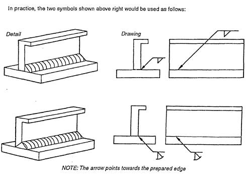
Basic B.S. 499 weld features applied
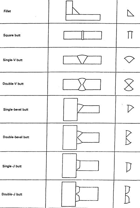
B.S weld symbols 1.
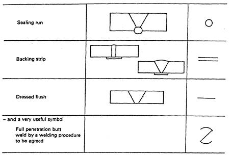
B.S weld symbols 2.
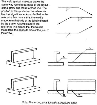
B.S weld symbols example 1
B.S weld symbols example 2.
Weld size can be indicated on the symbol. 6 mm fillet weld. The drawing must state whether a throat or leg dimension is quoted.
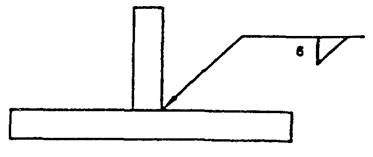
6mm fillet weld
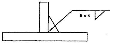
Unequal leg fillet weld. This must be defined by leg length. A diagram of weld ) shape is required here.
Unequal leg fillet weld
A diagram is not required here because the size of the members indicates the weld orientation.
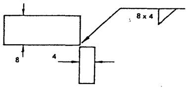
Size of the members
Information other than weld size may be written to the right of the symbol. The figure in brackets is the space length. 50 before (100) indicates that the weld is at the beginning. (100) 50 would indicate a space first then a weld although such an arrangement would not represent good practice.
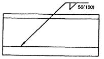
Information on side of the symbol
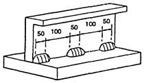
Intermittent welds
Source: http://local.ecollege.ie/Content/APPRENTICE/liu/pipefitting/word/M2_U3_Manual%20Metal%20Arc%20Welding.doc
Web site to visit: http://local.ecollege.ie
Author of the text: indicated on the source document of the above text
If you are the author of the text above and you not agree to share your knowledge for teaching, research, scholarship (for fair use as indicated in the United States copyrigh low) please send us an e-mail and we will remove your text quickly. Fair use is a limitation and exception to the exclusive right granted by copyright law to the author of a creative work. In United States copyright law, fair use is a doctrine that permits limited use of copyrighted material without acquiring permission from the rights holders. Examples of fair use include commentary, search engines, criticism, news reporting, research, teaching, library archiving and scholarship. It provides for the legal, unlicensed citation or incorporation of copyrighted material in another author's work under a four-factor balancing test. (source: http://en.wikipedia.org/wiki/Fair_use)
The information of medicine and health contained in the site are of a general nature and purpose which is purely informative and for this reason may not replace in any case, the council of a doctor or a qualified entity legally to the profession.
The texts are the property of their respective authors and we thank them for giving us the opportunity to share for free to students, teachers and users of the Web their texts will used only for illustrative educational and scientific purposes only.
All the information in our site are given for nonprofit educational purposes