
Chapter 3.
IHOS MODEL.
3.1. Introduction
The goal of this chapter is to present a comprehensive model for the IHOS (Integrated Heterodyne Optical System). The chapter provides an introduction to the MOEMS (Micro-Opto-Electro-Mechanical-System) modulator, the photodetector, and the amplifier.
First, we discuss the system electrical parameters. We model the signal and noise for the various components of the system. We introduce the background for the noise mechanisms of the silicon photodetector and the transresistance amplifier. In addition, we simulate the photodetector and amplifier stages in order to predict the signal and noise voltage spectral densities at the output of the system. Next, we provide the model for the MOEMS, which is used as the basis for the design chapter. Figure 3.1 illustrates the four stages that will be described in detail.
The novelty in modeling the entire system is based on the unique representation of different physical variables that describe the combined behavior of MOEMS, and semiconductor parameters into a single model that can be utilized as a design tool.
Thermal noise and shot noise are present mainly in the photo-detecting stages generally showing a uniform spectral distribution. Thermal noise is also present at the input of the amplifier and in the feedback network. The electronic system can be cooled down in order to reduce the thermal noise. Modulation prior to photodetection provides the most effective method to overcome the low-frequency noise (flicker noise) manifested in the subsequent stages. The low-frequency noise of the photodiode and amplifier stages can be overcome by modulating the input signal in the low kHz. A bandpass filter further improves the SNR as the system bandwidth is reduced to the desired frequencies of interest. Such filter can be implemented with a lock-in amplifier operating synchronously at the same frequency as the MOEMS modulator.
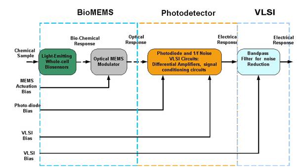
Figure 3.1: Integrate heterodyne optical system adapted for detection of light emitting whole-cell biosensors.
3.2. Noise in the Photodetection Stage
The photodetector stage is implemented by a photodiode in reverse bias connected to a transimpedance amplifier with a resistor and capacitor in the feedback loop. The feedback network is based on the parallel connection of the capacitor with the resistor, which provides frequency compensation. Figure 3.2 shows a schematic diagram of an amplifier with the integrated noise sources. The transresistance amplifier, however, also suffers from various types of noise mechanisms. We have used the noise model developed by Hamstra and Wendland [67]. Herein, we refer the reader to Appendix I for comprehensive discussion of the noise in photodiodes and amplifiers, and all corresponding definitions. In this chapter, we simply summarize the results.
The actual magnitude of the noise at the output of the amplifer can be calculated using the following expression:  (3.1) Where a1 is the transfer function of the amplifier for the input current noise due to the photodiode, inpd, and the input current noise of the amplifier, in; a2 is transfer function of the amplifier for an input voltage noise, en; and a3 is the transfer function due to the feedback network noise, in_f. The total output voltage noise is obtained by integrating over the entire system bandwidth (
![]() ).
).

Figure 3.2: Photodiode connected to a transresistance amplifier.
In order to calculate the SNR ratio, we formulate the ratio of the output voltage due to the photocurrent, ipd, that enjoys a specific operating frequency determined by the transmissive MOEMS modulator, and output noise voltage integrated over the desired frequency range. Such expression is given by:
 (3.2)
(3.2)
The bandpass filter can be implemented electronically using a standard filter that provides a selective bandwidth. Among the several options exist to implement a lock-in amplifier provides a very narrow bandwidth and a simple method to demodulate the signal. The selectivity of the bandpass filter allows to further reduce the noise. Furthermore, a MEMS filter can also be implemented in order to obtain a high-Q, several references can be found in [68,69,70,71,72]. The SNR is the figure that ultimately determines the performance of the system.
Next, we have simulated the noise contribution of each stage in order to predict the minimum detectable signal (MDS). In order to achieve this task, we simulated the noise of the photodetector and transresistance, using Matlab (Matlab Corporation, USA). Table 3.1 summarizes all the physical values used for the system. Figure 3.3 illustrates the noise sources for each stage. In this first model, we have neglected the noise contribution of the MOEMS modulator.

Figure 3.3: Block diagram of the IHOS including different noise source. Modulation is performed prior to photodetection. Noise is added in the photodiode and amplifier stages.
In order to estimate the noise magnitude it is necessary to integrate the total of the square voltage spectral density over the desired frequency range. A simple method to estimate the magnitude of the noise at the output of the amplifier is based on multiplying the noise equivalent bandwidth (NEB) by the magnitude of the voltage density at each frequency. In this way, it is possible to estimate the minimum detectable signal by dividing the output noise by the gain of the amplifier. Figure 3.4 shows minimum detectable signal (MDS) of the photocurrent as a function of the bandpass filter bandwidth, which was simulated as 25 mHz, 100 mHz, 1 Hz, 5 Hz, and 10 Hz. A lock-in amplifier can implement such narrow bandwidth.
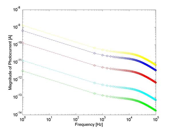
Figure 3.4: Calculated minimum detectable signal as a function of bandwidth. Green is 25 mHz, cyan is 100 mHz , Red is 1 Hz, Blue is 5 Hz, and Yellow is 10 Hz.
Table 3.1: Values of the photodiode and amplifier used for the simulations.
Stages |
Physical Variables |
Values |
Photodiode
|
Active Area (A) |
8 mm2 |
Operating Voltage (Vd) |
-1 V |
|
Saturation Current (Isat) |
10-11 A |
|
Quantum Efficiency (h) |
0.95 |
|
Parallel Resistance (Rd) |
10 GΩ |
|
Amplifier |
Capacitance (Cd) |
10-9 F |
Input Impedance (Rin) |
100 MΩ |
|
Input Capacitance (Cd) |
10-12 F |
|
Feedback Resistor (Rf) |
15 kΩ |
|
Feedback Capacitance (Cd) |
10-9 F |
|
Open loop Gain (Rf) |
15 kV/A |
|
Gain Product Bandwidth (ωH) |
10 MHz |
|
Amplifier Input Noise (en) |
10 |
|
Amplifier Input Noise (in) |
0.5 |
3.3. MOEMS Modulator
The MOEMS modulator is based on the design presented in the Chapter 4, which its schematics are shown here. The device is comprised of a comb-drive actuators connected to set of shutters that resonate in plane to allow transmissive modulation. The modulator is excited using a time dependent voltage signal ![]() , which is composed of a dc-offset signal and an ac-sinusoidal signal in such a way that
, which is composed of a dc-offset signal and an ac-sinusoidal signal in such a way that ![]() . Here
. Here ![]() denotes the "electrical" frequency of the electrical signal applied to the transducer as the excitation. Since the mechanical force produced by the comb-drive-based transducer is proportional to the square of the voltage, the transducer is characterized by the following force-voltage relation:
denotes the "electrical" frequency of the electrical signal applied to the transducer as the excitation. Since the mechanical force produced by the comb-drive-based transducer is proportional to the square of the voltage, the transducer is characterized by the following force-voltage relation:
(3.3)
Where ![]() represents the permittivity of the free space,
represents the permittivity of the free space, ![]() represents the height of the actuator, d is the gap between the comb fingers, and
represents the height of the actuator, d is the gap between the comb fingers, and ![]() is number of combs. One observes that as the electro-static transducer is driven by a single frequency electrical harmonic signal, the mechanical force, which is related to the voltage squared, is produced at two frequency scales: a. the excitation frequency and b. twice this frequency.
is number of combs. One observes that as the electro-static transducer is driven by a single frequency electrical harmonic signal, the mechanical force, which is related to the voltage squared, is produced at two frequency scales: a. the excitation frequency and b. twice this frequency.
The mechanical dynamic behavior of the modulator under harmonic excitation is described using a simplest one degree of freedom model:
![]() (3.4)
(3.4)
Where ![]() are the effective mass of the modulator, the total suspension stiffness in the stroke direction (axial displacement), and the damping coefficient (the typical value is 1.86.10-5 [N.S/m2]), respectively.
are the effective mass of the modulator, the total suspension stiffness in the stroke direction (axial displacement), and the damping coefficient (the typical value is 1.86.10-5 [N.S/m2]), respectively. ![]() is the amplitude of the excitation force; an example for the calculation of the effective mass of a comb-drive actuator and stiffness of the folded suspension. The steady state solution of Equation (2) can be written in the form [73]:
is the amplitude of the excitation force; an example for the calculation of the effective mass of a comb-drive actuator and stiffness of the folded suspension. The steady state solution of Equation (2) can be written in the form [73]:
![]() (3.5)
(3.5)
where
![]() , (3.6)
, (3.6)
is the amplitude, and
 (3.7)
(3.7)
is the phase angle. Here, ![]() is the "mechanical" natural frequency of the modulator and
is the "mechanical" natural frequency of the modulator and ![]() is the Q-factor. Substituting Equation (1) for the mechanical force into Equation (2) and taking into account Equations (3)-(5), we obtain the steady-state response of the modulator:
is the Q-factor. Substituting Equation (1) for the mechanical force into Equation (2) and taking into account Equations (3)-(5), we obtain the steady-state response of the modulator:
( 3.8 ) ,![]()
where
![]() (3.9)
(3.9)
is the static displacement,
( 3.10 ) ,![]()
( 3.11 ) , 
and
![]() (3.12)
(3.12)
The first mechanical scale occurs at the electrical signal frequency, ![]() , while the second one occurs at twice that frequency,
, while the second one occurs at twice that frequency, ![]() . As a result, the resonant excitation can be achieved as the device is driven by an electrical harmonic signal at half damped resonant frequency of the modulator, i.e.
. As a result, the resonant excitation can be achieved as the device is driven by an electrical harmonic signal at half damped resonant frequency of the modulator, i.e. ![]() , as well as at the damped resonant frequency itself, i.e.
, as well as at the damped resonant frequency itself, i.e. ![]() . In the former case, the mechanical response frequency differs significantly from the frequency of the electrical signal. The effective mass of such comb-drive actuator can be calculated according to the following expression [74]:
. In the former case, the mechanical response frequency differs significantly from the frequency of the electrical signal. The effective mass of such comb-drive actuator can be calculated according to the following expression [74]:
![]() (3.13)
(3.13)
Where mshuttle is the mass of the actuators, shutters and moving portion of the actuators; mbeam is the mass of a single beam of the folded flexure; mtruss is the mass of the truss of the folded suspension (typical design values are described in the subsequent in Chapter 4). The suspension stiffness can be calculated from the expression of a folded flexure [75]:
![]()
![]() (3.14)
(3.14)
where i is the total number of spring structures (generally taken in pairs), and b and l are the height and length of the folded-flexure beam, E is the Young’s modulus of silicon (the value is taken as 169 GPa).If we take into account that the MOEMS design is comprised of either 8 or 10 springs (the reader is referred to Chapter 5), then the natural frequency of the system can then be calculated as:
![]() (3.15)
(3.15)
3.4. Photodetection of Modulated Signal
As described earlier, the mechanical response of the device enjoys two main frequency scales. The first one occurs at the frequency of electrical excitation,![]() , whereas the second one occurs at twice that frequency,
, whereas the second one occurs at twice that frequency, ![]() . Figure 3.5 shows the cross-section of MOEMS modulator, where the shutters are driven by the actuators over the etched cavities that act as optical vias. Given this configuration, the frequency of the photodetected signal doubles the mechanical frequency. Therefore, the photodetected signal enjoys two main spectral components that occur at twice the electrical excitation frequency,
. Figure 3.5 shows the cross-section of MOEMS modulator, where the shutters are driven by the actuators over the etched cavities that act as optical vias. Given this configuration, the frequency of the photodetected signal doubles the mechanical frequency. Therefore, the photodetected signal enjoys two main spectral components that occur at twice the electrical excitation frequency,![]() , and at four times the electrical excitation frequency,
, and at four times the electrical excitation frequency, ![]() . Figure 3.6 shows a schematic representation of the frequency response of the modulated signal. Note that the arrows represent the Fourier components for the frequency spectrum of the electrical, mechanical, and optical responses.
. Figure 3.6 shows a schematic representation of the frequency response of the modulated signal. Note that the arrows represent the Fourier components for the frequency spectrum of the electrical, mechanical, and optical responses.
As the active area of a photodiode is exposed to a photon-flux, the current due to photon-generation is defined as:
![]() (3.16)
(3.16)
where Φ is the incident photon-flux [photons/sec-cm2], η is the quantum efficiency (i.e. 0.9), q is the electron charge, A is the active area of the photodiode. Since the active area of the photodiode is shuttered periodically as described by Equations 6-7, the photodetected signal varies as a function of time.
As discussed later in Chapter 4, the design of the MOEMS modualtator is comprised of either 20 or 40 shutters. Hence, the photodetected signal can be calculated from the following expression:
![]() (3.17)
(3.17)
Where Ls is the length of the shutters, u is the number of shutters. We have assumed that the displacement magnitude of the shutters is 50 µm, which is exactly the width of the optical vias. At an excitation frequency of half resonance, the photodetected signal can be expressed as follows:
![]() (3.18)
(3.18) ![]()
In this expression we disregarded the phase since it is not relevant for measuring bioluminescence from whole-cell biosensors.
Figure 3.5: Cross section of shutter configuration showing the input and output fluxes.
Amplitude
(Arbitrary Units)
Source: http://web.mit.edu/nelman/Public/Chapter_3FA.doc
Web site to visit: http://web.mit.edu/
Author of the text: indicated on the source document of the above text
If you are the author of the text above and you not agree to share your knowledge for teaching, research, scholarship (for fair use as indicated in the United States copyrigh low) please send us an e-mail and we will remove your text quickly. Fair use is a limitation and exception to the exclusive right granted by copyright law to the author of a creative work. In United States copyright law, fair use is a doctrine that permits limited use of copyrighted material without acquiring permission from the rights holders. Examples of fair use include commentary, search engines, criticism, news reporting, research, teaching, library archiving and scholarship. It provides for the legal, unlicensed citation or incorporation of copyrighted material in another author's work under a four-factor balancing test. (source: http://en.wikipedia.org/wiki/Fair_use)
The information of medicine and health contained in the site are of a general nature and purpose which is purely informative and for this reason may not replace in any case, the council of a doctor or a qualified entity legally to the profession.
The texts are the property of their respective authors and we thank them for giving us the opportunity to share for free to students, teachers and users of the Web their texts will used only for illustrative educational and scientific purposes only.
All the information in our site are given for nonprofit educational purposes