
Shoulders
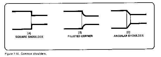
Frequently, it will be necessary to machine work that has two or more diameters in its length. The abrupt step, or meeting place, of the two diameters is called a shoulder. The workpiece may be mounted in a chuck, collet, or mandrel, or between centers as in straight turning. Shoulders are turned, or formed, to various shapes to suit the requirements of a particular part. Shoulders are machined to add strength for parts that are to be fitted together, make a corner, or improve the appearance of a part. The three common shoulders are the square, the filleted, and the angular shoulder (Figure 7-50).
Square shoulders are used on work that is not subject to excessive strain at the corners. This shape provides a flat clamping surface and permits parts to be fitted squarely together. There are many different ways to accurately machine a square shoulder. One method is to use a parting tool bit to locate and cut to depth the position of the shoulder. Straight-turning the diameter down to the desired size is then the same as normal straight turning. Another method to machine a square shoulder is to rough out the shoulder slightly oversize with a round-nosed tool bit, and then finish square the shoulders to size with a side-finishing tool bit. Both of these methods are fine for most work, but may be too time-consuming for precise jobs. Shoulders can be machined quickly and accurately by using one type of tool bit that is ground and angled to straight turn and face in one operation (Figure 7-51).
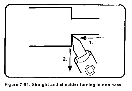
Set up the micrometer carriage stop to align the shoulder dimension; then, in one pass of the tool bit, feed the tool bit left to turn the smaller diameter until contact is made with the carriage stop. Change the direction to feed out from center and face the shoulder out to the edge of the workpiece. The lathe micrometer stop measures the length of the shoulder and provides for a stop or reference for the tool bit. Shoulder turning in this manner can be accomplished with a few roughing cuts and a finishing cut.
Filleted Shoulders
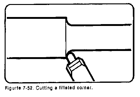
Filleted shoulders or corners, are rounded to be used on parts which require additional strength at the shoulder. These shoulders are machined with a round-nose tool bit or a specially formed tool bit (Figure 7-52). This type of shoulder can be turned and formed in the same manner as square shoulders. Filleted corners are commonly cut to double-sided shoulders (see Undercuts).
Angular Shoulders
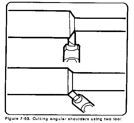
Angular shoulders although not as common as filleted shoulders, are sometimes used to give additional strength to corners, to eliminate sharp corners, and to add to the appearance of the work. Angular shoulders do not have all the strength of filleted corners but are more economical to produce due to the simpler cutting tools. These shoulders are turned in the same manner as square shoulders by using a side turning tool set at the desired angle of the shoulder, or with a square-nosed tool set straight into the work (Figure 7-53).
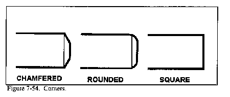
Corners
Corners are turned on the edges of work to break down sharp edges and to add to the general appearance of the work. Common types of corners are chamfered, rounded, and square (Figure 7-54). Chamfered (or angular) corners may be turned with the side of a turning tool or the end of a square tool bit, as in angular shoulder turning. Round corners are produced by turning a small radius on the ends of the work. The radius may be formed by hand manipulation of the cross slide and carriage using a turning tool. An easier method is to use a tool bit specifically ground for the shape of the desired corner. Still another method is to file the radius with a standard file. A square corner is simply what is left when making a shoulder, and no machining is needed.
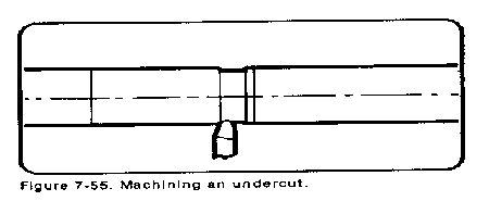
Undercuts
Undercuts are the reductions in diameter machined onto the center portion of workpieces (Figure 7-55) to lighten the piece or to reduce an area of the part for special reasons, such as holding an oil seal ring. Some tools, such as drills and reamers, require a reduction in diameter at the ends of the flutes to provide clearance or runout for a milling cutter or grinding wheel. Reducing the diameter of a shaft or workpiece at the center with filleted shoulders at each end may be accomplished by the use of a round-nosed turning tool bit. This tool bit may or may not have a side rake angle, depending on how much machining needs to be done. A tool bit without any side rake is best when machining in either direction. Undercutting is done by feeding the tool bit into the workpiece while moving the carriage back and forth slightly. This prevents gouging and chatter occurring on the work surface.
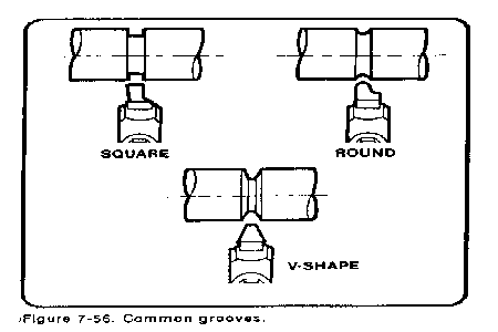
Grooves
Grooving (or necking) is the process of turning a groove or furrow on a cylinder, shaft, or workpiece. The shape of the tool and the depth to which it is fed into the work govern the shape and size of the groove. The types of grooves most commonly used are square, round, and V-shaped (Figure 7-56). Square and round grooves are frequently cut on work to provide a space for tool runout during subsequent machining operations, such as threading or knurling. These grooves also provide a clearance for assembly of different parts. The V-shaped groove is used extensively on step pulleys made to fit a V-type belt. The grooving tool is a type of forming tool. It is ground without side or back rake angles and set to the work at center height with a minimum of overhang. The side and end relief angles are generally somewhat less than for turning tools.
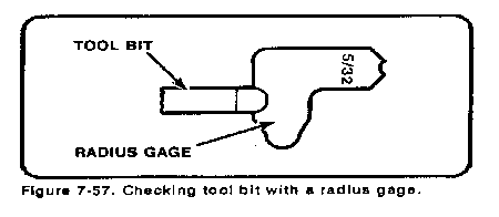
In order to cut a round groove of a definite radius on a cylindrical surface, the tool bit must be ground to fit the proper radius gage (Figure 7-57). Small V-grooves may be machined by using a form tool ground to size or just slightly undersize. Large V-grooves may be machined with the compound rest by finishing each side separately at the desired angle. This method reduces tool bit and work contact area, thus reducing chatter, gouging, and tearing. Since the cutting surface of the tool bit is generally broad, the cutting speed must be slower than that used for general turning. A good guide is to use half of the speed recommended for normal turning. The depth of the groove, or the diameter of the undercut, may be checked by using outside calipers or by using two wires and an outside micrometer (Figure 7-58).
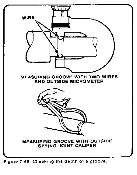
When a micrometer and two wires are used, the micrometer reading is equal to the measured diameter of the groove plus two wire diameters.
To calculate measurement over the wires, use the following formula:
Measurement = Outside Diameter + (2 x wires) - 2 x radius).
Parting
Parting is the process of cutting off a piece of stock while it is being held in the lathe. This process uses a specially shaped tool bit with a cutting edge similar to that of a square-nosed tool bit. When parting, be sure to use plenty of coolant, such as a sulfurized cutting oil (machine cast iron dry). Parting tools normally have a 5° side rake and no back rake angles. The blades are sharpened by grinding the ends only. Parting is used to cut off stock, such as tubing, that is impractical to saw off with a power hacksaw.
Parting is also used to cut off work after other machining operations have been completed (Figure 7-59). Parting tools can be of the forged type, inserted blade type, or ground from a standard tool blank. In order for the tool to have maximum strength, the length of the cutting portion of the blade should extend only enough to be slightly longer than half of the workpiece diameter (able to reach the center of the work). Never attempt to part while the work is mounted between centers.
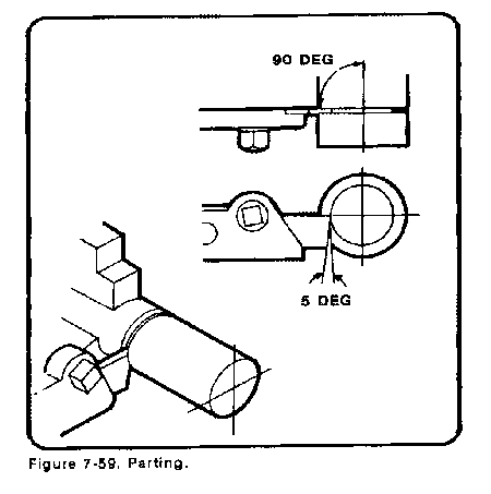
Work that is to be parted should be held rigidly in a chuck or collet, with the area to be parted as close to the holding device as possible. Always make the parting cut at a right angle to the centerline of the work. Feed the tool bit into the revolving work with the cross slide until the tool completely severs the work. Speeds for parting should be about half that used for straight turning. Feeds should be light but continuous. If chatter occurs, decrease the feed and speed, and check for loose lathe parts or a loose setup. The parting tool should be positioned at center height unless cutting a piece that is over 1-inch thick. Thick pieces should have the cutting tool just slightly above center to account for the stronger torque involved in parting. The length of the portion to be cut off can be measured by using the micrometer carriage stop or by using layout lines scribed on the workpiece. Always have the carriage locked down to the bed to reduce vibration and chatter. Never try to catch the cutoff part in the hand; it will be hot and could burn.
Occasionally, a radius or irregular shape must be machined on the lathe. Form turning is the process of machining radii and these irregular shapes. The method used to form-turn will depend on the size and shape of the object, the accuracy desired, the time allowed, and the number of pieces that need to be formed. Of the several ways to form-turn, using a form turning tool that is ground to the shape of the desired radius is the most common. Other common methods are using hand manipulation and filing, using a template and following rod, or using the compound rest and tool to pivot and cut. Two radii are cut in form turning, concave and convex. A concave radius curves inward and a convex radius curves outward.
Forming a Radius Using a Form Turning Tool
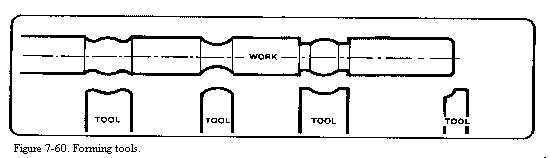
Using a form turning tool to cut a radius is a way to form small radii and contours that will fit the shape of the tool. Forming tools can be ground to any desired shape or contour (Figure 7-60), with the only requirements being that the proper relief and rake angles must be ground into the tool's shape. The most practical use of the ground forming tool is in machining several duplicate pieces, since the machining of one or two pieces will not warrant the time spent on grinding the form tool. Use the proper radius gage to check for correct fit. A forming tool has a lot of contact with the work surface, which can result in vibration and chatter. Slow the speed, increase the feed, and tighten the work setup if these problems occur.
Forming a Radius Using Hand Manipulation
Hand manipulation, or free hand, is the most difficult method of form turning to master. The cutting tool moves on an irregular path as the carriage and cross slide are simultaneously manipulated by hand. The desired form is achieved by watching the tool as it cuts and making small adjustments in the movement of the carriage and cross slide. Normally, the right hand works the cross feed movement while the left hand works the carriage movement. The accuracy of the radius depends on the skill of the operator. After the approximate radius is formed, the workpiece is filed and polished to a finished dimension.
Forming a Radius Using a Template
To use a template with a follower rod to form a radius, a full scale form of the work is laid out and cut from thin sheet metal. This form is then attached to the cross slide in such a way that the cutting tool will follow the template. The accuracy of the template will determine the accuracy of the workpiece. Each lathe model has a cross slide and carriage that are slightly different from one another, but they all operate in basically the same way. A mounting bracket must be fabricated to hold the template to allow the cutting tool to follow its shape. This mounting bracket can be utilized for several different operations, but should be sturdy enough for holding clamps and templates. The mounting bracket must be positioned on the carriage to allow for a follower (that is attached to the cross slide) to contact the template and guide the cutting tool. For this operation, the cross slide must be disconnected from the cross feed screw and hand pressure applied to hold the cross slide against the follower and template. Rough-cut the form to the approximate shape before disconnecting the cross feed screw. This way, a finish cut is all that is required while applying hand pressure to the cross slide. Some filing may be needed to completely finish the work to dimension.
Forming a Radius Using the Compound Rest
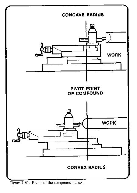
To use the compound rest and tool to pivot and cut (Figure 7-61), the compound rest bolts must be loosened to allow the compound rest to swivel. When using this method, the compound rest and tool are swung from side to side in an arc. The desired radius is formed by feeding the tool in or out with the compound slide. The pivot point is the center swivel point of the compound rest. A concave radius can be turned by positioning the tool in front of the pivot point, while a convex radius can be turned by placing the tool behind the pivot point. Use the micrometer carriage stop to measure precision depths of different radii.
Source: http://faculty.ksu.edu.sa/hossainy/Book1/Chapter%207.doc
Web site to visit:http://faculty.ksu.edu.sa
Author of the text: indicated on the source document of the above text
If you are the author of the text above and you not agree to share your knowledge for teaching, research, scholarship (for fair use as indicated in the United States copyrigh low) please send us an e-mail and we will remove your text quickly. Fair use is a limitation and exception to the exclusive right granted by copyright law to the author of a creative work. In United States copyright law, fair use is a doctrine that permits limited use of copyrighted material without acquiring permission from the rights holders. Examples of fair use include commentary, search engines, criticism, news reporting, research, teaching, library archiving and scholarship. It provides for the legal, unlicensed citation or incorporation of copyrighted material in another author's work under a four-factor balancing test. (source: http://en.wikipedia.org/wiki/Fair_use)
The information of medicine and health contained in the site are of a general nature and purpose which is purely informative and for this reason may not replace in any case, the council of a doctor or a qualified entity legally to the profession.
The texts are the property of their respective authors and we thank them for giving us the opportunity to share for free to students, teachers and users of the Web their texts will used only for illustrative educational and scientific purposes only.
All the information in our site are given for nonprofit educational purposes