
Edited by Kee-Rong Wu
7.1 Prospects in Medium-Speed Diesel Engines
7.1.1 Merits of Diesel Engines and Gas Turbine in Marine Propulsion
This session will concentrates on diesel engines for cruise vessel applications with a total power requirement of approx. 60 MW each installation. A typical diesel-electric drive with five medium-speed diesel engines will be compared with the 58 MW COGES (Combined Gas Turbine and Steam Turbine Integrated Electric Drive System) [7.1].
In summer 2000, Celebrity Cruises' gas turbine-driven cruising vessel Millennium made her maiden voyage. The 91000 Ton vessel with a Pax capacity of 1950 (lower berth) denotes a technological shift in cruise ship design, primarily because she is the first cruise ship powered by a pure gas turbine plant. Apart from this, the ship has the biggest azimuth pods ever built (two Mermaid pods of 19.5 MW each). Currently there are three further cruise ships of this series under construction. This certainly is a milestone for gas turbine movers, the more so as four further new Vantage-class cruise ships for Royal Caribbean International (RCI) are also specified with turbine-based propulsion plants. Each plant consists of two General Electric LM2500+ aero-derived gas turbines of 25 MW each and an 8 MW back-pressure steam turbine. The steam turbine uses steam from the boilers fired by waste-heat from the gas turbines to generate additional electrical power. Depending on the amount of steam required for onboard services, the complete COGES power plant is expected to achieve a combined-cycle efficiency of between 45 and 50%. This system will provide for all onboard power arrangements, such as propulsion, heating, cooling, lighting, ventilation, kitchen and laundry. However, with about 97% of all existing sea-going ships propelled by two and four-stroke diesel engines (Fig. 7.1) due to its comparably high thermal efficiency (Fig. 7.2), it seems their manufacturers have so far not seriously been affected by gas turbines in most of their traditional market areas.
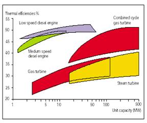
Fig. 7.2: Power efficiency comparison at ISO 3046 [7.1]
In general, diesel engines posses lower initial costs, fuel economy, weight and size as comparing with gas turbine’s environmental friendliness showing Fig. 7.3 and 7.4. The detail comparison will be described in followings.
7.1.1.1 Weight and size
Gas turbines are known to generate lots of power while offering less space and weight than a diesel engine of the same output. The diesel engine's size and heavy mass is an undisputable disadvantage in many applications. However in the new Panamax-sized cruise ships with an increased number of decks but unchanged width, much weight is needed in the bottom of a ship for stability purposes, so the value of the weight savings by gas turbines must not be over emphasized. In order to decrease the vertical center of gravity, this weight deficiency could be compensated by additional fresh water or fuel tanks. Another option is to slightly decrease the main deck height or draught of the vessel. However, all of this would necessitate a new ship design, excluding the use of a common hull form for either diesel engines or gas turbines that would be highly beneficial in order to cut costs. As regards the space savings of gas turbines, this potential cannot be fully utilized: Gas turbines have approx. 15% larger air intake and exhaust ducts as comparable diesel engines and their starting devices also occupy much space. Onboard cruising vessels with two gas turbines as prime movers, necessary provisions for a rapid replacement of a gas turbine (or at least its gas generator) within a few hours, with the vessel at sea and underway, occupies extra space. The engine room has to be designed with sufficient free space and all the necessary provisions and equipment for this job, including storage space for a complete spare gas turbine. Finally, plant availability and safety considerations make at least one or two additional diesel engine gensets mandatory to satisfy low power requirements difficult to cover with a gas turbine and as emergency generator. This does not only restrict the freed space further, but also increases first costs, operating costs and maintenance costs.
7.1.1.2 First and maintenance costs
Contrary to weight and size, first costs and maintenance costs are lower for the diesel solution, although first costs might be more a political concession. As regards maintenance, RCI has signed a 10 year repair and maintenance contract with General Electric for the vessels' LM2500+ gas turbines at a cost of 3 $/MW h. The maintenance cost summary of a multi-engine Diesel-electric gives a lower figure.
7.1.1.3 Fuel and operating costs
As indicated in Fig. 7.2, Diesel engines enjoy further benefits such as lower fuel prices, lower fuel consumption rates at all loads and therefore lower carbon dioxide emission and better load acceptance as well as quicker start-up times after a night stop. For instance, after a night stop, a gas turbine in simple-cycle mode needs 30 minutes until full load is reached, a diesel engine in the same situation less than 5 minutes.
7.1.1.4 Vibration, noise and lube oil consumption
As regards vibration and noise, multiple cylinder reciprocating engines with their intermittent combustion are at a disadvantage, although sometimes the real differences are exaggerated or erroneously interpreted. By direct-resilient mounting of Diesel engines, their structure-borne vibration transmitted into a ship foundation is reduced to a level of approximate below 50 dB at frequencies of above 1000 Hz. Although resiliently seated gas turbines might reach still lower values, design measures aiming at an even further decrease in diesel engines' structure borne noise can be omitted as long as the requirements regarding vibration in the cabins are met.
Unexpectedly the new-building Millennium experienced vibration problems in some areas of the ship under special sea conditions likely to occur in the Caribbean during the windy winter season. The ship had to be dry-docked for technical modifications earlier than planned, following its arrival in New York in November 2000.
Air-borne engine room noise of gas turbines is claimed to be less than 85 dB(A), whereas the noise emission of a MAN B&W large-bore medium-speed diesel engine varies between 102 and 108 dB(A) at full load. The main reason for this difference is that marine gas turbines are installed in acoustically insulated enclosures whereas the noise level for free-standing diesel engines is measured without any sound-attenuating encapsulation or lagging. Engine machine rooms are not among the places where passengers onboard usually spend their leisure time. Therefore the lower running noise of gas turbines is not of major importance: outside of the machine room, the diesel engines can be considered to be encapsulated as well.
The specific lube oil consumption of modern gas turbines is typically only 1% of the diesel engines' figure, but high priced synthetic lubes have to be used in comparison to the low-priced mineral oils for the Diesel engines. The annual lube oil costs of gas turbines are only about 6% of that of diesel engines. It has to be pointed out that this merit is of minor importance, since lube oil costs hardly affect the total operating costs.
The real advantage of the gas turbine is its eco-friendliness as far as SOx and NOx (not CO2) emissions are concerned. SOx emission of gas turbines is close to zero because they burn basically sulfur-free fuel (MGO typically contains only about 0.3 % sulfur, HFO for diesel engines up to 4.5%). If (higher-priced) low-sulfur or sulfur-free marine diesel oils would be used for diesel engines, there wouldn't be a SOx problem with them either. NOx emission levels of modern marine gas turbines and diesel engines are listed in Fig. 7.4. There is no basic technical restriction in decreasing diesel engines NOx emission down to a level of 2 g/kWh by adopting SCR based exhaust-gas cleaning. All today's serial NOx optimized marine diesel engines have to meet IMO NOx restrictions for international shipping valid for new ships (achieved by engine -internal measures). By direct injection of water into the cylinder or by adopting water-fuel emulsification, a similar NOx emission level as with today's standard marine gas turbines without water injection is achieved. The test results of a MAN B&W 6L48/60 engine in February 2000: a NOx cycle value of 7.7 g/kWh and a fuel consumption rate still within tolerance (5%) was measured. This is 40% below the NOx limit set by the IMO. This result was achieved with only 15% water in the water-fuel emulsion and a slightly retarded injection below 80% engine load [7.1].
7.1.1.5 Efficiency
Figure 7.2 shows the achievable overall efficiency level of today's prime movers. Large-bore medium-speed engines reach up to 47% in simple-cycle operation and low-speed diesel engines even up to 51%. With smaller engines the difference in efficiency and in fuel consumption between diesel engines and gas turbines increases considerably. Figure 7.2 is indicative of the high efficiency level that combined-cycle gas turbines of high unit output (above 50 MW) reach today. Up to now there are only few diesel combined-cycle (DCC) installations in operation. Their number will increase in future although this technology will increase the diesel’s efficiency level only by a few percentage points.
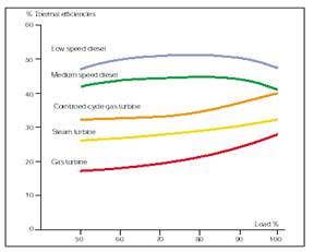
Fig. 7.5: Typical part load efficiencies of prime movers [7.2]
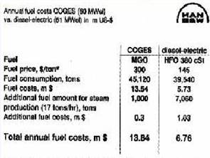
Fig. 7.6: Annual fuel costs of COGES versus diesel-electric system [7.1]
The specific fuel consumption rates (SFOC) in g/kWh over the total electrical plant output for the various propulsion concepts are plotted in Fig. 7.5. From 90% power down to approx. 60% power, the thermal efficiency is almost constant. Contrary to this favorably flat fuel consumption line, the turbines' consumption rates are highly load-dependent. At very high rate power, COGES has a thermal efficiency of around 40%, a value that is only slightly higher than that of diesel engines' figure indeed. However, this high electrical power is hardly used in cruising: most of the time, the turbines have to operate at part load with much higher specific fuel consumption rates.
Calculation of the annual fuel costs was based on the following typical weekly load scenario:
60 hours per week in ports (power requirement 10 MW):
One 12V 48/60 Diesel engine or one gas turbine with the steam turbine in operation This sums up to 3 840 operating hours per year for each of the five diesel engines, and 6 150 hours for each of the two gas turbines. For this load profile and for average August 2000 fuel prices for North West Europe, the total fuel costs are shown in Fig. 7. The difference in annual fuel costs between COGES and the diesel-electric option is US-$ 7 million.
The total sum of fuel costs (Fig. 7.6) and lube oil costs is US-$ 13.86 million for COGES and US-$ 7.04 m for the diesel-electric system. The difference is US-$ 6.8 million per year. With the total annual net profit of only US-$ 2.1 million, it is impossible to compensate higher fuel bill of COGES. With bunker prices in September 2000, there is a loss of US-$ 4.7 million every year and for every ship and this does not include the higher first and maintenance costs.
In comparison to a COGES system, diesel-electric solutions have clear advantages in many aspects, with the exception of weight and size, and NOx emission and noise. These advantages are of uniform machinery, lower fuel costs and lower fuel consumptions and therefore lower CO2 emission, lower first costs, operating costs, easier maintenance, lower maintenance costs and wider operational flexibility and redundancy on account of the larger number of diesel engines that are able to burn widely varying fuel qualities. The gas turbine itself, as an intrinsically simple rotating machine, is highly reliable and durable as it has fewer moving parts and lower friction losses, but the more complicated COGES system involving a steam turbine genset had no chance up to now to prove its availability and long-term reliability in cruise shipping.
7.2 High-Speed Diesel Engines
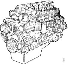
7.2.1 Introduction to SCANIA 12-Liter Engine
The following description is referred from the user’s manual of SCANIA 12-liter diesel engine.
7.3 Medium-Speed Diesel Engines
7.3.1 Introduction to Wärtsilä L46 Diesel Engine
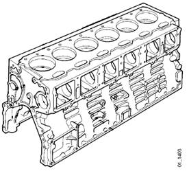
The Wärtsilä 46 (Fig. 7.3.1) is a medium-speed engine for which reliability and total Economy have been the guiding principles. Extensive testing in Wärtsilä modern diesel laboratory by several thousand running hours has made the Wärtsilä 46 a really reliable diesel engine. Laboratory testing is full-scale engine testing: it covers various types of endurance testing, and also combustion measurements and system optimizations. All these confirm theoretical calculations, simulations as well as performance mapping of such factors as heat balance, fuel and lube oil consumption, exhaust emission, noise and vibration level.
Fig. 7.29 General view of Wärtsilä 46 engine
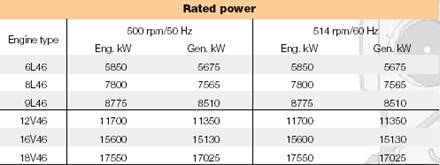
The following is a summary of Wärtsilä NSD’s approach to design and technology in the Wärtsilä 46 engine [7.3]. The main technical data and rated power are listed in Table 7.3.1 and 7.3.2, respectively.
Table 7.3.1: Main technical data of Wärtsilä 46 marine engine
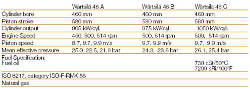
Table 7.3.2: Rated power data of Wärtsilä 46 marine engine
7.3.1.1 Low NOx Combustion and Direct Water Injection
Any hydrocarbon can be burnt provided the temperature is right and there is sufficient oxygen. However, the way it is burnt has a great effect on thermal efficiency and exhaust emissions, particularly NOx formation. Wärtsilä NSD has developed a low NOx combustion process that reduces the NOx level up to 50% without compromising on thermal efficiency. The low NOx combustion technology is based on the following:
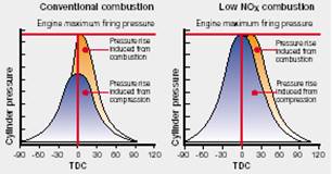
Fig. 7.30: Conventional combustion versus Wärtsilä 46 low NOx combustion
The engine with direct water injection is equipped with a combined injection valve and nozzle that allows injection of water and fuel oil into the cylinder. This means that neither of the modes (water on/off) will affect the operation of the engine. Water is fed to the cylinder head at high pressure, 210 bar. High water pressure is generated in a high-pressure water pump module. The pumps and filters are built into modules to enable easy, and require a minimum of space. A flow fuse is installed on the cylinder head side. The flow fuse acts as a safety device, shutting off the water flow into the cylinder if the water needle gets stuck. Water injection timing and duration is electronically controlled by the control unit, which gets its input from the engine output. NOx reduction of 50-60% can be reached without adversely affecting power output.
7.3.1.2 Major Improvement in Engine Components
(1) Injection pump
As shown in Fig. 7.31, the mono-element design is a rigid and distortion-free solution even at high injection pressures. A constant pressure relief valve eliminates the risk of cavitation erosion by maintaining a residual pressure, which is on a safe level over the whole operating field. A drained and sealed-off compartment between the pump and the tappet prevents leakage fuel from mixing with lubricating oil. Precalibrated pumps are interchangeable.
(2) Injection valve
The valve (Fig. 7.32) is designed to have a small heat absorbing surface facing the combustion space together with efficient heat transfer to the cooling water. This eliminates the need for a separate nozzle temperature control system. The fuel is transported the shortest way from the pump to the valve, i.e. via a high-pressure pipe in the cylinder head.
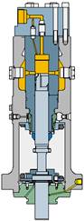
Fig.7.3.3: Fuel pump
Fig. 7.32 Injector valve
(3) Turbocharging system
Wärtsilä 46 is provided with Spex (Single pipe exhaust) system and with high efficiency turbocharger (Fig. 7.33). The Spex turbocharging system is an exhaust gas system that combines the advantages of both pulse and constant pressure charging. Compared with a constant pressure system, the ejector effect of the gas pulses will provide better turbine efficiency at partial loads. The Spex system is practically free from interference. This means very small deviations in the scavenging between the cylinders and consequently an even exhaust gas temperature. The modular-built exhaust gas systems are durable enough to handle high-pressure ratios and pulse levels, but at the same time elastic enough to cope with thermal expansion in the system. The turbocharger has the highest available efficiency (Fig. 7.34). The turbocharger is equipped with plain bearings and there is no cooling water. The turbocharger is fitted with cleaning devices for both the compressor and the turbine side. Exhaust waste-gate and air by-pass are used to obtain specific requirements on the operating range, load response or partial load.
Fig. 7.33: Wärtsilä 46 Spex (Single pipe exhaust) system
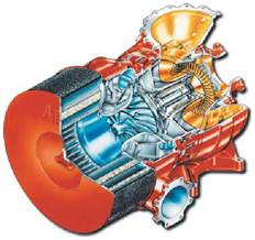
Fig. 7.33: Wärtsilä 46 turbocharger
(4) Piston and piston ring set
A composite low-friction piston with a nodular cast iron skirt and a steel top as shown in Fig. 7.34. The special cooling gallery design assures efficient cooling and high rigidity for the piston top. The design can handle combustion pressures beyond 200 bar. Hardened top ring grooves assure a long lifetime. Low friction is ensured by the skirt lubrication system. A well distributed clean oil film that eliminates the risk of piston ring scuffing and reduces the wear rate. Cleaner rings and grooves free from corrosive combustion products. Hydraulically damped tilting movements provided by an oil pad between the liner and the piston, resulting in less noise and wear.
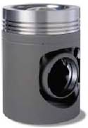
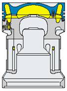
Fig. 7.34: General view of Wärtsilä 46 piston

Fig. 7.35: General view of Wärtsilä 46 piston ring sets
Piston ring set (Fig. 7.35) is proven of low friction that has special wear resistant coating for the compression rings and dimensioned and profiled for maximum sealing and pressure balance.
(5) Connecting Rod
The connecting rod (Fig. 7.36) is a three-piece marine design, where combustion forces are distributed over a maximum bearing area and where the relative movements between mating surfaces are minimized. Piston overhauling is possible without touching the big end bearing and the bearing can be inspected without removing the piston. The three-piece design also reduces the piston overhauling height. All nuts are tightened with hydraulic tool.
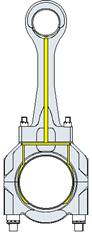
Fig. 7.36: Cross-sectional view of Wärtsilä 46 connecting rod
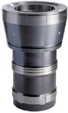
Fig. 7.37: General view of Wärtsilä 46 cylinder liner
(6) Cylinder Liner and Anti-polishing Ring
Cylinder liner (Fig. 7.37) deformations are normally caused by cylinder head clamping, thermal and mechanical load. A special design with a high collar-to-stroke ratio, the deformations in this liner are very small. A round liner bore in combination with excellent lubrication improves conditions for the piston rings and reduces wear. To eliminate the risk of bore polishing, the liner is provided with an anti-polishing ring in the upper part. The purpose of this ring is to “calibrate” the carbon deposits on the piston top land to a thickness small enough to prevent contact between the liner inner wall and the deposits on the piston top land. “Bore-polishing” can lead to local liner wear and increased lube oil consumption. The temperature distribution in the cylinder liner is important not only in terms of stress and deformation but also decisive for the cylinder liner wear rate. The temperature must remain above the sulfuric acid dew point to avoid corrosion, but at the same time remain sufficiently low to avoid lubricating oil breakdown. The material composition is based on long experience with the special gray cast iron alloy developed for excellent wear resistance and high strength.
(7) Crankshaft and bearings
The crankshaft design allows for use of high combustion pressure and still maintains a conservative bearing load. As shown in Fig. 7.38, the crankshaft is forged in one piece, fully machined and rigid due to moderate bore/stroke ratio and large pin and journal diameters. The crankshaft also fitted with counterweights on every crank web. It is designed for full power take-off, also from the free end.
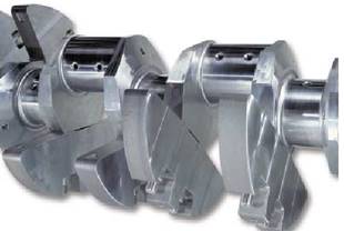
Fig. 7.38: General view of Wärtsilä 46 crankshaft
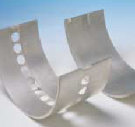
Fig. 7.39: General view of Wärtsilä 46 bearing pad
The thick-pad bearing (Fig. 7.39) design emphasizes one key concept of reliability. The bearing loads have been reduced by increasing crankshaft journal and pin diameters as well as length. Low bearing loads allow for softer bearing materials with greater conformability and adaptability. This makes the bearing virtually seizure-free.
(8)Cooling and lubrication oil systems
The fresh water cooling system (Fig. 7.40) is divided into high temperature and low temperature cooling system. The high temperature cooling water system operates constantly at a high temperature level to make the temperature fluctuations in the cylinder components as small as possible and preventing from corrosion due to undercooling. For obtaining maximum heat recovery the charge air cooler is split into a high and low temperature section.
Engine driven pumps can be provided as an option for marine application. In power plant application, these are standard.
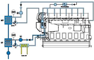
Fig. 7.40: Schematic of Wärtsilä 46 cooling system
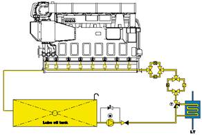
Fig. 7.41: Schematic of Wärtsilä 46 lubrication oil system
Marine engines have dry sump and power plant engines wet sump. The lube oil is treated outside the engine by continuous separating. On the way to the engine, the oil passes through a lube oil cooler, a full flow automatic filter unit and a safety filter for final protection. For the purpose of running-in, provision has been made for mounting special running-in filters in the crankcase in front of each main bearing. Engine driven lube oil pump can be provided as an option for marine application. In power plant application this is standard.
7.1 Prospects in Medium-Speed Diesel Engines
7.1.1 Merits of Diesel Engines and Gas Turbine in Marine Propulsion
7.1.1.1 Weight and size
7.1.1.2 First and maintenance costs
7.1.1.3 Fuel and operating costs
7.1.1.4 Vibration, noise and lube oil consumption
7.1.1.5 Efficiency
7.2 High-Speed Diesel Engines
7.2.1 Introduction to SCANIA 12-Liter Engine
7.3 Medium-Speed Diesel Engines
7.3.1 Introduction to Wärtsilä 46 Diesel Engine
Reference:
[7.1] Koehler, H. W., 2000, “Diesel Engines and Gas Turbines in Cruise Vessel Propulsion”, The Institution of Diesel and Gas Turbine Engineers, London.
[7.2] MAN B&W, 2001, “Very Large Diesel Engines for Independent Power Producers and Captive Power Plants”, Denmark.
[7.3] Wärtsilä NSD, 2001, “Wärtsilä 46 Technology Review”, Finland.
Source: http://research.nkmu.edu.tw/%E5%90%84%E9%A0%85%E6%88%90%E6%9E%9C%E5%B1%95/%E5%
8D%93%E8%B6%8A%E8%88%AA%E8%BC%AA%E6%95%99%E8%82%B2%E8%A8%93%E7%B7%B4%E4%B8%AD%E5%BF%83/08-diesel_eng.doc
Web site to visit: http://research.nkmu.edu.tw
Author of the text: indicated on the source document of the above text
If you are the author of the text above and you not agree to share your knowledge for teaching, research, scholarship (for fair use as indicated in the United States copyrigh low) please send us an e-mail and we will remove your text quickly. Fair use is a limitation and exception to the exclusive right granted by copyright law to the author of a creative work. In United States copyright law, fair use is a doctrine that permits limited use of copyrighted material without acquiring permission from the rights holders. Examples of fair use include commentary, search engines, criticism, news reporting, research, teaching, library archiving and scholarship. It provides for the legal, unlicensed citation or incorporation of copyrighted material in another author's work under a four-factor balancing test. (source: http://en.wikipedia.org/wiki/Fair_use)
The information of medicine and health contained in the site are of a general nature and purpose which is purely informative and for this reason may not replace in any case, the council of a doctor or a qualified entity legally to the profession.
The texts are the property of their respective authors and we thank them for giving us the opportunity to share for free to students, teachers and users of the Web their texts will used only for illustrative educational and scientific purposes only.
All the information in our site are given for nonprofit educational purposes