Module 3: Web bonding processes
3.1 Mechanical Bonding Processes
Needlepunching process
Principle
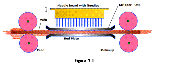 Needlepunching is a nonwoven process by which the fibres are mechanically entangled to produce a nonwoven fabric by repeated penetration of barbed needles through a preformed dry fibrous web. The machine which accomplishes this process is known as needle loom. Figure 3.1 displays the schematic diagram of a needle loom. The fibrous web, which is unbonded and therefore thick and voluminous, is fed to the machine by a pair of feed rollers. It then goes to the working zone of the machine and passes in-between a pair of perforated bed plates. The needles are arranged in a needle board in width-wise rows. The needle board is mounted on a beam which is given an up and down reciprocating motion by means of an eccentric crank mechanism. In the down stroke mode, the needles descend through the perforations of the top bed plate, through the web, and through the perforations of the bottom bed plate. During the upstroke, the barbed needles withdraw upwards and the bed plate strips the web off the needles. As a result, the fibres are mechanically interlocked, thereby providing the mechanical strength. The needle bonded nonwoven is delivered by a pair of delivery rollers.
Needle
Needles are the heart of the needlepunching process. The schematic diagram of a typical needle is shown in Figure 3.2. As shown, a needle has the following parts: crank, shank, taper, blade, barb, and point. The shank locates in the hole in the needleboard and the crank is clamped between upper surface of the needleboard and the needlebeam, thus holding it firmly and vertically aligned in the loom. Traditionally, the cross-section of a needle is triangular and carries a total of nine barbs, three per apex. The dimensions of the barbs and their relative arrangement vary depending on the application and machine operation.
In general, the nonwoven industry uses two types of needles, known as single reduction needle and double reduction needle. They are shown in Figure 3.3. The single reduction needle has two sections, shank and blade. But the double reduction needle has an intermediate section in-between the shank and the blade. This is a transition stage between the different diameters of the shank and the blade. The single reduction needle is much stiffer than the double reduction needle. The single reduction needle is usually made only for coarser gauge needles. The single reduction needle is used for stiff fibres (waste fibres, shoddy, etc.)
The barb is known to be the main working component of a needle. The schematic diagram of a barb along with its important parts is shown in Figure 3.4. A barb is characterized primarily by kick-up, spacing, angle, and depth. As far as the kick-up is concerned, there exist high kick-up (‘K’ barb), low kick-up (‘NK’ barb), and no kick-up (‘B’ barb). These barbs are shown in Figure 3.5. The fibre carrying capacity decreases from ‘K’ barb to ‘NK’ barb to ‘B’ barb. Based on the spacing, the barbs are categorized by regular barb (RB), medium barb (MB), close barb (CB), and high density barb (HDB). These barbs are shown in Figure 5.6. The high density barb provides maximum aggressive punching, followed by the close barb, medium barb, and regular barb. At the same time, the surface of the fabric is found to be maximum uneven with the high density barb, followed by the close barb, medium barb, and regular barb. There exist barbs with different angles, as shown in Figure 3.6. It is generally known that the higher is the angle the higher is the fibre carrying capacity of the barb. The depth of the barb is also an important parameter for the selection of a barb. Actually, the depth of a barb relative to fibre diameter is a very important characteristic as it decides the capacity of a needle to collect and transfer fibres into the vertical plane. If nf is the number of fibres collected in the barbs of a needle, bd is the depth of a barb, df is the fibre diameter, and nb is the number of barbs of a needle, then
.
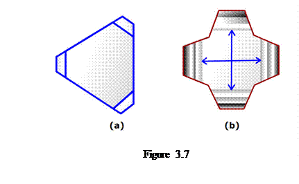
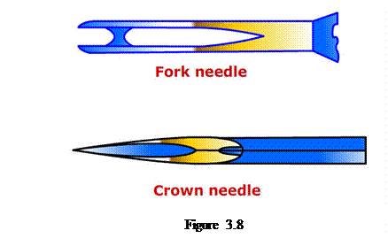 In nonwoven industry, a wide variety of needles are used. They vary in their cross-sectional shape as well as the geometry of the point of the needle. The blade cross-section of classical needles is triangular, with three barbs formed on the apex. This is shown in Figure 3.7(a). The star bladed needles have four apices and a cruciform cross-section. This needle is intended to carry an increased number of fibres per penetration as compared to the standard triangular needle, which can increase fabric strength. This is shown in Figure 3.7(b). Besides there are fork needles used for structuring and patterning pre-needled fabrics. The crown needles are designed to be used in conjunction with random velour needleloom to introduce fibre loops that protrude from the surface of the fabric. These needles are shown in Figure 3.8
Selection of needle
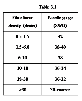
 The selection of needle is very important for getting good quality nonwoven fabrics. It is decided by many factors, discussed earlier, along with the fineness of the fibres required to be processed. Table 3.1 lists the gauge of the needles for different finenesses of fibres. The higher is the gauge of the needle, the finer is the needle and vice-versa.
Arrangement of needle boards
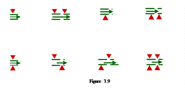
The modern machine manufacturers offer various arrangements of needle boards in needle looms. Figure 3.9 displays the different arrangements of needle boards. Typical applications of these arrangements are filtration media, synthetic leather, floor coverings, underlay, automotive headliners, and blankets, etc.
Critical process parameter
The quality of the needle bonded nonwoven fabric is decided not only by the design of the needles, but also by the punch density of the needles. Punch density is defined by the number of needle penetrations per unit area of the resulting fabric. If ξ is punch density, n is the number of needles per unit width of needleboard, A is the fibre web advance per stroke, P is the rate of production, and m is the number of punches per unit time, then
 .
.
Therefore, when the needle board density is constant and for a given stroke frequency, the punch density is determined by adjusting the fabric throughput rate. To obtain higher punch density of a finished fabric it usually requires two or more needlelooms. Depending on the scale of production, these passages may take place as separate operations or may form a continuous production line.
Applications
Today the needle-bonded nonwovens are finding a wide variety of applications, including geosynthetics, filter media, synthetic leather, waddings and paddings, floor coverings, automotive fabrics, insulation, blankets, wipes, roofing, etc.
Principle
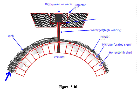
Hydroentanglement, spunlacing, hydraulic entanglement, and water jet needling are synonymous terms describing the process of mechanically bonding the fibres in a web by means of high energy water jets. The machine which accomplishes this is known as hydroentanglement or spunlace machine. The basic elements of this machine are shown in Figure 3.10. A series of multiple high pressure columnar water jets is produced by pumping water through a series of fine nozzles in a jet strip clamped into an injector (manifold). The high velocity water jets are directed to the unbonded web, which is supported on a moving perforated conveyor. The conveyor may have a flat bed surface or cylindrical surface. The entanglement among the fibres is introduced by the combined effects of the incident water jets and the turbulent water created in the web which intertwines neighbouring fibres. The conveyor sleeve being permeable enables most of the de-energised water to be drawn into the vacuum box for recycling and reuse.
 Selection of fibres
Both natural fibres and synthetic fibres are used in hydroentanglement process. The wood pulp is often blended with staple fibres and used in hydroentanglement process. Viscose fibre has been found to be mostly used. The important fibre properties for this process have been fibre flexural rigidity and fibre hydrophilicity. Viscose rayon has a low wet modulus and this partly explains the ease with which this fibre can be hydroentangled as compared to polypropylene fibres that have higher modulus. As the coarser fibres offer higher flexural rigidity as compared to the finer fibres, the former require more hydroentagling energy as compared to the latter in order to have the same degree of bonding. Effective hydroentanglement requires uniform and rapid wetting of the web. That is why the manmade fibres are often treated with hydrophilic finishes before hydroentanglement.
Critical process factors
The critical process factors of the hydroentanglement process are specific energy and jet impact force.
Specific energy is defined as the energy expended per unit time for unit mass of fabric processed per unit time. As the hydroenglement process deals with transfer of kinetic energy from the water jets to the web, the specific energy is very important in deciding the degree of bonding of fibres. It is possible to derive the following expression of specific energy

where η is specific energy, Cd is nozzle discharge coefficient, ρ is density of water, w is basis weight of fabric, b is width of fabric, v is velocity of conveyor belt, ni is no. of jets in i-th injector per unit length of i-th injector (manifold), li is length of i-th injector, di is diameter of water jet nozzle in i-th injector, Pi is pressure of water jet at i-th injector, and M is no. of injector. Often, the specific energy coefficient, which is defined by the ratio of energy consumption to the fabric tensile strength, is calculated as a useful means of assessing the efficiency of hydroentanglement in terms of the development of fabric strength. This is expressed as follows

where ![]() is the ratio of average of tensile strength in the machine direction and the cross-direction to the basis weight of the fabric.
is the ratio of average of tensile strength in the machine direction and the cross-direction to the basis weight of the fabric.
Jet impact force affects the consolidation, thickness, and entanglement of the web during hydroentanglement and depends on the water pressure and jet impact area which is influenced by the jet diameter. This is shown below.
![]()
where Fi is force imparted by a nozzle in i-th injector, di is diameter of water jet nozzle in i-th injector, and Pi is pressure of water jet at i-th injector. Therefore, at a fixed pressure, the impact force will increase if the nozzle diameter increases providing a potentially more effective means of increasing fibre entanglement by involving more fibres in the working field of entanglement.
Nozzle
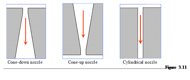
The nozzles used in hydroentanglement process are capillary cone nozzles, where the nozzles are usually operated in the cone-down rather than the cone-up position. This type of nozzles is known as cone-down nozzle. Besides the cone-down nozzle there are cone-up and cylindrical nozzles available. Figure 3.11 shows the geometry of these three nozzles. It is of interest to know the discharge coefficient of the nozzles and the resulting break-up length of the jets. Discharge coefficient is defined by the ratio of the actual mass flow rate to the ideal mass flow rate of water. Break-up length is defined by the length of jet at which it breaks after exiting from the nozzle. The higher is the break-up length, the higher is the energy transmitted to the web. The cone-up nozzle has a remarkably higher discharge coefficient than the cone-down and cylindrical nozzles. This can be explained by the natural consequence of the geometry of the nozzles. The images of the jets after exiting from the three different nozzles for different pressures are displayed in Figure 3.12 [1].
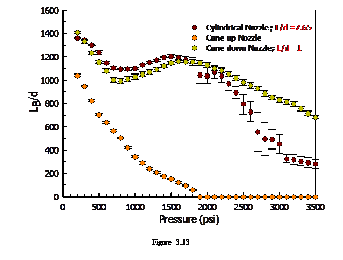
. The break-up length profile of these nozzles is displayed in Figure 3.13. It can se seen that the break-up length of the cone-down nozzle is the lowest among the three nozzles. At lower pressure, the break-up length of the cone-down and cylindrical nozzles is practically the same, but at higher pressure the cone-down nozzle shows higher break-up length than the cylindrical nozzle. This can be explained by the constricted water jet issued from the cone-down nozzle, while the water jet issued from the cone-up nozzle is non-constricted. In constricted jet, water is in contact with the ambient air and not the orifice wall, but in non-constricted jet, water is in contact with the orifice wall.
 Web support system
The webs in the working field of the hydroentanglement machine are supported by forming wires whose surface topography has a direct influence on the appearance of final product.
Jet streak
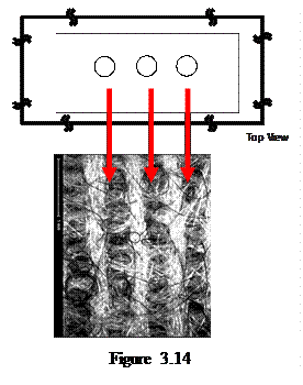
One of the major problems associated with the quality of the hydroentangled nonwoven is related to the jet marks or jet strip. This is undesirable as it spoils the aesthetic appearance of the fabric and reduces the mechanical properties of the fabric. This is shown in Figure 3.14. This effect can be reduced by having the staggered arrangement of the nozzles having one row with higher nozzle diameter and other row with lower nozzle diameter.
Applications
 The hydroentangled nonwovens are used in a wide variety of applications, including wipes, surgical fabrics, medical gauge, filter cloths, artificial leather, automotive fabrics, linings and clothes, etc.
3.2 Thermal Bonding Processes
Introduction
It is known that the fibres in the webs can be bonded thermally in order to have sufficient resistance to mechanical deformation. The basic concept of thermal bonding was introduced by Reed in 1942. He described a process in which a web consisting of thermoplastic and non-thermoplastic fibres was made and then heated to the melting or softening temperature of the constituent thermoplastic fibres followed by cooling or solidify the bonding area. Since then many developments have been made in thermal bonding processes. Today the thermal bonding processes include calender bonding, through-air bonding, infrared bonding, and ultrasonic bonding. Thermal bonding requires a thermoplastic component to be present in the web in the form of homofil fibre, powder, film, hot melt or as a part (sheath) of bicomponent fibre. The thermoplastic component becomes viscous under the application of thermal energy. The polymer flows to fibre-to-fibre crossover points where bonding regions are formed. The bonding regions are fixed by subsequent cooling. The thermal bonding process is environmental-friendly, as no latex binder is required. The thermal bonding process consumes less energy compared to foam bonding or hydroentanglement bonding.
Principle of thermal bonding
The formation of a bond during thermal bonding follows in sequence through three critical steps:
The time scales for these processes closely match commercial practice.
The formation of a bond requires partial melting of the crystals to permit chain relaxation and diffusion. If, during bonding, the temperatures are too low or if the roll speeds are too high, the polymer in the mid-plane of the web does not reach a high enough temperature to release a sufficient number of chains or long enough chain segments from the crystalline regions. Thus, there will be very few chains spanning the fibre-fibre interface, the bond itself will be weak, and the bonds can be easily pulled out or ruptured under load, as observed. Under-bonding occurs when there are an insufficient number of chain ends in the molten state at the interface between the two crossing fibres or there is insufficient time for them to diffuse across the interface to entangle with chains in the other fibre. Over-bonding occurs when melting occurs and many chains have diffused across the interface and a solid, strong bond has been formed. If the web reaches a sufficient temperature, many chains or chain segments are released from the crystal, repeat across the fibre-fibre interface, and form a strong bond. The fibres within the bond spot have lost their orientation and their strength. At the same time, the polymer chains within the fibres located in the vicinity of the bond also lose some of their molecular orientation (and strength) at the fibre-bond interface.
 In well-bonded webs, failure occurs at the bond periphery because the bridging fibres are weak in the region adjacent to the bond, but strong elsewhere. If the bridging fibres have the same strength over their entire length, including the region at the bond periphery, better load sharing would lead to a stronger web.
Raw materials
The thermal bonding processes utilize either thermoplastic fibres alone or blends containing fibres that are not intended to soften or flow on heating. The non-binder fibre components may be referred to as the base fibres or sometimes, carrier fibres. Commercially, a variety of base fibres are used. The binder fibre component normally ranges from 5-50 % on weight of the fibre depending on the targeted properties of the final product made thereupon.
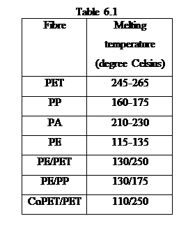
The base fibres can be of natural or synthetic or mineral or metallic origin. The binder fibres can be momocomoponent (homofil) like polyester (PET), polypropylene (PP), polyamide (PA), and polyethylene (PE) and bicomponent (sheath-core) like PE/PET, PE/PP, and CoPET/PET. Looking at the thermal bonding process, it is important to note down the melting temperature of these fibres.
Calender bonding process
Process description
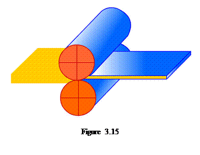 In thermal calender bonding process, the fibrous web containing thermoplastic fibres is passed through a heated calender nip that is created by two rolls (cylinders) pressed against each other (Figure 3.15). One or both rolls are heated internally to a temperature that usually exceeds the melting point temperature of the binder fibres to ensure there is sufficient hear transfer to induce softening at the prevailing line speed. As the web passes between the calender nip, fibres are heated and compressed. This causes the binder fibres to become soft and tacky and induces polymer flow in and around the base fibres. The fluid polymer tends to collect at the fibre crossover or contact points and bonding sites are formed. Cooling leads to solidification of the polymer and bonding.
Principle
The dominant mode of heat transfer in this case is conduction. Dharmadhikary et al. [2] reported the principle of calendar bonding process as follows. The one-dimensional heat equation can be written as
![]()
In dimensionless form, this can be written as
![]()
where ![]() .
.
Here, T1 is calender roll surface temperature, T is web temperature, T0 is ambient temperature, y is the distance from center of web measured in thickness direction, b is half web thickness, and α is thermal diffusivity. The initial condition can be stated as ![]() and the boundary condition can be mentioned as
and the boundary condition can be mentioned as ![]() . The solution of this problem is
. The solution of this problem is  . It is graphically shown in Figure 3.16.
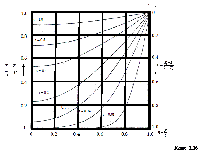
It can be seen that the convergence of the series depends on dimensionless time and there is a significant temperature that exists in-between center and surface of the web.
Types of calender roller
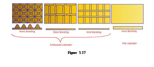 There exist two types of calender rollers, that is, embossed calender and flat calender. These calender rollers are shown in Figure 3.17. It is generally known that the point bonding results in softer fabric and the area bonding results in stiffer fabric.
Heating arrangement
The roll surfaces are heated from inside by direct electrical heat or through the use of heated oil. Heated oil is preferred because it leads to more uniform temperature distribution along the nip. In some configurations a fixed quantity of oil is sealed inside the roll and it is heated electrically. Thermal inertia of internally heated systems with or without oil is generally high. As a result heating by circulating oil systems is much preferred. The calender roll systems must be so designed as to provide very uniform temperature and nip pressure profiles all along the nip length. This is an engineering challenge of major proportions. As a result the technology of making rolls for calender bonding is quite complex.
Critical process parameters
The critical process parameters of thermal calender bonding process are roller temperature, roller nip pressure, and contact time.
Roller temperature should be adjusted in such a way that the “sintering” of fibre surfaces can be achieved while avoiding complete fibre melting and film formation. Increasing bonding temperature up to a certain point increases the tensile properties of the fabric due to the formation of well-developed bonding structure. Further increase in temperature reduces the tensile properties which may be attributed to the loss of fibre integrity and the formation of film like spot as well as the reduction in load transfer from fibre to bonding point. Over-bonding of this kind leads to “popping” of the structure under tensile load as the fabric fails at the bond locations.
The nip pressure influences the transfer of heat from the rollers to the web (The so-called “pressure-induced heating”.) If F is force exerted onto the roller,δ0 is initial thickness of the web, δ1 is final thickness of the web, V is volume of web to melt, W is basis weight of the web, A is area of the web, ρ is density of fiber, Cp is heat capacity, ∆T is temperature rise, ∆Hm is heat of fusion, χ is crystallinity, and f is fraction of crystal that melts, then it can be written that
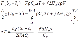
Polymer molecules subjected to compression require more thermal energy to melt compared to when they are at atmospheric pressure. This indicates that, as the pressure is raised, the melting temperature will increase. This is known as Clapeyron effect. Mathematically,
![]()
where P is pressure, T is temperature, ∆H is molar enthalpy of melting, and ∆V is molar volume change on melting. The slope is positive. The increase in melting point temperature of polypropylene fibres is found to be 38 K/kbar.
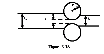 The time of contact between roller and web is also important for the quality of the fabric. The time of contact depends on the nip width and the velocity of the rollers. Figure 3.18 shows the initial web thickness is δ0, final fabric thickness is δ1, nip distance is δ2, and roll radius is r. It is then possible to derive the following expression for time of contact
![]()
where t is contact time, h is nip width, and v is roller velocity. In general, the contact time for light weight fabrics is kept to be 0.001 s, but for medium weight fabric, it is kept at 0.1-0.7 s.
Through-air bonding process
Introduction
The demerit of the calendar bonding process lies in the fact that it results in reduction of thickness of the fabric. In some applications, for example, thermal insulation, acoustical insulation, etc., where the thickness of the fabric dictates the performance of the nonwoven products, the thermal calendar bonding process is not desirable. The solution to this problem is through-air bonding process. The through-air bonding process is generally applicable for high bulk and heavy weight nonwovens. This bonding process primarily relies on convection mechanism of heat transfer.
Process description
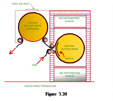
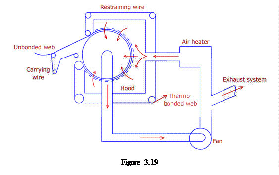 Figure 3.19 displays the schematic diagram of the through-air bonding machine. The main component of this system is an air permeable drum with a high open area onto which the web is transferred and supported by a travelling/carrying wire. The perforated drum is covered with a hood from where the heat is delivered; the hot air is drawn through the web cross-section by means of a suction fan.
Types of through-air bonding machine
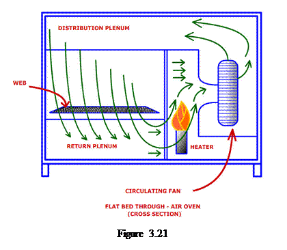 Generally three types of through-air bonding machines are used. They are perforated drum though air bonding machine, perforated conveyor (flat bed) through air bonding machine, and impingement (air jetting) through air bonding machine.
Figure 3.20 shows the schematic diagram of a perforated drum though air bonding machine. Here the web is carried by a permeable screen around a perforated drum enclosed in a chamber. The upper part of the chamber serves as a plenum into which heated air is blown in. Inside the drum, there are baffles covering the circumference except the portion through which heated air can be sucked in through the fabric. The air suction is aided by suction boxes located inside the drum. The sucked-in air is then re-heated and circulated back to the heating zone. This system is suitable for light weight webs of 10 g/m2 to heavy but permeable webs up to 3000 g/m2.
Figure 3.21 shows the schematic diagram of a perforated conveyor though air bonding machine. Here the web to be bonded moves on a permeable support screen over a flat bed. Above the flat bed is a plenum into which heated air is blown in. Below the flat bed are vacuum units which suck the heated air from the plenum above, through the passing fabric over the flat bed. The air is circulated back into the heating zone after re-heating. This system is particularly suitable for bulky, low-density webs.
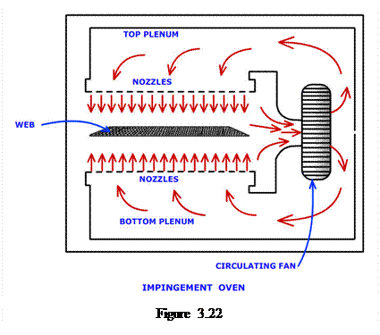 Figure 3.22 shows the schematic diagram of an impingement through-air bonding machine. In impingement bonding, the web is carried over a permeable screen into an oven. In the oven are a series of boxes (plenums) positioned across the web passage. Hot air is pumped into the boxes from one end, the other being closed. The lower surface of the box contains an evenly spaced series of nozzles through which jets of hot air impinge on the surface of the web passing beneath. While some hot air may diffuse through the web most of it is deflected in different directions on the surface. Maximum bonding occurs at the surface and decreases as one goes into the thickness. In the case of denser webs, or to obtain symmetry of bonding in the web, boxes containing nozzles may be placed below the web carrying screen. In these cases, the nozzles are aimed upward so that hot air jets. This is mainly used for denser webs or webs that must be bonded gently.
 Infrared bonding process
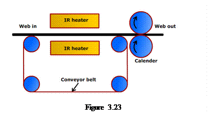
Figure 3.23 shows the schematic diagram of an infrared bonding machine. The mechanism is thermal radiation. The IR emitting bulbs (heaters) are used to radiate electromagnetic energy in part of the IR wave length (0.7-300 μm) which then translates to heat by the receiving /absorbing material. The heat flux emitted by a heater is E=εσT4, where E…heat flux (W/m2), σ is Boltzmann constant (5.67![]() 10-8 W/m2), ε is emissivity (0 to 1) and T is absolute temperature (K). It does not require any medium, but does not penetrate deep into a structure. For thinner webs, it is not economical. This is mainly used for glazing the surface of thick nonwovens.
10-8 W/m2), ε is emissivity (0 to 1) and T is absolute temperature (K). It does not require any medium, but does not penetrate deep into a structure. For thinner webs, it is not economical. This is mainly used for glazing the surface of thick nonwovens.
 Ultrasonic bonding process
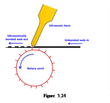
Figure 3.24 shows the schematic diagram of an ultrasonic bonding machine. Here the web is compacted between an embossed patterned roller (anvil) and an ultrasonic horn. The horn is vibrated at a frequency of 20-40 KHz. The friction between horn and web surface heats fibers above the raised points on the anvil. Mechanical energy is converted into thermal energy. This is mostly used for joining nonwoven laminates.
3.3 Chemical Bonding Processes
Introduction
In chemical bonding, chemical binders (adhesive materials) are used to hold the fibers together in a nonwoven fabric. Chemical binders are polymers that are formed by emulsion polymerization. The mostly used binders today are water-borne latexes. They are applied in a number of different ways to nonwovens and because of their viscosity is close to that of water they can easily penetrate into nonwoven structure by emulsion. After application of binder by, for example, immersion, they are dried and the water evaporates. The binder then forms an adhesive film across or between fibre intersections and fibre bonding takes place.
Chemical binders
There are various chemical binder polymers used including vinyl polymers and copolymers, acrylic ester polymers and copolymers, rubber and synthetic rubber, and natural binders, principally starch. These are usually applied in aqueous dispersions but can be supplied as polymer solutions providing they have sufficiently low viscosity to allow penetration into the web.
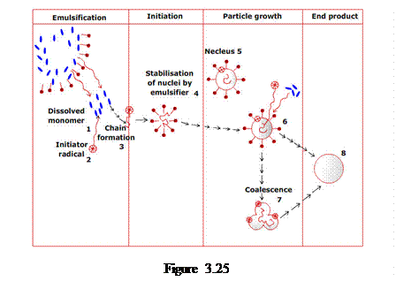 Commercially, latex polymers are the most commonly encountered binder because of their availability, variety, versatility, ease of application, and cost-effectiveness. The latex polymers are prepared by emulsion polymerization by controlled addition of several components. These components include monomers (building block), water (medium), initiator (decomposes to form free radicals to start the polymerization process), surfactant (to prevent particle attraction and thus stabilize the emulsion particles) and chain transfer agent (to control the final polymer molecular weight). The process of latex formation starts with a distribution of monomer droplets in water, stabilized by emulsifiers that have accumulated at the interface to the water phase. The emulsifier molecules have the hydrophilic heads and hydrophobic tails. In Figure 3.25, the dot indicates the hydrophilic head and the line represents the hydrophobic tail of emulsifier molecule. If the concentration of the emulsifier is above a critical value, a spheroidal collection of them is formed. This is called micelle and it typically contains about a hundred emulsifier molecules. The initiator added is decomposed to form water-soluble free radicals. When a free radical encounters monomer molecules dissolved in water, it reacts successively with several to form a short polymer chain. This short chain, called oligomer radical, is no longer soluble in water. It precipitates and is stabilized by the emulsifier, which accumulates at the newly formed interface. This is now called a latex particle. When there are enough oligomer radicals formed they grow into latex particles. Also, it is possible for a growing oligomer radical to meet a monomer droplet and initiate polymerization to form a latex particle. In this case, the latex particle would be large. In addition, when the oligomer radical meets an emulsifier micelle where monomer molecules are diffused in, the monomers polymerize and form another latex particle. This can occur only if the concentration of emulsifier is enough high, that is, above the critical micelle concentration. Once the formation of latex particles is completed, their growth starts. The monomers flow from water to the latex particles where the polymerization occurs. The latex particle grows larger and contains hundreds or thousands of closely packed molecules in one particle. As propagation proceeds more latex particles are added in layers to form a larger latex particle. Sometimes it is desirable to limit the molecular weight of the polymer by introducing a chain transfer agent. The growing polymer radical combines with the chain transfer agent to stop the chain growth.
Methods of binder application
The most common methods of applying a binder to a dry-laid web are saturation, foam, spray, and print bonding methods. For wet-laid nonwovens, most of the same methods can be used but bonding must be applied after partial drying. For printing, the web must be dry.
Saturation bonding process
Saturation chemical bonding involves complete immersion of the nonwoven web in a bath containing binder. The excess binder can be removed by a pair of nip rolls. Figure 3.26 shows the basic methods of saturation using horizontal padding (a) and vertical padding (b). The nonwoven web is guided through the saturation bath by rollers and then presses between a pair of nip rolls to squeeze out excess liquid. The amount of binder taken up by the nonwoven depends on the basis weight of the nonwoven, length of time spent in the bath, wettability of the fibres and nip pressure. This method can provide higher binder to fibre levels uniformly throughout the nonwoven. But as it includes short wetting time, the method is more suitable for lightweight and highly permeable nonwovens. This method also compresses the 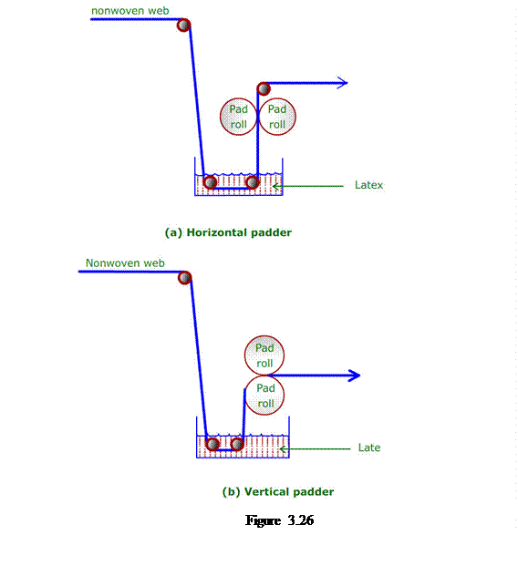 nonwoven web, hence reduces the thickness of the ultimate fabric.
Foam bonding process
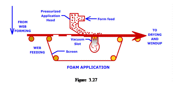
Figure 3.27 illustrates the foam bonding process. Here, air or water is used to dilute the binder and as a mean to carry the binder to the fibres. One advantage of diluting binder with air rather than with water is that drying is faster and energy cost is reduced remarkably. Foam is generated mechanically and can be stabilized with a stabilizing agent to prevent collapse during application. Foam can be applied so as to remain at the surface or can be made to penetrate all the way through the fabric cross-section. One or two reciprocating foam spreaders are commonly used to distribute the foam across the width of the fabric. The excess foam is sucked through the porous portion of the fabric and the perforations of the web carrying medium to the vacuum extractor as shown in Figure 7.3. The key advantage of foam bonding is more efficiency drying and the ability to control fabric softness. The disadvantages include the difficulty in achieving adequate foaming and in controlling the process to give a uniform binder distribution. Sometimes, non-stabilized foams, called froths, are formed.
 Spray bonding process
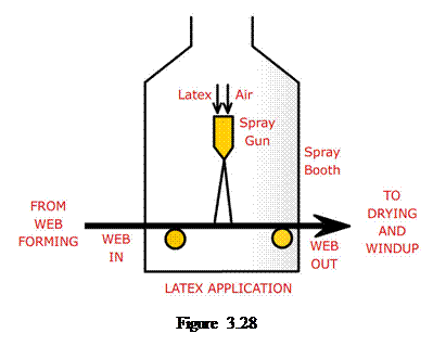
Figure 3.28 illustrates a typical spray bonding process. Here the binder is sprayed onto a moving web in fine droplet form through a system of nozzles, which can be statically mounted across the machine or transverse from one side to the other side of the machine. It is used to make highly porous and bulky products. This is possible because the substrate does not need to pass between nip rollers. The liquid is atomised by air pressure, hydraulic pressure, or centrifugal force and is applied to the upper surfaces of the web. The depth of penetration of the binder into the substrate depends on the wettability of the fibres, permeability of the web, and amount of binder. The main advantage of this method is that the nonwoven is not compressed and the original bulk and structure is retained. The disadvantages include lack of control of the uniformity of spraying, poor binder penetration, high level of overspray and waste, and possible lack of shear stability of the binder.
Print bonding process
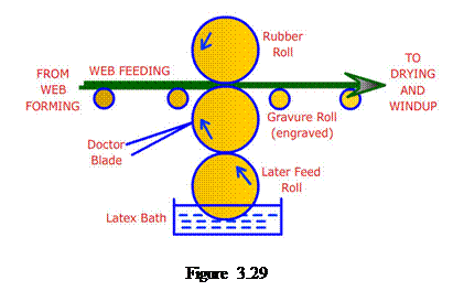 The print bonding process applies the binder only in predetermined areas as dictated by the pattern of the printing surfaces. Figure 3.29 displays the print bonding process where the latex is transferred to the web via feed roll and engraved roll. As the web passes the engraved roll, it is pressed against the surface by a rubber roll, transferring binder to the fabric. The excess latex is removed by a doctor blade. This method is suitable only for applying low levels of binder to the surface where a textile-like handle is needled.
Methods of drying
After the binder is applied, the web is dried to evaporate the latex carrier (water) and allow the latex particles to bond the nonwovens. Crosslinking (if crosslinking groups are present in the binder formulation) is usually carried out in the same dryer. During drying, film forming or coagulation takes place as well as evaporation of the water and cross-linking occurs. There are several types of dryers available such as drum dryer (Figure 3.30a), flat belt dryer (Figure 3.30b), stenter-based dryer (Figure 3.30c), and infrared dryer (Figure 3.30d). In drum or belt drying, the web is guided over a perforated conveyor surface through which hot air passes. Air is then withdrawn from the inside of the drum or through the perforations of the belt and mostly reused. The fabric shrinkage is one of important disadvantages of these methods. This can be overcome by stenter dryer. In infrared dryer, water is marked absorbed by infrared energy as it rapidly converts water into heat leading to evaporation. It requires less capital investment but high running cost. They are often used for pre-dry the surface to prevent the coating of binder on the first drum of a 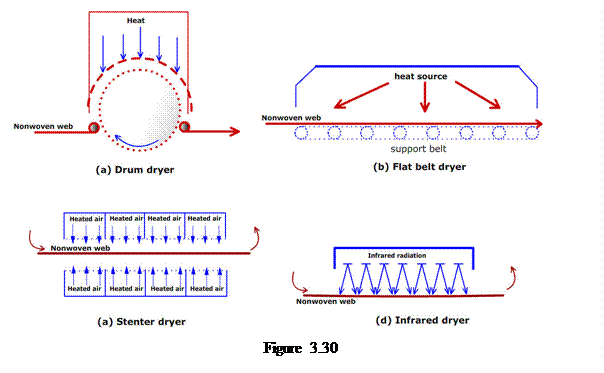 drum dryer and to coagulate the binder to prevent migration or post-dry the surface to complete crosslinking.
Applications
The chemical bonding process is used to develop nonwovens used as wipes, interlinings, hygiene and medical products, footwear, automotives, and homefurnishing products.
References
Source: http://www.nptel.ac.in/courses/116102014/text%20content/Module_3.doc
Web site to visit: http://www.nptel.ac.in
Author of the text: indicated on the source document of the above text
If you are the author of the text above and you not agree to share your knowledge for teaching, research, scholarship (for fair use as indicated in the United States copyrigh low) please send us an e-mail and we will remove your text quickly. Fair use is a limitation and exception to the exclusive right granted by copyright law to the author of a creative work. In United States copyright law, fair use is a doctrine that permits limited use of copyrighted material without acquiring permission from the rights holders. Examples of fair use include commentary, search engines, criticism, news reporting, research, teaching, library archiving and scholarship. It provides for the legal, unlicensed citation or incorporation of copyrighted material in another author's work under a four-factor balancing test. (source: http://en.wikipedia.org/wiki/Fair_use)
The information of medicine and health contained in the site are of a general nature and purpose which is purely informative and for this reason may not replace in any case, the council of a doctor or a qualified entity legally to the profession.
The texts are the property of their respective authors and we thank them for giving us the opportunity to share for free to students, teachers and users of the Web their texts will used only for illustrative educational and scientific purposes only.
All the information in our site are given for nonprofit educational purposes