
Positive Displacement Pumps has an expanding cavity on the suction side and a decreasing cavity on the discharge side. Liquid flows into the pumps as the cavity on the suction side expands and the liquid flows out of the discharge as the cavity collapses. The volume is constant given each cycle of operation.
The positive displacement pumps can be divided in two main classes
The positive displacement principle applies whether the pump is a
Positive Displacement Pumps, unlike a Centrifugal or Roto-dynamic Pumps, will produce the same flow at a given speed (RPM) no matter the discharge pressure.
A Positive Displacement Pump must not be operated against a closed valve on the discharge side of the pump because it has no shut-off head like Centrifugal Pumps. A Positive Displacement Pump operating against a closed discharge valve, will continue to produce flow until the pressure in the discharge line is increased until the line bursts or the pump is severely damaged - or both.
A relief or safety valve on the discharge side of the Positive Displacement Pump is therefore absolute necessary. The relief valve can be internal or external. The pump manufacturer has normally the option to supply internal relief or safety valves. The internal valve should in general only be used as a safety precaution, an external relief valve installed in the discharge line with a return line back to the suction line or supply tank is recommended.
Reciprocating Pumps
Typical reciprocating pumps are
Plunger pumps comprise of a cylinder with a reciprocating plunger in it. In the head of the cylinder the suction and discharge valves are mounted. In the suction stroke the plunger retracts and the suction valves opens causing suction of fluid into the cylinder. In the forward stroke the plunger push the liquid out the discharge valve.
With only one cylinder the fluid flow varies between maximum flow when the plunger moves through the middle positions, and zero flow when the plunger is in the end positions. A lot of energy is wasted when the fluid is accelerated in the piping system. Vibration and "water hammers" may be a serious problem. In general the problems are compensated by using two or more cylinders not working in phase with each other.
In diaphragm pumps the plunger pressurizes hydraulic oil which is used to flex a diaphragm in the pumping cylinder. Diaphragm valves are used to pump hazardous and toxic fluids.
Rotary Pumps
Typical rotary pumps are
In gear pumps the liquid is trapped by the opening between the gear teeth of two identical gears and the chasing of the pump on the suction side. On the pressure side the fluid is squeezed out when the teeth of the two gears are rotated against each other. The motor provides the drive for one gear.
The lobe pumps operates similar to the gear pump, but with two lobes driven by external timing gears. The lobes do not make contact.
Progressive cavity pumps consist of a metal rotor rotating within an elastomer-lined or elastic stator. When the rotor turns progressive chambers from suction end to
ANALYSIS OF RECIPROCATING PUMPS
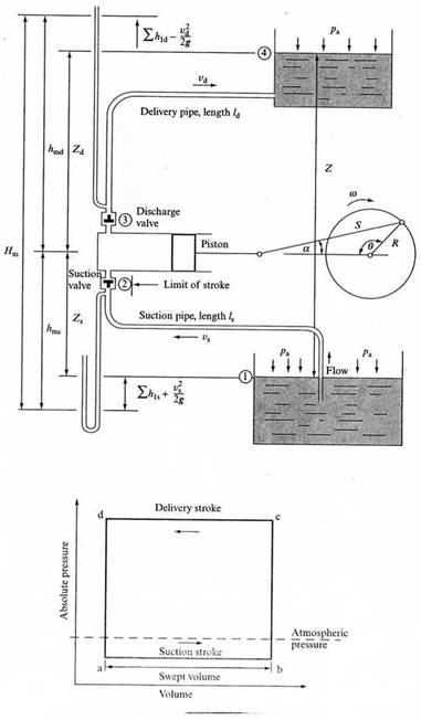
A reciprocating pump consists essentially of a piston moving to and fro in a cylinder. The piston is driven by a crank powered by some prime mover such as an electric motor, IC engine or steam engine. Small portable reciprocating pumps may be hand operated. Referring to the Fig. (a),
The above simplified analysis does not take into account the following effects:
Inertia effects
At the end of each stroke the liquid in the cylinder and in the relevant pipe must be brought to rest, i.e. decelerated. Immediately afterwards at the beginning of the following stroke, the fluid in the cylinder and in the associated pipe must be accelerated. These accelerations and decelerations result in additional pressures being involved. The inertia pressure may be given by:
![]() (1)
(1)
where ![]() is the length of the pipe and
is the length of the pipe and ![]() is the acceleration of the liquid. If the x-section of the cylinder is
is the acceleration of the liquid. If the x-section of the cylinder is ![]() and that of the pipe is
and that of the pipe is ![]() , then from the equation of continuity, we have
, then from the equation of continuity, we have
![]() , if
, if ![]() is the velocity of the piston, so that
is the velocity of the piston, so that
![]() (2)
(2)
Fig. (b): Basic pressure diagram for a reciprocating pump
Fig. (a): Reciprocating pump installation
and thus,
![]() . (3)
. (3)
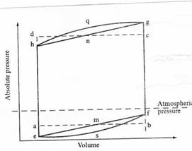
Thus at the beginning of the suction stroke (point a) (Fig. b) the liquid in the suction pipe must be accelerated so that the pressure in the cylinder must be lowered by an amount
![]() (4)
(4)
represented by the the distance ae on the digram. At the end of the suction stroke the same liquid in the suction pipe is decelerated so that it exerts pressure on the cylinder by an amount ![]() equal to
equal to ![]() .
.
Similarly the delivery stroke is affected at its beginning and its end by pressure changes:
![]() (5)
(5)
Consequently the inertia effects modify the simple pressure diagram abcd so that it becomes emfgnh (Figure c).
Fig. (c): Theoretical pressure diagram for a reciprocating pump
Friction Effect
The frictional losses in pipes are given by the Darcy equation
![]() (6)
(6)
And may be related to the piston velocity by substitution of v from the continuity equation
![]()
So that for the delivery stroke during which during which the frictional losses in the delivery pipe become relevant,
![]() (7)
(7)
Simple Harmonic Motion
Now, the piston velocity may be obtained from the displacement equation, assuming simple harmonic motion, in terms of the crank radius ![]() and crank angle
and crank angle ![]() and ultimately in terms of the angular velocity
and ultimately in terms of the angular velocity ![]() and time
and time ![]() , giving
, giving
![]() (8)
(8)
The equation shows that when ![]() = 0, i.e. at the beginning and end of the each stroke, u = 0 and therefore the frictional effects are zero, but the acceleration (or deceleration) du/dt is a maximum and hence the inertia effects are maximum. When
= 0, i.e. at the beginning and end of the each stroke, u = 0 and therefore the frictional effects are zero, but the acceleration (or deceleration) du/dt is a maximum and hence the inertia effects are maximum. When ![]() = 90o or 270o, i.e. at the middle of each stroke, the velocity is maximum and hence the frictional effects reach a maximum, whereas the acceleration (or deceleration) is zero and therefore, the inertia effects vanish.
= 90o or 270o, i.e. at the middle of each stroke, the velocity is maximum and hence the frictional effects reach a maximum, whereas the acceleration (or deceleration) is zero and therefore, the inertia effects vanish.
Also, it follows from Darcy equation that ![]() , so that curves esf and gqh representing frictional effects on the diagram are parabolae superimposed on lines emf and gnh. Thus the theoretical pressure diagram becomes esfgqh.
, so that curves esf and gqh representing frictional effects on the diagram are parabolae superimposed on lines emf and gnh. Thus the theoretical pressure diagram becomes esfgqh.
Volumetric Efficiency of the pump and Slip
The rate at which the liquid is delivered by the pump clearly depends upon the pump speed, since
Volume delivered in one stroke = ![]()
Where ![]() = piston stroke and
= piston stroke and ![]() = swept volume.
= swept volume.
Thus, if the pump speed is N (rev/min), then the theoretical volume delivered in 1 s is
![]()
And since ![]() ,
,
![]() (9)
(9)
Thus the pump discharge is directly proportional to the rotational speed and is entirely independent of the pressure against which the pump is delivering.
Because of the leakage of liquid through glands the actual pump discharge is smaller than the theoretical. If the leakage is ![]() then the actual delivery,
then the actual delivery,
![]() (10)
(10)
And the volumetric efficiency,
![]() (11)
(11)
Sometimes an expression known as slip is used:
Slip = ![]() (12)
(12)
Pump Pressure
The pump pressure depends upon the system against which it is working, as shown in Fig. (a), and may be obtained as follows. Applying the energy equation to points (1) and (4) and using the liquid level in the lower reservoir as datum,
Total energy at (1) + WD by pump = Total energy at (4) + Losses in the system
But
Total energy at (1) per unit mass of fluid flowing = ![]() ,
,
WD by the pump per unit mass of fluid flowing = gH (where H = pump head),
Total energy at (4) per unit mass of fluid flowing = gZ + pa/ρ,
Losses in the system = ![]()
Substituting,
![]()
Thus, rearranging, the pump head,
![]() (12)
(12)
It is sometimes useful to consider the pump suction side and pump delivery side separately. In this case, the static lift Z (the difference between the water levels if the reservoirs are open to atmosphere) is considered to be the sum of the suction lift Zs and delivery lift Zd, i.e.
Z = Zs + Zd.
If the difference in levels between the inlet and outlet is neglected (between (2) and (3) in the diagram) because it is usually very small compared with the rest of the system, the two sides of the pump may be analysed separately as follows.
Applying the steady flow energy equation between the lower reservoir (assuming constant water level) and the pipe at pump inlet (2),
![]() ,
,
from which the static pressure at pump inlet
 (13)
(13)
The expressions in the brackets is known as the manometric suction head, hms, because it represents the negative gauge pressure shown by a manometer attached to pump inlet.
Similarly applying the steady flow energy equation between the delivery pipe at the pump outlet (3) and the water level in the upper reservoir, the static pressure at pump outlet,
 (14)
(14)
Here the expression in brackets is the manometric delivery head, hmd, because it represents the gauge pressure shown by a manometer connected to the pump outlet.
The pump manometric head Hm is defined as:
![]() (15)
(15)
Therfore, substituting,
![]() (16)
(16)
Comparing equations (12) and (16),
![]()
If the delivery and suction pipes are of the same diameter, then vd = vs and H = Hm.
Efficiencies
The internal head, Hi, generated by the pump is greater than the pump head, H, the difference accounting for the internal losses within the pump, hlp. Thus,
Hi = H + hlp.
The internal fluid power generated by the pump is
![]() (17)
(17)
and the actual power output of the pump is
![]() (18)
(18)
If the power input to the pump from the prime mover is Po, then the overall pump efficiency is:
![]() (19)
(19)
Component efficiencies are also useful and they are as follows:
![]() (20)
(20)
It follows therefore that the overall pump efficiency,
![]()
so that
![]() (21)
(21)
When considering a pump installation an important limitation on the location of the pump, in relation to the level of the lower reservoir, is the manometeric suction head. It represents the lowest pressure in the system (at the pump inlet), in particular during the beginning of the suction stroke represented by point e in Fig. (c). If this pressure falls to the value of the liquid vapour pressure, cavitation will occur and delivery will cease (stop).
AIR VESSELS
One major disadvantage of reciprocating pumps is the fluctuating flow. It can be reduced by fitting air cylinders (air vessels) to either the suction pipe or the delivery pipe or both. Air cylinders are closed vessels which act similarly to surge tanks. The decelerating liquid moves into the cylinder (vessel) compressing the enclosed air and thus storing energy in it. When the fluid is accelerated the energy in the air is released, thus augmenting (increasing) the accelerating force. By this process the fluctuations in the flow are smoothed out to an extent dependent upon the size of the air vessels. Figure (d) shows an actual indicator diagram of a pump fitted with air cylinders. It shows that the effects of inertia have been largely eliminated.
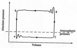
Fig. (d): Indicator diagram for a reciprocating pump with air vessels.
The provision of air chamber reduces the total friction loss to overcome in the system by maintaining a steady flow from the pump. Without the air chamber the work done against friction would vary with piston position and, as the flow-friction loss relationship is parabolic, the mean frictional resistance is two-thirds of the maximum, i.e. at mid-discharge stroke,
Mean friction loss = ![]() (22)
(22)
With an air-vessel close to the pump, so that the inertia effects in the short connecting pipe may be ignored, then
Mean friction loss = ![]() Constant flow-based loss
Constant flow-based loss
![]() (23)
(23)
Therefore,
![]() (24)
(24)
Another method of dealing with the fluctuations in the flow is the use of multi-cylinder pumps. In these several cylinders act in parallel and out of phase as shown in Fig. (e).
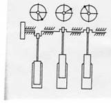
Fig. (e): Three-cylinder, single acting ram pump
A less effective solution is provided by a double-acting pump in which both sides of the piston are connected to the suction and delivery pipes and both sides of the piston work on the fluid. When one side is on suction stroke the other side at the same time is on the delivery stroke.
Figure (f) compares the flow rate fluctuations and the mean deliveries of single acting, double-acting and and two-cylinder, double-acting pumps
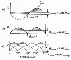
Fig. (f): Variation of discharge with crank angle θ for
The theoretical plot of the pump head H against flow rate Q at a constant speed is a vertical straight line as shown in Fig. (g). However, as the head against which the pump is working is increased the flow rate is in practice slightly reduced because of internal leakage.
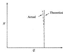
Fig. (g): Characteristic of a reciprocating pump
PROBLEM:
A single-acting, single-cylinder, positive displacement pump is used to drain an excavation. The pump has a bore of 150 mm and a stroke of 400 mm. The suction and discharge pipes are both of 50 mm diameter, the suction pipe being 2 m long and the discharge pipe 15 m long. The suction lift to the pump is 1.5 m while the discharge is 6 m above the level of the water surface in excavation. In the absence of any air chambers on either (a) pump suction or (b) discharge, Calculate for (a,b) the absolute pressure head in the cylinder at the
(i) start
(ii) end and
(iii) middle of each stroke if the pump drive is at 0.2 rev/s and may be assumed to be simple harmonic.
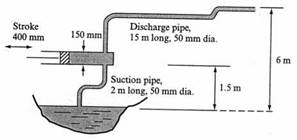
Also, determine (c) the maximum pump speed if separation is to be avoided on the piston face.
Assume a friction factor of 0.01 for both pipes, a pump slip of 4 per cent, an atmospheric pressure of 10.3 m of water, and a fluid vapour pressure of 2.4 m.
(d) For the above data of the reciprocating pump, calculate the increase in pump speed in rev/min if a large air chamber (vessel) were fitted close to the pump suction valve.
[ Hint: A general expression for the absolute head in cylinder during the suction stroke is written as:
![]()
Atmospheric Suction Suction Friction in suction
Pressure lift acceleration pipe
During discharge, the same form of equation mau be employed:
![]()
Atmospheic Delivery Delivery Delivery
Pressure lift acceleration pipe friction
Answers: (a) (i) 8.22 m of water (ii) 9.38 m of water (iii) 8.38 m of water
(b) (i) 19.15 m of water (ii) 10.45 m of water (iii) 17.68 m of water
Note that for delivery stroke, using the definition of Slip, (uA)actual = 0.96.(uA)theory. Therefore, vd = 0.96x(Aωr/a) is to be used in hdf.
(c) ω = 4.176 rad/s = 40 rev/min
(d) ω = 15.4 rad/s = 140 rev/min; Increase in speed = 100 rev/min]
Source: http://portal.unimap.edu.my/portal/page/portal30/Lecturer%20Notes/KEJURUTERAAN_MEKATRONIK/SEM1_08_09/ENT483/RECIPROCATING%20PUMPS.DOC
Web site to visit: http://portal.unimap.edu.my/
Author of the text: indicated on the source document of the above text
If you are the author of the text above and you not agree to share your knowledge for teaching, research, scholarship (for fair use as indicated in the United States copyrigh low) please send us an e-mail and we will remove your text quickly. Fair use is a limitation and exception to the exclusive right granted by copyright law to the author of a creative work. In United States copyright law, fair use is a doctrine that permits limited use of copyrighted material without acquiring permission from the rights holders. Examples of fair use include commentary, search engines, criticism, news reporting, research, teaching, library archiving and scholarship. It provides for the legal, unlicensed citation or incorporation of copyrighted material in another author's work under a four-factor balancing test. (source: http://en.wikipedia.org/wiki/Fair_use)
The information of medicine and health contained in the site are of a general nature and purpose which is purely informative and for this reason may not replace in any case, the council of a doctor or a qualified entity legally to the profession.
The texts are the property of their respective authors and we thank them for giving us the opportunity to share for free to students, teachers and users of the Web their texts will used only for illustrative educational and scientific purposes only.
All the information in our site are given for nonprofit educational purposes