
Power transmission is the movement of energy from its place of generation to a location where it is applied to performing useful work. Power transmission is normally accomplished by belts, ropes, chains, gears, couplings and friction clutches.
GEAR
A toothed wheel that engages another toothed mechanism in order to change the speed or direction of transmitted motion.
A gear is a component within a transmission device that transmits rotational force to another gear or device. A gear is different from a pulley in that a gear is a round wheel which has linkages ("teeth" or "cogs") that mesh with other gear teeth, allowing force to be fully transferred without slippage. Depending on their construction and arrangement, geared devices can transmit forces at different speeds, torques, or in a different direction, from the power source. The most common situation is for a gear to mesh with another gear
Gear’s most important feature is that gears of unequal sizes (diameters) can be combined
to produce a mechanical advantage, so that the rotational speed and torque of the second
gear are different from that of the first.
To overcome the problem of slippage as in belt drives, gears are used which produce positive drive with uniform angular velocity.
GEAR CLASSIFICATION
Gears or toothed wheels may be classified as follows:
1. According to the position of axes of the shafts.
The axes of the two shafts between which the motion is to be transmitted, may be
a. Parallel
b. Intersecting
c. Non-intersecting and Non-parallel
Gears for connecting parallel shafts
Teeth is parallel to axis of rotation can transmit power from one shaft to another parallel shaft. Spur gears are the simplest and most common type of gear. Their general form is a cylinder or disk. The teeth project radially, and with these "straight-cut gears".
Spur gears are gears in the same plane that move opposite of each other because they are meshed together. Gear ‘A’ is called the ‘driver’ because this is turned by a motor. As gear ‘A’ turns it meshes with gear ‘B’ and it begins to turn as well. Gear ‘B’ is called the ‘driven’ gear.

EXTERNAL AND INTERNAL SPUR GEAR
External gear makes external contact, and the internal gear (right side pair) makes internal contact.
APPLICATIONS OF SPUR GEAR
Electric screwdriver, dancing monster, oscillating sprinkler, windup alarm clock, washing machine and clothes dryer
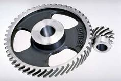
2. Parallel Helical Gear
The teeth on helical gears are cut at an angle to the face of the gear. When two teeth on a helical gear system engage, the contact starts at one end of the tooth and gradually spreads as the gears rotate, until the two teeth are in full engagement.
This gradual engagement makes helical gears operate much more smoothly and quietly than spur gears. For this reason, helical gears are used in almost all car transmissions. Because of the angle of the teeth on helical gears, they create a thrust load on the gear when they mesh. Devices that use helical gears have bearings that can support this thrust load.
One interesting thing about helical gears is that if the angles of the gear teeth are correct, they can be mounted on perpendicular shafts, adjusting the rotation angle by 90 degrees.
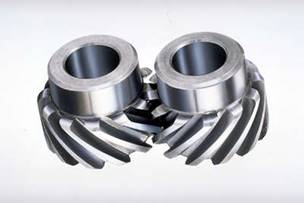
CROSSED HELICAL GEAR
Herringbone gears:
To avoid axial thrust, two helical gears of opposite hand can be mounted side by side, to cancel resulting thrust forces. These are called double helical or herringbone gears
Herringbone gears (or double-helical gears)
Applications of Herringbone Gears
The most common application is in power transmission. They utilize curved teeth for efficient, high capacity power transmission. This offers reduced pulsation due to which they are highly used for extrusion and polymerization. Herringbone gears are mostly used on heavy machinery.
3. Rack and pinion
Rack and pinion gears are used to convert rotation (From the pinion) into linear motion (of the rack). A perfect example of this is the steering system on many cars. The steering wheel rotates a gear which engages the rack. As the gear turns, it slides the rack either to the right or left, depending on which way you turn the wheel. Rack and pinion gears are also used in some scales to turn the dial that displays your weight.
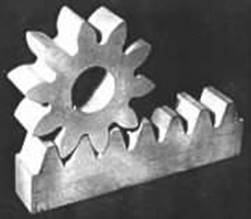
RACK AND PINION
GEARS FOR CONNECTING INTERSECTING SHAFTS
Bevel gears are useful when the direction of a shaft's rotation needs to be changed. They are usually mounted on shafts that are 90 degrees apart, but can be designed to work at other angles as well. The teeth on bevel gears can be straight, spiral or hypoid. Straight bevel gear teeth actually have the same problem as straight spur gear teeth as each tooth engages, it impacts the corresponding tooth all at once.
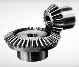
BEVEL GEAR
Just like with spur gears, the solution to this problem is to curve the gear teeth. These spiral teeth engage just like helical teeth: the contact starts at one end of the gear and progressively spreads across the whole tooth.
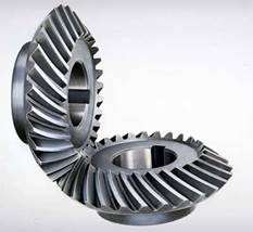
SPIRAL BEVEL GEAR
On straight and spiral bevel gears, the shafts must be perpendicular to each other, but they must also be in the same plane. If you were to extend the two shafts past the gears, they would intersect
The bevel gear has many diverse applications such as locomotives, marine applications, automobiles, printing presses, cooling towers, power plants, steel plants, railway track inspection machines, etc.
NON-INTERSECTING AND NON-PARALLEL
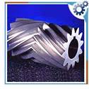
1. WORM AND WORM GEAR
Worm gears are used when large gear reductions are needed. It is common for worm gears to have reductions of 20:1, and even up to 300:1 or greater.
Many worm gears have an interesting property that no other gear set has: the worm can easily turn the gear, but the gear cannot turn the worm. This is because the angle on the worm is so shallow that when the gear tries to spin it, the friction between the gear and the worm holds the worm in place.
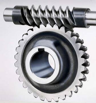
WORM AND WORM GEAR
This feature is useful for machines such as conveyor systems, in which the locking feature can act as a brake for the conveyor when the motor is not turning. One other very interesting usage of worm gears is in the Torsen differential, which is used on some high-performance cars and trucks. They are used in right-angle or skew shaft drives. The presence of sliding action in the system even though results in quieter operation, it gives rise to considerable frictional heat, hence they need good lubrication for heat dissipation and for improving the efficiency. High reductions are possible which results in compact drive.
APPLICATION OF WORM GEARS
Worm gears are used widely in material handling and transportation machinery, machine tools, automobiles etc.
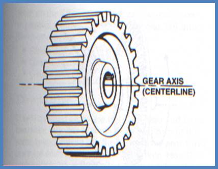
NOMENCLATURE OF SPUR GEARS
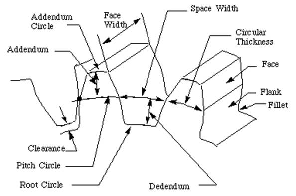
NOMENCLATURE OF SPUR GEAR
In the following section, we define many of the terms used in the analysis of spur gears.

![]()
Where
Pc = circular pitch
Pd = diametral pitch
N = number of teeth
D = pitch diameter
m = D/N
VELOCITY RATIO OF GEAR DRIVE
Velocity ratio is defined as the ratio of the speed of the driven shaft to the speed of the driver shaft.
One gear is a driver, which has d1, N1, ![]() 1 as diameter, speed and angular speed respectively. Another gear is driven connected to the driven shaft has d2, N2 ,
1 as diameter, speed and angular speed respectively. Another gear is driven connected to the driven shaft has d2, N2 ,![]() 2 as diameter, speed angular speed respectively.
2 as diameter, speed angular speed respectively.
Angular speeds of the two gears will be
![]()
![]()
The peripheral velocity of the driver and driven shafts for the meshing pair of gear is
equal and is given by ![]() =
= ![]() =
= ![]() =
= ![]()
Hence velocity ratio (n) = ![]()
T1 and T 2 are the number of teeth on driver gear and driven gear, since the pair of gear
as the same module (m),then
![]() ;
; ![]()
and ![]()
GEAR TRAINS
A gear train is two or more gear working together by meshing their teeth and turning each other in a system to generate power and speed. It reduces speed and increases torque. To create large gear ratio, gears are connected together to form gear trains. They often consist of multiple gears in the train. The smaller gears are one-fifth of the size of the larger gear. Electric motors are used with the gear systems to reduce the speed and increase the torque. Electric motor is connected to the driving end of each train and is mounted on the test platform. The output end of the gear train is connected to a large magnetic particle brake that is used to measure the output torque.
Types of gear trains
Simple Gear Train
The most common of the gear train is the gear pair connecting parallel shafts. The teeth of this type can be spur, helical or herringbone. only one gear for each axis. The angular velocity is simply the reverse of the tooth ratio. The main limitation of a simple gear train is that the maximum speed change ratio is 10:1. For larger ratio, large sizes of gear trains are required. The sprockets and chain in the bicycle is an example of simple gear train. When the paddle is pushed, the front gear is turned and that meshes with the links in the chain. The chain moves and meshes with the links in the rear gear that is attached to the rear wheel. This enables the bicycle to move.
Simple and compound gear trains
Compound Gear Train
For large velocities, compound arrangement is preferred. Two keys are keyed to a single shaft. A double reduction train can be arranged to have its input and output shafts in a line, by choosing equal center distance for gears and pinions. Two or more gears may rotate about a single axis
Planetary Gear Train (Epicyclic Gear Train)
Planetary gears solve the following problem. Let's say you want a gear ratio of 6:1 with the input turning in the same direction as the output. One way to create that ratio is with the following three-gear train:
Planetary Gear Train
In this train, the blue gear has six times the diameter of the yellow gear (giving a 6:1 ratio). The size of the red gear is not important because it is just there to reverse the direction of rotation so that the blue and yellow gears turn the same way. However, imagine that you want the axis of the output gear to be the same as that of the input gear. A common place where this same-axis capability is needed is in an electric screwdriver. In that case, you can use a planetary gear system, as shown here:

Planetary Gear Train
![]() In this gear system, the yellow gear (the sun) engages all three red gears (the planets) simultaneously. All three are attached to a plate (the planet carrier), and they engage the inside of the blue gear (the ring) instead of the outside. Because there are three red gears instead of one, this gear train is extremely rugged. The output shaft is attached to the blue ring gear, and the planet carrier is held stationary -- this gives the same 6:1 gear ratio. Another interesting thing about planetary gear sets is that they can produce different gear ratios depending on which gear you use as the input, which gear you use as the output, and which one you hold still. For instance, if the input is the sun gear, and we hold the ring gear stationary and attach the output shaft to the planet carrier, we get a different gear ratio. In this case, the planet carrier and planets orbit the sun gear, so instead of the sun gear having to spin six times for the planet carrier to make it around once, it has to spin seven times. This is because the planet carrier circled the sun gear once in the same direction as it was spinning, subtracting one revolution from the sun gear. So in this case, we get a 7:1 reduction.
In this gear system, the yellow gear (the sun) engages all three red gears (the planets) simultaneously. All three are attached to a plate (the planet carrier), and they engage the inside of the blue gear (the ring) instead of the outside. Because there are three red gears instead of one, this gear train is extremely rugged. The output shaft is attached to the blue ring gear, and the planet carrier is held stationary -- this gives the same 6:1 gear ratio. Another interesting thing about planetary gear sets is that they can produce different gear ratios depending on which gear you use as the input, which gear you use as the output, and which one you hold still. For instance, if the input is the sun gear, and we hold the ring gear stationary and attach the output shaft to the planet carrier, we get a different gear ratio. In this case, the planet carrier and planets orbit the sun gear, so instead of the sun gear having to spin six times for the planet carrier to make it around once, it has to spin seven times. This is because the planet carrier circled the sun gear once in the same direction as it was spinning, subtracting one revolution from the sun gear. So in this case, we get a 7:1 reduction.
You could rearrange things again, and this time hold the sun gear stationary, take the output from the planet carrier and hook the input up to the ring gear. This would give you a 1.17:1 gear reduction. An automatic transmission uses planetary gear sets to create the different gear ratios, using clutches and brake bands to hold different parts of the gear set stationary and change the inputs and outputs.
Planetary gear trains have several advantages. They have higher gear ratios. They are popular for automatic transmissions in automobiles. They are also used in bicycles for controlling power of pedaling automatically or manually. They are also used for power train between internal combustion engine and an electric motor.
Applications
Gear trains are used in representing the phases of moon on a watch or clock dial. It is also used for driving a conventional two-disk lunar phase display off the day-of-the-week shaft of the calendar.
Velocity ratio of Gear trains
We know that the velocity ratio of a pair of gears is the inverse proportion of the diameters of their pitch circle, and the diameter of the pitch circle equals to the number of teeth divided by the diametral pitch. Also, we know that it is necessary for the mating gears to have the same diametral pitch so that to satisfy the condition of correct meshing. Thus, we infer that the velocity ratio of a pair of gears is the inverse ratio of their number of teeth.
For the ordinary gear trains we have (Fig a)
These equations can be combined to give the velocity ratio of the first gear in the train to the last gear:
![]()
![]()
Note:
Problems
Given data
D= 200 mm
N=10
Solution
m =D/N
200/10= 20
Module of the gear is 20
Given Data
D= 180 mm
N=14
Solution

PC = 40 mm
SHORT QUESTIONS
ESSAY TYPE QUESTIONS
References
Source: https://www.snscourseware.org/snsct/files/CW_589d6efd08615/Gears%20and%20Gear%20Trains.doc
Web site to visit: https://www.snscourseware.org
Author of the text: indicated on the source document of the above text
If you are the author of the text above and you not agree to share your knowledge for teaching, research, scholarship (for fair use as indicated in the United States copyrigh low) please send us an e-mail and we will remove your text quickly. Fair use is a limitation and exception to the exclusive right granted by copyright law to the author of a creative work. In United States copyright law, fair use is a doctrine that permits limited use of copyrighted material without acquiring permission from the rights holders. Examples of fair use include commentary, search engines, criticism, news reporting, research, teaching, library archiving and scholarship. It provides for the legal, unlicensed citation or incorporation of copyrighted material in another author's work under a four-factor balancing test. (source: http://en.wikipedia.org/wiki/Fair_use)
The information of medicine and health contained in the site are of a general nature and purpose which is purely informative and for this reason may not replace in any case, the council of a doctor or a qualified entity legally to the profession.
The texts are the property of their respective authors and we thank them for giving us the opportunity to share for free to students, teachers and users of the Web their texts will used only for illustrative educational and scientific purposes only.
All the information in our site are given for nonprofit educational purposes