
The Gnome was one of several rotary engines popular on fighter planes during World War I. In this type of engine, the crankshaft is mounted on the airplane, while the crankcase and cylinders rotate with the propeller.
Most often attributed to the American F.D.Farwell the rotary engine may have had an earlier beginning in a compressed-air engine worked out by the Australian pioneer Lawrence Hargrave some eight or nine years prior. It is certain, however, that the French brothers Seguin brought the engine into commercial and mechanical life based on the conceptions of one brother (Laurent). It was in 1907 that his 7-cyl rotary was born - and it came to be known as the Gnome. This engine was followed by a succession of designs by many manufacturers, most of which were successful.
We are accustomed to seeing someone swing the prop to start an engine. This was not always necessary because a crank could be engaged to the gear on the rear of the thrust plate and enough rotary motion could be generated to get the engine started. When you compare this with the starting of a radial or an inline the reason why rotaries started easier can be seen. In the case of the radial or inline, it was necessary to set the innards of the engine in motion. The rotary was started by rotating the engine. The mass of the rotary added to the starting function and assisted the effort. The rotary was its own inertial starter!
The rotary engine gained quick acceptance because of its remarkable power to weight ratio. The only comparable ratios came from the brilliant mind of an American, Charles Manly. He had, in the very early years of the 1900s, achieved P/W ratios that even rotaries did not match until 1916. His 5-cyl 4-stroke static radial gave a ratio of 2.4 lb per hp dry and 4.0 with all of its plumbing attached. How remarkable was his achievement can be seen in a comparison of the Wright's engine which delivered one hp per 15 lbs and the 1912 Gnome rotary of 80hp which had a 2.625 ratio. Manly did not produce his engine commercially: the brothers Seguin did.
That the rotary engine dominated the early years of aviation is evident - although there were some very fine engines extant such as the twins of Duthiel-Chalmers and Darracq, the Antoinette by Levavasseur, and those of Fiat.
The demise of the rotary came about for several reasons. Among the most important of these was the large rotating mass of the engine which produced gyroscopic forces. These forces had their useful features - if the pilot could master them before something happened to lessen his desire to fly. It provided the Sopwith Camel with remarkable turning power. However, the engine also delivered sharp torque reversals when the ignition was cut which was tough on the engine mounts and the airframe.
Another problem encountered by rotary engine designers was met when trying to meet the demand for greater power. The size of the engine could be expanded in only two directions: make it larger in circumference, make it more than one row (deeper). The problem with the first solution was that this just made the gyroscopic forces even more unmanageable. The second way out of the problem provided much the same effect and the rear bank of cylinders were hard to cool.
There are other reasons that would have tended against the use of the rotary into more modern times and the greatest of these would be its enormous appetite for oil. The fuel was mixed with air as it was introduced through a primitive "carburettor" - usually in the tail end of the crankshaft. Via this route it made its way to the crankcase where is picked up all of the oil that was loose. When the fuel mixture was introduced to the combustion chamber it was very much a mix of fuel, air, and castor oil.
The imperfect combustion of any engine is not equalled by that of a rotary. The castor oil, being the least combustible of the two liquids, was spewed out into the atmosphere. It would be but a short time before the whole of the slipstream area of the aeroplane would be well coated with castor oil. The pilot would be soaking up oil at a fairly rapid rate as well. It is arguable that the reason for cowling the engine had as much to do with trying to control the wildly spewing oil as it was to do with the concepts of streamlining. The usual practice was to direct the oil underneath the fuselage by opening up the bottom of the cowl.
However, a cowling is not a favourite item to a rotary. The cylinders are air-cooled. As has been mentioned, the use of two banks of cylinders caused trouble enough. The cowling made the engine much hotter that it liked. The reason for the cutout in the bottom of the cowl, then, was to direct the spray of oil as well as to aid in cooling the engine. Some of the cowlings of WWI aeroplanes show evidence of extra cooling openings being cut into them by mechanics in the field.
Many people remark about the pleasantness of the odour of burnt castor oil. Out in the open where one's exposure is contrasted with other scents, it can be an enjoyable sensation. It is still nice if you are saying, "bye-bye" to the pilot before you go back to your mechanic's tasks. But to sit behind an engine that is spraying you with un-burnt - as well as burnt - castor oil is quite another matter after a few hours. The oil is known for its purgative qualities. It would be impossible to expose oneself to such an atmosphere and not experience certain difficulties.
It is the need for cooling that is part of the reason that pilots 'blipped' their engines. One could not use a throttle on them because they had such great need of motion to keep them cool. That they were allowed to stop to descend is true but the combustion had ceased during that time. (Of course, starting them up again could be an exciting experience. If they were not too loaded with the explosive fuel mixture - they might do just that: explode. If badly loaded in one or two cylinders, the rough running could cause considerable concern before it cleared.)
Although the cowling did cause them to overheat, It also allowed them to produce greater power as the air trapped within the cowl was easier to "stir" with the cylinders than would be a stream of high velocity air directed at the front of the engine.
They were easy to start by diving to turn the prop - which turned the engine. And they have been known to run with the most awesome damage inflicted on one or more cylinders.
There are many stories about the gyroscopic forces and their ability to turn a sorely pressed pilot out of danger. The most engaging terms used to describe the turn of a Camel was said by Dick Day: "Why, it puts both eyes on the same side of your nose!"
Gnome Monosoupape
The Gnome differed from other engines in that the intake valve was located in the piston itself as was opened by a vacuum being formed in the cylinder during the intake cycle. The fuel gas mixture was admitted through the crankcase and sucked in by the vacuum as the piston moves downwards. Power was regulated by 'blipping' the ignition.
As the piston moves to the bottom of the cylinder, vacuum is lost and the inlet valve closes. The piston then moves upwards thus compressing the fuel air mixture. The ignition spark occurs before top dead centre.
The power stroke now begins, the piston being forced downwards by the pressure of the expanding gasses. The exhaust valve opens well before bottom dead centre.
This engine has a fairly long exhaust stroke. In order to improve power or efficiency, engine valve timing often varies from what one might expect.
A number of engines were designed this way, including the Gnome, Gnome Monosoupape, LeRhone, Clerget, and Bentley to name a few. It turns out there were some good reasons for the configuration:
Balance. Note that the crankcase and cylinders revolve in one circle, while the pistons revolve in another, offset circle. Relative to the engine mounting point, there are no reciprocating parts. This means there's no need for a heavy counterbalance.
Air Cooling. Keeping an engine cool was an ongoing challenge for early engine designers. Many resorted to heavy water cooling systems. Air cooling was quite adequate on rotary engines, since the cylinders are always in motion.
No flywheel. The crankcase and cylinders provided more than adequate momentum to smooth out the power pulses, eliminating the need for a heavy flywheel.
All these factors gave rotary engines the best power-to-weight ratio of any configuration at the time, making them ideal for use in fighter planes. Of course, there were disadvantages as well:
Gyroscopic effect. A heavy spinning object resists efforts to disturb it's orientation (A toy gyroscope demonstrates the effect nicely). This made the aircraft difficult to manoeuvre.
Total Loss Oil system. Centrifugal force throws lubricating oil out after it's first trip through the engine. It was usually castor oil that could be readily combined with the fuel. (The romantic-looking scarf the pilot wore was actually a towel used to wipe the slimy stuff off his goggles!)
The aircraft's range was thus limited by the amount of oil it could carry as well as fuel. Most conventional engines continuously re-circulate a relatively small supply of oil.
the radial engine
Master-and-articulating-rod Assembly
The master-and-articulating-rod assembly is used on X-type engines, radial-type engines, and on some V-type engines. The master rod is similar to any other connecting rod except that it is constructed to provide for the attachment of the articulated rods on the big end.
You can see in the illustration that this is a five-cylinder engine -- radial engines typically have anywhere from three to nine cylinders. The radial engine has the same sort of pistons, valves and spark plugs that any four-stroke engine has. The big difference is in the crankshaft.
Instead of the long shaft that's used in a multi-cylinder car engine, there is a single hub -- all of the piston's connecting rods connect to this hub. One rod is fixed, and it is generally known as the master rod. The articulated rods are fastened by knuckle pins to a flange around the master rod. Each articulated connecting rod has a bushing of nonferrous metal, usually bronze, pressed or shrunk into place to serve as a knuckle-pin bearing. The knuckle pins may be held tightly in the master-rod holes by press fit and lock plates or they may be of the full-floating type.
If the big end of the master rod is made of two pieces, the cap and the rod, the crankshaft is made of one solid piece. on the other hand, if the rod is made of one piece, then the crankshaft may be of either two-piece or three-piece construction. Regardless of the type of construction, the usual bearing surfaces must be supplied.
It should be understood that the type of connecting rod used in an engine depends largely on the cylinder arrangement. If the cylinders are arranged in a line parallel to the crankshaft, the connecting rod is similar to that used in most automobile engines. However, certain types of aircraft engines have a system of connecting rods connected to the same crankshaft bearing, called an articulating connecting-rod assembly. The main rod or master rod joins one of the pistons with the crankshaft, and the other rods, called articulating rods or link rods, connect the other pistons to this same master connecting rod.
the two stroke engine
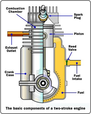
![]() Two-stroke engines do not have valves, which simplifies their construction and lowers their weight.
Two-stroke engines do not have valves, which simplifies their construction and lowers their weight.
![]() Two-stroke engines fire once every revolution, while four-stroke engines fire once every other revolution. This gives two-stroke engines a significant power boost.
Two-stroke engines fire once every revolution, while four-stroke engines fire once every other revolution. This gives two-stroke engines a significant power boost.
![]() Two-stroke engines can work in any orientation, which can be important in something like a chainsaw. A standard four-stroke engine may have problems with oil flow unless it is upright, and solving this problem can add complexity to the engine.
Two-stroke engines can work in any orientation, which can be important in something like a chainsaw. A standard four-stroke engine may have problems with oil flow unless it is upright, and solving this problem can add complexity to the engine.
These advantages make two-stroke engines lighter, simpler and less expensive to manufacture. Two-stroke engines also have the potential to pack about twice the power into the same space because there are twice as many power strokes per revolution. The combination of light weight and twice the power gives two-stroke engines a great power-to-weight ratio compared to many four-stroke engine designs.
The Two-stroke Cycle
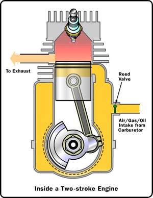
The following animation shows a two-stroke engine in action. The spark-plug fires once every revolution in a two-stroke engine.
This figure shows a typical cross flow design. You can see that two-stroke engines are ingenious little devices that overlap operations in order to reduce the part count.
You can understand a two-stroke engine by watching each part of the cycle. Start with the point where the spark plug fires. Fuel and air in the cylinder have been compressed, and when the spark plug fires the mixture ignites. The resulting explosion drives the piston downward. Note that as the piston moves downward, it is compressing the air/fuel mixture in the crankcase. As the piston approaches the bottom of its stroke, the exhaust port is uncovered. The pressure in the cylinder drives most of the exhaust gases out of cylinder, as shown here:
 |
As the piston finally bottoms out, the intake port is uncovered. The piston's movement has pressurized the mixture in the crankcase, so it rushes into the cylinder, displacing the remaining exhaust gases and filling the cylinder with a fresh charge of fuel, as shown here:
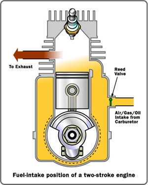 |
Note that in many two-stroke engines that use a cross-flow design, the piston is shaped so that the incoming fuel mixture doesn't simply flow right over the top of the piston and out the exhaust port.
Now the momentum in the crankshaft starts driving the piston back toward the spark plug for the compression stroke. As the air/fuel mixture in the piston is compressed, a vacuum is created in the crankcase. This vacuum opens the reed valve and sucks air/fuel/oil in from the carburettor.
Once the piston makes it to the end of the compression stroke, the spark plug fires again to repeat the cycle. It's called a two-stoke engine because there is a compression stroke and then a combustion stroke. In a four-stroke engine, there are separate intake, compression, combustion and exhaust strokes.
You can see that the piston is really doing three different things in a two-stroke engine:
![]() On one side of the piston is the combustion chamber, where the piston is compressing the air/fuel mixture and capturing the energy released by the ignition of the fuel.
On one side of the piston is the combustion chamber, where the piston is compressing the air/fuel mixture and capturing the energy released by the ignition of the fuel.
![]() On the other side of the piston is the crankcase, where the piston is creating a vacuum to suck in air/fuel from the carburettor through the reed valve and then pressurizing the crankcase so that air/fuel is forced into the combustion chamber.
On the other side of the piston is the crankcase, where the piston is creating a vacuum to suck in air/fuel from the carburettor through the reed valve and then pressurizing the crankcase so that air/fuel is forced into the combustion chamber.
![]() Meanwhile, the sides of the piston are acting like valves, covering and uncovering the intake and exhaust ports drilled into the side of the cylinder wall.
Meanwhile, the sides of the piston are acting like valves, covering and uncovering the intake and exhaust ports drilled into the side of the cylinder wall.
It's really pretty neat to see the piston doing so many different things! That's what makes two-stroke engines so simple and lightweight.
If you have ever used a two-stroke engine, you know that you have to mix special two-stroke oil in with the gasoline. Now that you understand the two-stroke cycle you can see why. In a four-stroke engine, the crankcase is completely separate from the combustion chamber, so you can fill the crankcase with heavy oil to lubricate the crankshaft bearings, the bearings on either end of the piston's connecting rod and the cylinder wall. In a two-stroke engine, on the other hand, the crankcase is serving as a pressurization chamber to force air/fuel into the cylinder, so it can't hold a thick oil. Instead, you mix oil in with the gas to lubricate the crankshaft, connecting rod and cylinder walls. If you forget to mix in the oil, the engine isn't going to last very long!
Many lightweight experimental aircraft use two stroke engines such as produced by Rotax.
diesel engines
Rudolf Diesel developed the idea for the diesel engine and obtained the German patent for it in 1892. His goal was to create an engine with high efficiency. Gasoline engines had been invented in 1876 and, especially at that time, were not very efficient.
The main differences between the gasoline engine and the diesel engine are:
![]() A gasoline engine intakes a mixture of gas and air, compresses it and ignites the mixture with a spark. A diesel engine takes in just air, compresses it and then injects fuel into the compressed air. The heat of the compressed air lights the fuel spontaneously.
A gasoline engine intakes a mixture of gas and air, compresses it and ignites the mixture with a spark. A diesel engine takes in just air, compresses it and then injects fuel into the compressed air. The heat of the compressed air lights the fuel spontaneously.
![]() A gasoline engine compresses at a ratio of 8:1 to 12:1, while a diesel engine compresses at a ratio of 14:1 to as high as 25:1. The higher compression ratio of the diesel engine leads to better efficiency.
A gasoline engine compresses at a ratio of 8:1 to 12:1, while a diesel engine compresses at a ratio of 14:1 to as high as 25:1. The higher compression ratio of the diesel engine leads to better efficiency.
![]() Gasoline engines generally use either carburetion, in which the air and fuel is mixed long before the air enters the cylinder, or port fuel injection, in which the fuel is injected just prior to the intake stroke (outside the cylinder). Diesel engines use direct fuel injection -- the diesel fuel is injected directly into the cylinder.
Gasoline engines generally use either carburetion, in which the air and fuel is mixed long before the air enters the cylinder, or port fuel injection, in which the fuel is injected just prior to the intake stroke (outside the cylinder). Diesel engines use direct fuel injection -- the diesel fuel is injected directly into the cylinder.
Note that the diesel engine has no spark plug, that it intakes air and compresses it, and that it then injects the fuel directly into the combustion chamber (direct injection). It is the heat of the compressed air that lights the fuel in a diesel engine.
The injector on a diesel engine is its most complex component and has been the subject of a great deal of experimentation -- in any particular engine it may be located in a variety of places. The injector has to be able to withstand the temperature and pressure inside the cylinder and still deliver the fuel in a fine mist. Getting the mist circulated in the cylinder so that it is evenly distributed is also a problem, so some diesel engines employ special induction valves, pre-combustion chambers or other devices to swirl the air in the combustion chamber or otherwise improve the ignition and combustion process.
One big difference between a diesel engine and a gas engine is in the injection process. Most car engines use port injection or a carburettor rather than direct injection. In a car engine, therefore, all of the fuel is loaded into the cylinder during the intake stroke and then compressed. The compression of the fuel/air mixture limits the compression ratio of the engine -- if it compresses the air too much, the fuel/air mixture spontaneously ignites and causes knocking. A diesel compresses only air, so the compression ratio can be much higher. The higher the compression ratio, the more power is generated.
Some diesel engines contain a glow plug of some sort (not shown in this figure). When a diesel engine is cold, the compression process may not raise the air to a high enough temperature to ignite the fuel. The glow plug is an electrically heated wire hat helps ignite the fuel when the engine is cold so that the engine can start. According to Cley Brotherton, a Journeyman heavy equipment technician:
All functions in a modern engine are controlled by the ECM communicating with an elaborate set of sensors measuring everything from R.P.M. to engine coolant and oil temperatures and even engine position (i.e. T.D.C.). Glow plugs are rarely used today on larger engines. The ECM senses ambient air temperature and retards the timing of the engine in cold weather so the injector sprays the fuel at a later time. The air in the cylinder is compressed more, creating more heat, which aids in starting.
the Wankel rotary engine
In a piston engine, pressure from the explosions drives pistons back and forth. In a rotary engine, the pressure drives a triangular rotor in a path around the inside of the chamber. As the rotor moves, it takes in air and fuel and compresses it. Spark plugs ignite the compressed fuel-and-air mixture, creating an explosion. The force of the explosion keeps the rotor moving. As it continues on the path, the rotor releases the exhaust and begins the cycle again.
Rotary engines have fewer moving parts that piston engines, so they are generally more reliable, and they operate more smoothly. But they are also less fuel-efficient as a rule, and they emit more pollution. A few aircraft, mostly experimental are now fitted with a Wankel engine.
the jet engine
A simplified view of how a jet engine works.
Before World War II, in 1939, jet engines existed only as laboratory items for test. But at the end of the war, in 1945, it was clear that the future of aviation lay with jets. The new engines gave great power and thrust, but were compact in size. They also were simple in their overall layout.
A jet engine, down to the present day, pulls in air by using a compressor. It looks like a short length of an ear of corn, but instead of corn kernels, the compressor is studded with numerous small blades. The compressor rotates rapidly, compressing the air.
The compressed air flows into a combustor. Here fuel is injected, mixed with this air, and burned. This heats the air to a high temperature. The hot, high-pressure air then passes through a turbine, forcing it to spin rapidly. The turbine draws power from this hot airflow. A long shaft connects the turbine and compressor; the spinning turbine uses its power to turn the compressor.
The jet-engine principle was known early in the twentieth century. However, jet engines work well only at speeds of at least several hundred miles per hour. Racing planes were the first to reach such speeds, with a British seaplane setting a record of 407 miles per hour (655 kilometres per hour) in 1931 and an Italian aircraft raising this record to 440 miles per hour (708 kilometres per hour) in 1934.
A young German physicist, Hans von Ohain, was in the forefront. He started by working on his own at Gottingen University. He then went to work for Ernst Heinkel, a plane builder who had a strong interest in advanced engines. Together they crafted the world's first jet plane, the experimental Heinkel He 178, which first flew on August 27, 1939.
The Jumo 004 jet engine of World War II. Its main features carried over to later engines.
Building on this work, the German engine designer Anselm Franz developed an engine suitable for use in a jet fighter. This airplane, the Me 262, was built by the firm of Messerschmitt. It was the only jet fighter to fly in combat during World War II. But the Me 262 spent most of its time on the ground because it used too much fuel. It was a sitting duck for Allied attacks.
Two Jumo 004 engines powered the Me 262. This was the first jet fighter to fly in combat and probably broke the sound barrier first. Because the Germans had not secured a source of chromium, the blades would stretch after a few hours making engine life very short indeed.
In England, Frank Whittle had no knowledge of Ohain's ideas but invented a jet engine completely on his own. The British drew on his work and developed a successful engine for another early jet fighter—the Gloster Meteor. Britain used it for homeland defence but it did not see combat over Germany because it lacked high speed.
The W.1 turbojet engine used to power the Gloster E28/39 aircraft. It was designed to produce a static thrust of 1,240 lbs at 17,750 rpm. This engine was also the basis of the design of the General Electric I-14 turbojet engine used to power the Bell XP-59A twin engine experimental fighter.
The British shared Whittle's technology with the United States, enabling the engine-builder General Electric (GE) to build jet engines for America's first jet fighter, the Bell XP-59. The aircraft company Lockheed then used a British engine in the initial version of its Lockheed P-80, America's first operational jet fighter, which entered service soon after the war's end. The British continued to develop new jet engines that used Whittle's designs, with Rolls-Royce initiating work on the Nene engine during 1944. Rolls sold Nenes to the Soviets, and a Soviet-built version of the engine subsequently powered the MiG-15 jet fighter that fought U.S. fighters and bombers during the Korean War.
The surrender of Germany, in 1945, unlocked a treasure trove of wartime discoveries and inventions. General Electric and Pratt & Whitney, another American engine-builder, added German lessons to those of Whittle and other British designers. Early jet engines, such as those of the Me 262, gulped fuel rapidly. Thus, an initial challenge involved building an engine that could give high thrust with less fuel consumption.
The J-31 (also known by its company designation, I-16) was the first turbojet engine produced in quantity in the United States. It was developed from the original American-built jet engine, the General Electric I-A, which was a copy of the highly secret British "Whittle" engine.
Pratt & Whitney solved this problem in 1948 with its "dual spool" concept. This combined two engines into one. The engine had two compressors—each rotated independently, with the inner one giving high compression for good performance. Each compressor drew power from its own turbine; hence there were two turbines, one behind the other. This approach led to the J-57 engine, which entered service with the U.S. Air Force in 1953.
The turboprop used power from a jet engine to drive a propeller. Additional turbines, placed near the exhaust, tapped this power and spun rapidly. An attached shaft delivered this power to a gearbox. Turboprops drew attention between 1945 and 1960 but lost out because jet aircraft were faster.
This was one of the outstanding post-war engines. It powered U.S. Air Force fighters, including the F-100, the first to break the sound barrier without going into a dive. Eight such engines powered the B-52 bomber. Commercial airliners—the Boeing 707, the Douglas DC-8—flew with it. This engine also saw use in the U-2 spy plane, which flew over the Soviet Union and photographed its military secrets.
Twin-spool jet engine (top) compared with a conventional design (below). Note that the twin-spool version has two compressors, each driven by its own turbine. This arrangement gave more thrust with better fuel economy.
The dual-spool engine represented an important step forward, but engine designers soon wanted more. As they reached for increasing performance, they ran into the problem of "compressor stall." This meant that at certain speeds while in flight, the compressor would pull in more air than the rest of the engine could swallow. Compressor stall produced a sudden blast of air that rushed forward within the engine. The engine lost all its thrust, while this air blast sometimes caused severe damage by breaking off compressor blades.
During the early 1950s, Pratt & Whitney rode merrily along with its J-57. Its competitor, GE, had a good engine of its own: the J-47, which powered the F-86 fighter and B-47 bomber. Still, GE's managers wanted something better. They got it from the engineer Gerhard Neumann, who found a way to eliminate compressor stall. Neumann introduced the "variable stator." This was a set of small vanes that protruded into the airflow within the compressor. Each such vane was like your hand that you stick into the outside air when you ride in a car. Like your hand, each vane could turn as if mounted to a wrist. When the vanes faced the airflow with their edges forward, they allowed the flow to pass them freely. But when the vanes were turned to present their broad faces to the flow, they partially blocked it. These vanes then reduced the amount of flow that was passing through the compressor, and kept it from gulping too much air.
Jet fighters gained speed by burning fuel within an afterburner. This was a tube fitted to the end of the jet engine. Exhaust from that engine contained a great deal of hot air and allowed fuel to burn within the afterburner, for more thrust.
This invention led to an important GE engine, the J-79. It became the first true engine for supersonic flight. With it, the Lockheed F-104 fighter flew at twice the speed of sound. In May 1958, U.S. Air Force pilots used this airplane to set a world speed record of 1,404 miles per hour (2,260 kilometres per hour) and an altitude record of 91,249 feet (27,813 meters). With supersonic flight in hand, the next frontier in jet-engine progress called for engines of very great power, suitable for aircraft of the largest possible size. The key concept proved to be the "turbofan," also called the "fanjet."
General layout of a turbofan engine. Note that a separate set of turbines drives the front fan, as in a turboprop. The term "high-bypass" means that most of the air in the exhaust comes from the fan and flows past the rest of the engine, rather than flowing through it.
The "jet" of a jet engine is the hot stream of exhaust that blasts out the back to produce thrust. However, that exhaust carries power as well as thrust, which the turbines use to run the compressor. By using a larger set of turbines, it is possible to tap off still more of this power. The big turbine then turns a fan, which somewhat resembles an airplane propeller but has many long blades set closely together. The fan adds its thrust to that of the jet. This arrangement yielded the turbofan. It more than doubled the thrust of earlier engines. It also further improved fuel economy. In addition, turbofan engines were relatively quiet, in contrast to earlier jets that produced loud shrieks and screams. GE and Pratt & Whitney both built turbofans after 1965, with Rolls-Royce, offering versions of its own. All truly large airliners have used them, starting with the Boeing 747. These engines have also powered large U.S. Air Force cargo planes, including the C-5A and C-17.
The first aircraft to use these large engines was the Lockheed C-5, which entered development in 1965 and first flew in 1968. A key to its design was the engine—the GE TF-39 turbofan. It had a dual-spool layout as well as a variable stator, with its big fan providing 85 percent of the thrust. The dual-spool arrangement gave the fan its own turbine for power, separate from the rest of the engine. The compressor had 16 stages, or rows of blades.
These three design principles—dual-spool layout, variable stators, and the turbofan—remain in use to this day. All three can even appear in the same engine, as with the TF-39. The dual-spool design gives high thrust with good fuel economy. Variable stators allow efficient operation at all flight speeds. The big forward fan reduces noise, further improves fuel economy, and produces much of the thrust. In turn, the thrust of engines continues to increase. Germany's engine for the wartime Me 262, the Jumo 004, delivered 2,000 pounds (8,900 Newtons) of thrust. The J-57 was rated at 13,500 pounds (60,000 Newtons) of thrust. The J-57 was similar in thrust but weighed considerably less, which made it much speedier. Early turbofans, around 1970, came in around 40,000 pounds (180,000 Newtons) of thrust. But GE's new GE 90 turbofan is rated at close to 90,000 pounds (400,000 Newtons) of thrust! That is why today's planes fly fast and are very large.
In the early 1990s, GE developed the GE90 turbofan engine to power the large, twin-engine Boeing 777. The GE90 family, with the baseline engine certified on the 777 in 1995, has produced a world's record thrust of 110,300 pounds in ground testing, has the world's largest fan at 123 inches in diameter, composite fan blades, and the highest engine bypass ratio (9:1) to produce the greatest propulsive efficiency of any commercial transport engine.
In this engine, air is sucked in from the right by the compressor. The compressor is basically a cone-shaped cylinder with small fan blades attached in rows (eight rows of blades are represented here). Assuming the light blue represents air at normal air pressure, then as the air is forced through the compression stage its pressure rises significantly. In some engines, the pressure of the air can rise by a factor of 30. The high-pressure air produced by the compressor is shown in dark blue.
the jet engine components
inlets
All turbine engines have an inlet to bring free stream air into the engine. The inlet sits upstream of the compressor and, while the inlet does no work on the flow, there are some important design features of the inlet. As shown in the figures above, inlets come in a variety of shapes and sizes with the specifics usually dictated by the speed of the aircraft.
subsonic inlets
For aircraft that cannot go faster than the speed of sound (like large airliners), a simple, straight, short inlet works quite well. On a typical subsonic inlet, the surface of the inlet, from outside to inside, is a continuous smooth curve with some thickness from inside to outside. The very front (most upstream portion) of the inlet is called the highlight, or the inlet lip. A subsonic aircraft has an inlet with a relatively thick lip.
supersonic inlets
An inlet for a supersonic aircraft, on the other hand, has a relatively sharp lip. The inlet lip is sharpened to minimize the performance losses from shock waves that occur during supersonic flight. For a supersonic aircraft, the inlet must slow the flow down to subsonic speeds before the air reaches the compressor. Some supersonic inlets, like the one at the upper right, use a central cone to shock the flow down to subsonic speeds. Other inlets, like the one shown at the lower left, use flat hinged plates to generate the compression shocks, with the resulting inlet geometry having a rectangular cross section. This kind of inlet is seen on the F-14 and F-15 fighter aircraft. There are other, more exotic inlet shapes used on some aircraft for a variety of reasons.
inlets efficiency
An inlet must operate efficiently over the entire flight envelope of the aircraft. At very low aircraft speeds, or when just sitting on the runway, free stream air is pulled into the engine by the compressor. In England, inlets are called intakes, which is a more accurate description of their function at low aircraft speeds. At high speeds, a good inlet will allow the aircraft to manoeuvre to high angles of attack and sideslip without disrupting flow to the compressor. Because the inlet is so important to overall aircraft operation, it is usually designed and tested by the airframe company, not the engine manufacturer. But because inlet operation is so important to engine performance, all engine manufacturers also employ inlet aerodynamicists.
compressors
All turbine engines have a compressor to increase the pressure of the incoming air before it enters the combustor.
As shown in the above figure, there are two main types of compressors: axial and centrifugal. The compressor on the left is called an axial compressor because the flow through the compressor travels parallel to the axis of rotation. The compressor on the right is called a centrifugal compressor because the flow through this compressor is turned perpendicular to the axis of rotation. Centrifugal compressors, which were used in the first jet engines, are still used on small turbojets and turboshaft engines and as pumps on rocket engines. Modern large turbojet and turbofan engines usually use axial compressors.
An axial flow compressor (stators omitted for clarity). This is the high pressure compressor from a General Electric F404 engine
Why the change to axial compressors? An average, single-stage, centrifugal compressor can increase the pressure by a factor of 4. A similar single-stage axial compressor increases the pressure by only a factor of 1.2. But it is relatively easy to link together several stages and produce a multistage axial compressor. In the multistage compressor, the pressure is multiplied from row to row (8 stages at 1.2 per stage gives a factor of 4.3). It is much more difficult to produce an efficient multistage centrifugal compressor because the flow has to be ducted back to the axis at each stage. Because the flow is turned perpendicular to the axis, an engine with a centrifugal compressor tends to be wider (greater cross-sectional area) than a corresponding axial. This creates additional undesirable aircraft drag. Centrifugal compressors are also less efficient than axial compressors. For all of these reasons, most high compression jet engines use multi staged axial compressors. But, if only a moderate amount of compression is required, a centrifugal compressor is much simpler to use.
combuster - burner
Combustion Chamber
The combustion chamber has the difficult task of burning large quantities of fuel, supplied through fuel spray nozzles, with extensive volumes of air, supplied by the compressor, and releasing the resulting heat in such a manner that the air is expanded and accelerated to give a smooth stream of uniformly heated gas. This task must be accomplished with the minimum loss in pressure and with the maximum heat release within the limited space available.
The amount of fuel added to the air will depend upon the temperature rise required. However, the maximum temperature is limited to within the range of 850 to 1700 °C by the materials from which the turbine blades and nozzles are made. The air has already been heated to between 200 and 550 °C by the work done in the compressor, giving a temperature rise requirement of 650 to 1150 °C from the combustion process. Since the gas temperature determines the engine thrust, the combustion chamber must be capable of maintaining stable and efficient combustion over a wide range of engine operating conditions.
The temperature of the gas after combustion is about 1800 to 2000 °C, which is far too hot for entry to the nozzle guide vanes of the turbine. The air not used for combustion, which amounts to about 60 percent of the total airflow, is therefore introduced progressively into the flame tube. Approximately one third of this gas is used to lower the temperature inside the combustor; the remainder is used for cooling the walls of the flame tube.
There are three main types of combustion chamber in use for gas turbine engines. These are the the multiple chamber, the can-annular chamber and the annular chamber.
Multiple chamber
This type of combustion chamber is used on centrifugal compressor engines and the earlier types of axial flow compressor engines. It is a direct development of the early type of Whittle engine combustion chamber. Chambers are disposed radially around the engine and compressor delivery air is directed by ducts into the individual chambers. Each chamber has an inner flame tube around which there is an air casing. The separate flame tubes are all interconnected. This allows each tube to operate at the same pressure and also allows combustion to propagate around the flame tubes during engine starting.
A multiple combustion chamber
Can-annular chamber
This type of combustion chamber bridges the evolutionary gap between multiple and annular types. A number of flame tubes are fitted inside a common air casing. The airflow is similar to that already described. This arrangement combines the ease of overhaul and testing of the multiple system with the compactness of the annular system.
A can-annular combustion chamber
Annular chamber
This type of combustion chamber consists of a single flame tube, completely annular in form, which is contained in an inner and outer casing. The main advantage of the annular combustion chamber is that for the same power output, the length of the chamber is only 75 per cent of that of a can-annular system of the same diameter, resulting in a considerable saving in weight and cost. Another advantage is the elimination of combustion propagation problems from chamber to chamber.
power turbine
The turbine has the task of providing power to drive the compressor and accessories. It does this by extracting energy from the hot gases released from the combustion system and expanding them to a lower pressure and temperature. The continuous flow of gas to which the turbine is exposed may enter the turbine at a temperature between 850 and 1700 °C which is far above the melting point of current materials technology.
A high-pressure turbine stage from a CFM56 turbofan engine
To produce the driving torque, the turbine may consist of several stages, each employing one row of stationary guide vanes, and one row of moving blades. The number of stages depends on the relationship between the power required from the gas flow, the rotational speed at which it must be produced, and the diameter of turbine permitted. The design of the nozzle guide vanes and turbine blade passages is broadly based on aerodynamic considerations, and to obtain optimum efficiency, compatible with compressor and combustor design, the nozzle guide vanes and turbine blades are of a basic aerofoil shape.
A turbine blade with cooling holes
The desire to produce a high engine efficiency demands a high turbine inlet temperature, but this causes problems as the turbine blades would be required to perform and survive long operating periods at temperatures above their melting point. These blades, while glowing red-hot, must be strong enough to carry the centrifugal loads due to rotation at high speed.
To operate under these conditions, cool air is forced out of many small holes in the blade. This air remains close to the blade, preventing it from melting, but not detracting significantly from the engine's overall performance. Nickel alloys are used to construct the turbine blades and the nozzle guide vanes because these materials demonstrate good properties at high temperatures.
nozzles
All gas turbine engines have a nozzle to produce thrust, to conduct the exhaust gases back to the free stream, and to set the mass flow rate through the engine. The nozzle sits downstream of the power turbine.
A nozzle is a relatively simple device, just a specially shaped tube through which hot gases flow. However, the mathematics which describe the operation of the nozzle takes some careful thought. As shown above, nozzles come in a variety of shapes and sizes depending on the mission of the aircraft. Simple turbojets, and turboprops, often have a fixed geometry convergent nozzle as shown on the left of the figure. Turbofan engines will sometimes employ a co-annular nozzle as shown at the top left. The core flow will exit the centre nozzle while the fan flow exits the annular nozzle. Afterburning turbojets and turbofans often have a variable geometry convergent-divergent (CD) nozzle as shown on the left. In this nozzle, the flow first converges down to the minimum area, or throat, then is expanded through the divergent section to the exit at the right. The variable geometry causes these nozzles to be heavy, but provides efficient engine operation over a wider airflow range than a simple fixed nozzle. Rocket engines usually have a fixed geometry CD nozzle with a much larger divergent section than is required for a gas turbine.
All of the nozzles we have discussed thus far are round tubes. Recently, however, engineers have been experimenting with nozzles with rectangular exits. This allows the exhaust flow to be easily deflected, as shown in the middle of the figure. Changing the direction of the thrust with the nozzle makes the aircraft much more manoeuvrable.
Because the nozzle conducts the hot exhaust back to the free stream, there can be serious interactions between the engine exhaust flow and the airflow around the aircraft. On fighter aircraft, in particular, large drag penalties can occur near the nozzle exits. A typical nozzle-afterbody configuration is shown in the upper right for an F-15 with experimental manoeuvring nozzles. As with the inlet design, the external nozzle configuration is often designed by the air-framer. The internal nozzle is usually the responsibility of the engine manufacturer.
turbojet engine
|
afterburning turbojet
To move an airplane through the air, thrust is generated by some kind of propulsion system. Most modern fighter aircraft employ an afterburner on either a low bypass turbofan or a turbojet. On this page we will discuss some of the fundamentals of an afterburning turbojet.
In order for fighter planes to fly faster than sound (supersonic), they have to overcome a sharp rise in drag near the speed of sound. A simple way to get the necessary thrust is to add an afterburner to a core turbojet. In a basic turbojet some of the energy of the exhaust from the burner is used to turn the turbine. The afterburner is used to put back some energy by injecting fuel directly into the hot exhaust. In the diagram below, you'll notice that the nozzle of the basic turbojet has been extended and there is now a ring of flame holders, coloured yellow, in the nozzle. When the afterburner is turned on, additional fuel is injected through the hoops and into the hot exhaust stream of the turbojet. The fuel burns and produces additional thrust, but it doesn't burn as efficiently as it does in the combustion section of the turbojet. You get more thrust, but you burn much more fuel. When the afterburner is turned off, the engine performs like a basic turbojet.
Afterburners are only used on supersonic aircraft like fighter planes and the Concorde supersonic airliner. (The Concorde turns the afterburners off once it gets into cruise. Otherwise, it would run out of fuel before reaching Europe.) Afterburners offer a mechanically simple way to augment thrust and are used on both turbojets and turbofans.
turbofan engine
Your browser does not support inline frames or is currently configured not to display inline frames.
Most modern airliners use turbofan engines because of their high thrust and good fuel efficiency. On this page, we will discuss some of the fundamentals of turbofan engines.
A turbofan engine is the most modern variation of the basic gas turbine engine. As with other gas turbines, there is a core engine. In the turbofan engine, the core engine is surrounded by a fan in the front and an additional turbine at the rear. The fan and fan turbine are composed of many blades, like the core compressor and core turbine, and are connected to an additional shaft.
As with the core compressor and turbine, some of the fan blades turn with the shaft and some blades remain stationary. The fan shaft passes through the core shaft for mechanical reasons. This type of arrangement is called a two spool engine (one "spool" for the fan, one "spool" for the core.) Some advanced engines have additional spools for even higher efficiency.
How does a turbofan engine work? The incoming air is captured by the engine inlet. Some of the incoming air passes through the fan and continues on into the core compressor and then the burner, where it is mixed with fuel and combustion occurs. The hot exhaust passes through the core and fan turbines and then out the nozzle, as in a basic turbojet. The rest of the incoming air passes through the fan and bypasses, or goes around the engine, just like the air through a propeller. The air that goes through the fan has a velocity that is slightly increased from free stream. So a turbofan gets some of its thrust from the core and some of its thrust from the fan. The ratio of the air that goes around the engine to the air that goes through the core is called the bypass ratio.
Because the fuel flow rate for the core is changed only a small amount by the addition of the fan, a turbofan generates more thrust for nearly the same amount of fuel used by the core. This means that a turbofan is very fuel efficient. In fact, high bypass ratio turbofans are nearly as fuel efficient as turboprops. Because the fan is enclosed by the inlet and is composed of many blades, it can operate efficiently at higher speeds than a simple propeller. That is why turbofans are found on high speed transports and propellers are used on low speed transports. Low bypass ratio turbofans are still more fuel efficient than basic turbojets. Many modern fighter planes actually use low bypass ratio turbofans equipped with afterburners. They can then cruise efficiently but still have high thrust when dog-fighting. Even though the fighter plane can fly much faster than the speed of sound, the air going into the engine must travel less than the speed of sound for high efficiency. Therefore, the airplane inlet slows the air down from supersonic speeds.
turboprop engine
Many low speed transport aircraft and small commuter aircraft use turboprop propulsion. On this page we will discuss some of the fundamentals of turboprop engines. The turboprop uses a gas turbine core to turn a propeller. As mentioned on a previous page, propeller engines develop thrust by moving a large mass of air through a small change in velocity. Propellers are very efficient and can use nearly any kind of engine to turn the prop (including humans!). In the turboprop, a gas turbine core is used. How does a turboprop engine work?
There are two main parts to a turboprop propulsion system, the core engine and the propeller. The core is very similar to a basic turbojet except that instead of expanding all the hot exhaust through the nozzle to produce thrust, most of the energy of the exhaust is used to turn the turbine. There may be an additional turbine stage present which is connected to a drive shaft. The drive shaft, also shown in green, is connected to a gear box. The gear box is then connected to a propeller that produces most of the thrust. The exhaust velocity of a turboprop is low and contributes little thrust because most of the energy of the core exhaust has gone into turning the drive shaft.
Because propellers become less efficient as the speed of the aircraft increases, turboprops are used only for low speed aircraft like cargo planes. High speed transports usually use high bypass turbofans because of the high fuel efficiency and high speed capability of turbofans. A variation of the turboprop engine is the turboshaft engine. In a turboshaft engine, the gear box is not connected
Source: http://www.thaiflyingclub.com/images/linkTFCfiles/groundschool/TFCtext08.Different%20Types%20of%20Engines.doc
Web site to visit: http://www.thaiflyingclub.com
Author of the text: indicated on the source document of the above text
If you are the author of the text above and you not agree to share your knowledge for teaching, research, scholarship (for fair use as indicated in the United States copyrigh low) please send us an e-mail and we will remove your text quickly. Fair use is a limitation and exception to the exclusive right granted by copyright law to the author of a creative work. In United States copyright law, fair use is a doctrine that permits limited use of copyrighted material without acquiring permission from the rights holders. Examples of fair use include commentary, search engines, criticism, news reporting, research, teaching, library archiving and scholarship. It provides for the legal, unlicensed citation or incorporation of copyrighted material in another author's work under a four-factor balancing test. (source: http://en.wikipedia.org/wiki/Fair_use)
The information of medicine and health contained in the site are of a general nature and purpose which is purely informative and for this reason may not replace in any case, the council of a doctor or a qualified entity legally to the profession.
The texts are the property of their respective authors and we thank them for giving us the opportunity to share for free to students, teachers and users of the Web their texts will used only for illustrative educational and scientific purposes only.
All the information in our site are given for nonprofit educational purposes