
Screw threads are cut with the lathe for accuracy and for versatility. Both inch and metric screw threads can be cut using the lathe. A thread is a uniform helical groove cut inside of a cylindrical workpiece, or on the outside of a tube or shaft. Cutting threads by using the lathe requires a thorough knowledge of the different principles of threads and procedures of cutting. Hand coordination, lathe mechanisms, and cutting tool angles are all interrelated during the thread cutting process. Before attempting to cut threads on the lathe a machine operator must have a thorough knowledge of the principles, terminology and uses of threads.
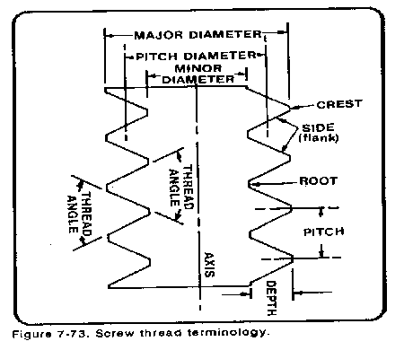
Screw Thread Terminology
The common terms and definitions below are used in screw thread work and will be used in discussing threads and thread cutting.
Screw Thread Forms
The most commonly used screw thread forms are detailed in the following paragraphs. One of the major problems in industry is the lack of a standard form for fastening devices. The screw thread forms that follow attempt to solve this problem; however, there is still more than one standard form being used in each industrial nation. The International Organization for Standardization (IS0) met in 1975 and drew up a standard metric measurement for screw threads, the new IS0 Metric thread Standard (previously known as the Optimum Metric Fastener System). Other thread forms are still in general use today, including the American (National) screw thread form, the square thread, the Acme thread, the Brown and Sharpe 29° worm screw thread, the British Standard Whitworth thread, the Unified thread, and different pipe threads. All of these threads can be cut by using the lathe.
The Brown and Sharpe 29° worm screw thread uses a 29° angle, similar to the Acme thread. The depth is greater and the widths of the crest and root are different (Table 7-9 in Appendix A). This is a special thread used to mesh with worm gears and to transmit motion between two shafts at right angles to each other that are on separate planes. This thread has a self-locking feature making it useful for winches and steering mechanisms.
The Unified and American (National) thread forms designate classifications for fit to ensure that mated threaded parts fit to the tolerances specified. The unified screw thread form specifies several classes of threads which are Classes 1A, 2A, and 3A for screws or external threaded parts, and 1B, 2B, and 3B for nuts or internal threaded parts. Classes 1 A and 1 B are for a loose fit where quick assembly and rapid production are important and shake or play is not objectionable. Classes 2A and 2B provide a small amount of play to prevent galling and seizure in assembly and use, and sufficient clearance for some plating. Classes 2A and 2B are recommended for standard practice in making commercial screws, bolts, and nuts. Classes 3A and 3B have no allowance and 75 percent of the tolerance of Classes 2A and 2B A screw and nut in this class may vary from a fit having no play to one with a small amount of play. Only high grade products are held to Class 3 specifications.
Four distinct classes of screw thread fits between mating threads (as between bolt and nut) have been designated for the American (National) screw thread form. Fit is defined as "the relation between two mating parts with reference to ease of assembly. " These four fits are produced by the application of tolerances which are listed in the standards.
The four fits are described as follows:
Thread Designations
In general, screw thread designations give the screw number (or diameter) first, then the thread per inch. Next is the thread series containing the initial letter of the series, NC (National Coarse), UNF (Unified Fine), NS (National Special), and so forth, followed by the class of fit. If a thread is left-hand, the letters LH follow the fit. An example of designations is as follows:
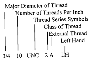
Two samples and explanations of thread designations are as follows:
Metric Thread Fit and Tolerance
The older metric screw thread system has over one hundred different thread sizes and several ways of designating the fit between parts, including tolerance grades, tolerance positions, and tolerance classes. A simple system was devised with the latest ISO Metric thread standard that uses one internal fit and two external fit designations to designate the tolerance (class) of fit. The symbol 6H is used to designate the fit for an internal thread (only the one symbol is used). The two symbols 6g and 5g6g are used to designate the fit for an external thread, 6g being used for general purpose threads and Sg6g used to designate a close fit. A fit between a pair of threaded parts is indicated by the internal thread (nut) tolerance fit designation followed by the external thread (bolt) tolerance fit designation with the two separated by a stroke. An example is M 5 x 0.8-Sg6g/6H, where the nominal or major diameter is 5 mm, the pitch is 0.8 mm, and a close fit is intended for the bolt and nut. Additional information on ISO metric threads and specific fits can be found in any updated engineer's handbook or machinist's handbook.
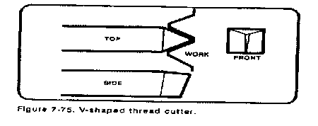
Cutting V-threads with a 60 degrees thread angle is the most common thread cutting operation done on a lathe. V-threads, with the 60 degree angle, are used for metric thread cutting and for American (National) threads and Unified threads. To properly cut V-shaped threads, the single point tool bit must be ground for the exact shape of the thread form, to include the root of the thread (Figure 7-75).
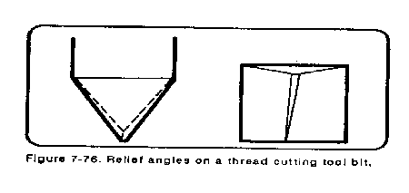
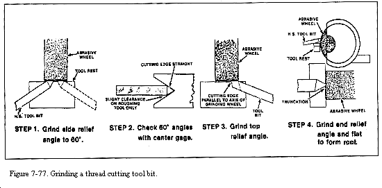
For metric and American (National) thread forms, a flat should be ground at the point of the tool bit (Figure 7-76), perpendicular to the center line of the 600 thread angle. See the thread form table for the appropriate thread to determine the width of the Sat. For unified thread forms, the tip of the tool bit should be ground with a radius formed to fit the size of the root of the thread. Internal unified threads have a flat on the tip of the tool bit. In all threads listed above, the tool bit should be ground with enough side relief angle and enough front clearance angle (Figure 7-76). Figure 7-77 illustrates the correct steps involved in grinding a thread-cutting tool bit.
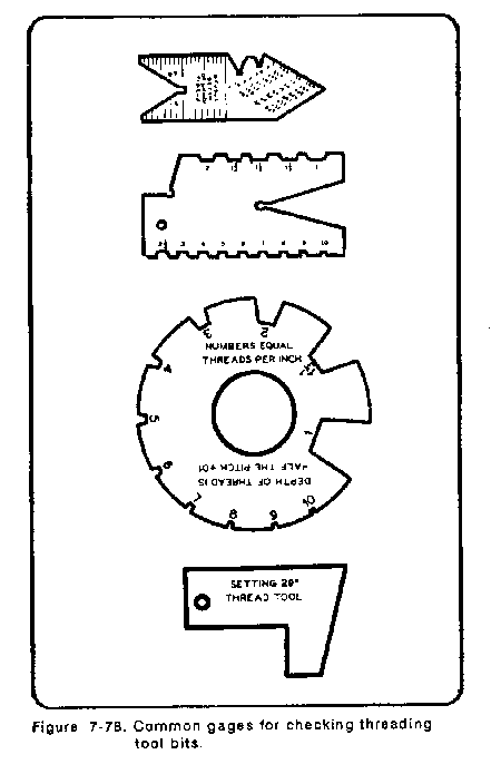
For Acme and 29° worm screw threads, the cutter bit must be ground to form a point angle of 29°. Side clearances must be sufficient to prevent rubbing on threads of steep pitch. The end of the bit is then ground to a flat which agrees with the width of the root for the specific pitch being cut. Thread-cutting tool gages (Figure 7-78) are available to simplify the procedure and make computations unnecessary.
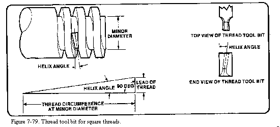
To cut square threads, a special thread-cutter bit is required. Before the square thread-cutter bit can be ground, it is necessary to compute the helix angle of the thread to be cut (Figure 7-79). Compute the helix angle by drawing a line equal in length to the thread circumference at its minor diameter (this is accomplished by multiplying the minor diameter by 3.1416 [pi]). Next, draw a line perpendicular to and at one end of the first line, equal in length to the lead of the thread. If the screw is to have a single thread, the lead will be equal to the pitch. Connect the ends of the angle so formed to obtain the helix angle.
The tool bit should be ground to the helix angle. The clearance angles for the sides should be within the helix angle. Note that the sides are also ground in toward the shank to provide additional clearance.
The end of the tool should be ground flat, the flat being equal to one-half the pitch of the thread to produce equal flats and spaces on the threaded part.
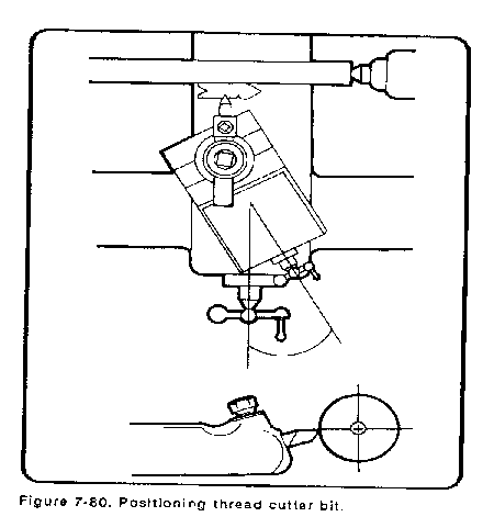
When positioning the thread-cutter bit for use, place it exactly on line horizontally with the axis of the workpiece. This is especially important for thread-cutter bits since a slight variation in the vertical position of the bit will change the thread angle being cut.
The thread-cutter bit must be positioned so that the centerline of the thread angle ground on the bit is exactly perpendicular to the axis of the workpiece. The easiest way to make this alignment is by use of a center gage. The center gage will permit checking the point angle at the same time as the alignment is being effected. The center gage is placed against the workpiece and the cutter bit is adjusted on the tool post so that its point fits snugly in the 60° angle notch of the center gage (Figure 7-80).
In cutting threads on a lathe, the pitch of the thread or number of threads per inch obtained is determined by the speed ratio of the headstock spindle and the lead screw which drives the carriage. Lathes equipped for thread cutting have gear arrangements for varying the speed of the lead screw. Modern lathes have a quick-change gearbox for varying the lead screw to spindle ratio so that the operator need only follow the instructions on the direction plates of the lathe to set the proper feed to produce the desired number of threads per inch. Once set to a specific number of threads per inch, the spindle speed can be varied depending upon the material being cut and the size of the workpiece without affecting the threads per inch.
The carriage is connected to the lead screw of the lathe for threading operations by engaging the half nut on the carriage apron with the lead screw. A control is available to reverse the direction of the lead screw for left or right-hand threading as desired. Be sure the lead screw turns in the proper direction. Feed the cutter bit from right to left to produce a right-hand thread. Feed the cutter bit from left to right to produce a left-hand thread.
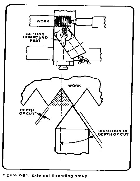
Direction of feed. For cutting standard 60° right-hand threads of the sharp V-type, such as the metric form, the American (National) form, and the Unified form, the tool bit should be moved in at an angle of 29° to the right (Figure 7-81). (Set the angle at 29° to the left for left-hand threads). Cutting threads with the compound rest at this angle allows for the left side of the tool bit to do most of the cutting, thus relieving some strain and producing a free curling chip. The direction is controlled by setting the compound rest at the 29° angle before adjusting the cutter bit perpendicular to the workpiece axis. The depth of cut is then controlled by the compound rest feed handle.
For Acme and 29° worm threads, the compound rest is set at one-half of the included angle (14 1/2°) and is fed in with the compound rest. For square threads, the cutter bit is fed into the workpiece at an angle perpendicular to the workpiece axis.
Before cutting threads, turn down the workpiece to the major diameter of the thread to be cut and chamfer the end. Engineering and machinist's handbooks have special tables listing the recommended major and minor diameters for all thread forms. These tables list a minimum and a maximum major diameter for the external threads, and a minimum and maximum minor diameter for internal threads. Table 7-10 in Appendix A lists the most common screw thread sizes. The difference between the maximum and minimum major diameters varies with different sizes of threads. Coarse threads have a larger difference between the two than fine threads. It is common practice, when machining threads on the lathe, to turn the outside diameter down to the maximum major diameter instead of the minimum major diameter, thus allowing for any error.
The workpiece may be set up in a chuck, in a collet, or between centers. If a long thread is to be cut, a steady rest or other support must be used to help decrease the chance of bending the workpiece. Lathe speed is set for the recommended threading speed (Table 7-2 in Appendix A).
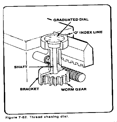
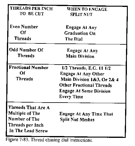
To cut threads, move the threading tool bit into contact with the work and zero the compound rest dial. The threading tool bit must be set at the right end of the work; then, move the tool bit in the first depth of cut by using the graduated collar of the compound rest. Position the carriage half nut lever to engage the half nut to the lead screw in order to start the threading operation. The first cut should be a scratch cut of no more than 0.003 inch so the pitch can be checked. Engaging the half nut with the lead screw causes the carriage to move as the lead screw revolves. Cut the thread by making a series of cuts in which the threading tool follows the original groove for each cut. Use the thread chasing dial, Figure 7-82, to determine when to engage the half nut so that the threading tool will track properly. The dial is attached to the carriage and is driven by means of the lead screw. Follow the directions of the thread chasing dial, Figure 7-83, to determine when to engage the half nut lever.
After making the first pass check for proper pitch of threads by using one of the three methods in Figure 7-84. After each pass of the threading tool bit, the operator must move the threading tool bit out of the threaded groove by backing out the compound rest handle, taking note of the setting. Traverse the carriage back to the start of the thread and move the compound rest dial back to the original setting plus the new depth of cut. At the end of each cut, the half nut lever is usually disengaged and the carriage returned by hand. (The cross slide dial can also be used to move the tool bit in and out, depending on the preference of the operator.)
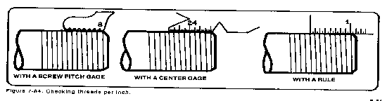
After cutting the first depth of thread, check for the proper pitch of threads by using one of the three methods in Figure 7-84. If the thread pitch is correct as set in the quick-change gearbox, continue to cut the thread to the required depth. This is determined by measuring the pitch diameter and checking the reference table for-the proper pitch diameter limits for the desired fit.
Some lathes are equipped with a thread chasing stop bolted to the carriage which can be set to regulate the depth of cut for each traverse of the cutter bit or can be set to regulate the total depth of cut of the thread.
When the thread is cut the end must be finished in some way. The most common means of finishing the end is with a specially ground or 45 degree angle chanifer cutting bit. To produce a rounded end, a cutter bit with the desired shape should be specially ground for that purpose.
Metric Thread Cutting Operations
Metric threads, are cut one of two ways by using the lathe, designed and equipped for metric measurement or by using a standard inch lathe and converting its operation to cut metric threads. A metric measurement lathe has a quick-change gear box used to set the proper screw pitch in millimeters. An inch-designed lathe must be converted to cut metric threads by switching gears in the lathe headstock according to the directions supplied with each lathe.
Most lathes come equipped with a set of changeable gears for cutting different, or nonstandard screw threads. Follow the directions in the lathe operator manual for setting the proper metric pitch. (A metric data plate may be attached to the lathe headstock.) Most lathes have the capability of quickly attaching these change gears over the existing gears then realigning the gearing. One change gear in needed for the lead screw gear and one for the spindle, or drive gear.
The metric thread diameter and pitch can be easily measured with a metric measuring tool. If there are no metric measuring tools available, the pitch and diameter must be converted from millimeters to inch measurement, and then a inch micrometer and measuring tools can be used to determine the proper pitch and diameter. Millimeters may be converted to inch measurement either by dividing millimeters by 25.4 inches or multiplying by 0.03937 inches.
For example, a thread with a designation M20 x 2.5 6g/6h is read as follows: the M designates the thread is metric. The 20 designates the major diameter in millimeters. The 2.5 designates the linear pitch in millimeters. The 6g/6h designates that a general purpose fit between nut and bolt is intended. Therefore, to machine this metric thread on a inch designed lathe, convert the outside diameter in millimeters to a decimal fraction of an inch and machine the major diameter to the desired diameter measurement. Convert the linear pitch in millimeters, to threads per inch by dividing the linear pitch of 2.5 by 25.4 to get the threads per inch (10.16 TPI).
Now. a 8-13 TPI thread micrometer can be used to measure the pitch diameter for this metric thread.
To sum up how to convert metric threads to inch measurement:
Set up the lathe for thread cutting as in the preceding paragraphs on screw thread cutting. Take a light trial cut and check that the threads are of the correct pitch using a metric screw pitch gage. At the end of this trial cut, and any cut when metric threading, turn off the lathe and back out the tool bit from the workpiece without disengaging the half-nut-lever. Never disengage the lever until the metric thread is cut to the proper pitch diameter, or the tool bit will have to be realigned and set for chasing into the thread.
After backing the tool bit out from the workpiece, traverse the tool bit back to the starting point by reversing the lathe spindle direction while leaving the half-nut lever engaged. If the correct pitch is being cut, continue to machine the thread to the desired depth.
NOTE: If the tool bit needs to be realigned and chased into the thread due to disengagement, of the half-nut lever or having to remove the piece and start again, then the lathe must be reset for threading. Start the lathe, with the tool bit clear of the workpiece engage the lever. Allow the carriage to travel until the tool bit is opposite any portion of the unfinished thread; and then turn off the lathe, leaving the engaged. Now the tool bit can be set back into a thread groove by advancing the cross slide and reference. Restart the lathe, and the tool bit should follow the groove that was previously cut, as long as the half-nut lever stays engaged.
Tapered screw threads or pipe threads can be cut on the lathe by setting the tailstock over or by using a taper attachment. Refer to the references for taper per inch and nominal measurements of tapered thread forms. When cutting a tapered thread, the tool bit should be set at right angles to the axis of the work. Do not set the tool bit at a right angle to the taper of the thread. Check the thread tool bit carefully for clearances before cutting since the bit will not be entering the work at right angles to the tapered workpiece surface.
The fit of the thread is determined by its pitch diameter. The pitch diameter is the diameter of the thread at an imaginary point on the thread where the width of the space and the width of the thread are equal. The fact that the mating parts bear on this point or angle of the thread, and not on the top of it, makes the pitch diameter an important dimension to use in measuring screw threads.
The thread micrometer (Figure 7-85) is an instrument used to gage the thread on the pitch diameter. The anvil is V-Shaped to fit over the V-thread. The spindle, or movable point, is cone-shaped (pointed to a V) to fit between the threads. Since the anvil and spindle both contact the sides of the threads, the pitch diameter is gaged and the reading is given on the sleeve and spindle where it can be read by the operator.
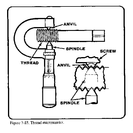
Thread micrometers are marked on the frame to specify the pitch diameters which the micrometer is used to measure. One will be marked, for instance, to measure from 8 to 13 threads per inch, while others are marked 14 to 20, 22 to 30, or 32 to 40; metric thread micrometers are also available in different sizes.
The procedure in checking the thread is first to select the proper micrometer, then calculate or select from a table of threads the correct pitch diameter of the screw. Lastly, fit the thread into the micrometer and take the reading.
The 3-wire method is another method of measuring the pitch diameter for American National (60 degree) and Unified threads. It is considered the "best" method for extremely accurate measurement. Appendix A shows three wires of correct diameter placed in threads with the micrometer measuring over them. The pitch diameter can be found by subtracting the wire constant from the measured distance over the wires. It can be readily seen that this method is dependent on the use of the "'best'" wire for the pitch of the thread. The "best" wire is the size of wire which touches the thread at the middle of the sloping sides. in other words, at the pitch diameter. A formula by which the proper size wire may be found is as follows: Divide the constant 0.57735 by the number of threads per inch to cut. If. for example, 8 threads per inch have been cut, we would calculate 0.57735 8 = 0.072. The diameter of wire to use for measuring an 8-pitch thread is 0.072.
The wires used in the three-wire method should be hardened and lapped steel wires. they, should be three times as accurate as the accuracy desired in measurement of the threads. The Bureau of Standards has specified an accuracy of 0.0002 inch. The suggested procedure for measuring threads is as follows:
After the three wires of equal diameter have been selected by using the above formula, they are positioned in the thread grooves as shown in Appendix A. The anvil and spindle of an ordinary micrometer are then placed against the three wires and the reading is taken. To determine what the reading of the micrometer should be if a thread is the correct finish size. use the following formula (for measuring Unified National Coarse threads): add three times the diameter of the wire to the diameter of the screw; from the sum, subtract the quotient obtained by dividing the constant 1.5155 by the number of threads per inch. Written concisely, the formula is:
![]()
Where m |
= |
micrometer measurement over wires, |
D |
= |
diameter of the thread, |
n |
= |
number of threads per inch, |
W |
= |
diameter of wire used |
Example: Determine m (measurement over wires) for 1/2 inch, 12-pitch UNC thread. We would proceed to solve as follows:
where W |
= |
0.04811 inch |
D |
= |
0.500 inch |
n |
= |
12 |
Then m |
= |
|
|
||
m |
= |
(0.500 + 0.14433) - 0.1263 |
|
||
m |
= |
0.51803 inch (micrometer measurement) |
When measuring a Unified National Fine thread, the same method and formula are used. Too much pressure should not be applied when measuring over wires.
Metric threads can also be checked by using the three-wire method by using different numerical values in the formula. Three-wire threads of metric dimensions must have a 60° angle for this method.
M |
= |
PD+ CPD = M-C |
|
||
M |
= |
measurement over the wires |
PD |
= |
pitch diameter |
C |
= |
N constant (This is found in Table 7-11 in Appendix A) |
The "best" wire size can be found by converting from inch to metric, or by using Table 7-11 in Appendix A.
An optical comparator must be used to check the threads if the tolerance desired is less than 0.001 inch (0.02 mm). This type of thread measurement is normally used in industrial shops doing production work.
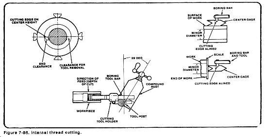
Internal threads are cut into nuts and castings in the same general manner as external threads. If a hand tap is not available to cut the internal threads, they must be machined on the lathe.
An internal threading operation will usually follow a boring and drilling operation, thus the machine operator must know drilling and boring procedures before attempting to cut internal threads. The same holder used for boring can be used to hold the tool bit for cutting internal threads. Lathe speed is the same as the speed for external thread cutting.
To prevent rubbing, the clearance of the cutter bit shank and boring tool bar must be greater for threading than for straight boring because of the necessity of moving the bit clear of the threads when returning the bit to the right after each cut.
The compound rest should be set at a 29° angle to the saddle so that the cutter bit will feed after each cut toward the operator and to his left.
Although the setup shown in Figure 7-86 would be impractical on extremely large lathes, it allows a degree of safety on common sized machines by having the compound ball crank positioned away from any work holding device that would be in use on the lathe, eliminating the possibility of the operator's hands or the compound rest contacting the revolving spindle and work holding devices.
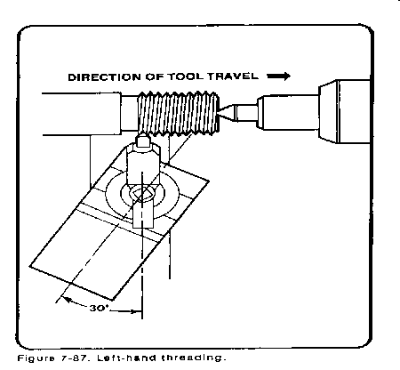
Cutting 60° left-hand threads. A left-hand thread is used for certain applications where a right-hand thread would not be practicable, such as on the left side of a grinder where the nut may loosen due to the rotation of the spindle. Left-hand threads are cut in the same manner as right hand threads, with a few changes. Set the feed direction lever so that the carriage feeds to the right, which will mean that the lead screw revolves opposite the direction used for right-hand threading. Set the compound rest 29° to the left of perpendicular. Cut a groove at the left end of the threaded section, thus providing clearance for starting the cutting tool (see Figure 7-87). Cut from left to right until the proper pitch dimension is achieved.
The first step is to grind a threading tool to conform to the 29° included angle of the thread. The tool is first ground to a point, with the sides of the tool forming the 29° included angle (Figure 7-88). This angle can be checked by placing the tool in the slot at the right end of the Acme thread gage.
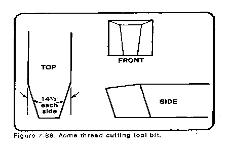
If a gage is not available, the width of the tool bit point may be calculated by the formula:
Width of point = 0.3707P - 0.0052 inch
Where P = Number of threads per inch
Be sure to grind this tool with sufficient side clearance so that it will cut. Depending upon the number of threads per inch to be cut, the point of the tool is ground flat to fit into the slot on the Acme thread gage that is marked with the number of threads per inch the tool is to cut. The size of the flat on the tool point will vary depending upon the thread per inch to be machined.
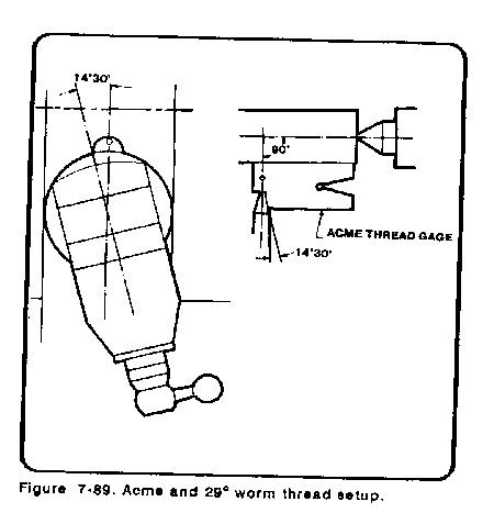
After grinding the tool, set the compound rest to one-half the included angle of the thread (14 1/2°) to the right of the vertical centerline of the machine (Figure 7-89). Mount the tool in the holder or tool post so that the top of the tool is on the axis or center line of the workpiece. The tool is set square to the work, using the Acme thread gage. This thread is cut using the compound feed. The depth to which you feed the compound rest to obtain total thread depth is determined by the formula given and illustrated in Table 7-9 in Appendix A. The remainder of the Acme thread-cutting operation is the same as the V-threading operation previously described. The compound rest should be fed into the work only 0.002 inch to 0.003 inch per cut until the desired depth of thread is obtained.
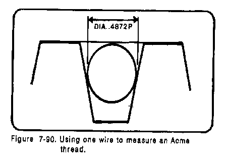
The formulas used to calculate Acme thread depth are in Table 7-9 in Appendix A. The single wire method can be used to measure the accuracy of the thread (Figure 7-90). A single wire or pin of the correct diameter is placed in the threaded groove and measured with a micrometer. The thread is the correct size when the micrometer reading over the wire is the same as the major diameter of the thread and the wire is placed tightly into the thread groove. The diameter of the wire to be used can be calculated by using this formula:
Wire diameter = 0.4872 x pitch
Thus, if 6 threads per inch are being cut, the wire size would be:
0.4872 x 1/6 = 0.081 inch
Cutting the 29° worm screw thread (Brown and Sharpe). The tool bit used to cut 29° worm screw threads will be similar to the Acme threading tool, but slightly longer with a different tip. Use Table 7-9 in Appendix A to calculate the length of the tool bit and tip width. The cutting is done just like cutting an Acme thread.
Because of their design and strength, square threads are used for vise screws, jackscrews, and other devices where maximum transmission of power is needed. All surfaces of the square thread form are square with each other, and the sides are perpendicular to the center axis of the threaded part. The depth, the width of the crest, and root are of equal dimensions. Because the contact areas are relatively small and do not wedge together, friction between matching threads is reduced to a minimum. This fact explains why square threads are used for power transmission.
Before the square thread cutting tool can be ground, it is necessary first to determine the helix angle of the thread. The sides of the tool for cutting the square thread should conform with the helix angle of the thread (Figure 7-79).
For cutting the thread, the cutting edge of the tool should be ground to a width exactly one-half that of the pitch. For cutting the nut, it should be from 0.001 to 0.003 of an inch larger to permit a free fit of the nut on the screw.
The cutting of the square thread form presents some difficulty. Although it is square, this thread, like any other, progresses in the form of a helix, and thus assumes a slight twist. Some operators prefer to produce this thread in two cuts, the first with a narrow tool to the full depth and the second with a tool ground to size. This procedure relieves cutting pressure on the tool nose and may prevent springing the work. The cutting operation for square threads differs from cutting threads previously explained in that the compound rest is set parallel to the axis of the workpiece and feeding is done only with the cross feed. The cross feed is fed only 0.002 inch or 0.003 inch per cut. The finish depth of the thread is determined by the formula.
Depth = 1/2P
Source: http://faculty.ksu.edu.sa/hossainy/Book1/Chapter%207.doc
Web site to visit:http://faculty.ksu.edu.sa
Author of the text: indicated on the source document of the above text
If you are the author of the text above and you not agree to share your knowledge for teaching, research, scholarship (for fair use as indicated in the United States copyrigh low) please send us an e-mail and we will remove your text quickly. Fair use is a limitation and exception to the exclusive right granted by copyright law to the author of a creative work. In United States copyright law, fair use is a doctrine that permits limited use of copyrighted material without acquiring permission from the rights holders. Examples of fair use include commentary, search engines, criticism, news reporting, research, teaching, library archiving and scholarship. It provides for the legal, unlicensed citation or incorporation of copyrighted material in another author's work under a four-factor balancing test. (source: http://en.wikipedia.org/wiki/Fair_use)
The information of medicine and health contained in the site are of a general nature and purpose which is purely informative and for this reason may not replace in any case, the council of a doctor or a qualified entity legally to the profession.
The texts are the property of their respective authors and we thank them for giving us the opportunity to share for free to students, teachers and users of the Web their texts will used only for illustrative educational and scientific purposes only.
All the information in our site are given for nonprofit educational purposes