
The steering system must provide control over the direction of travel of the vehicle; good manoeuvrability for parking the vehicle; smooth recovery from turns as the driver releases the steering wheel, minimum transmission of road shocks from the road surface and road wheel feed back.
The effort by the driver is transferred from the steering wheel, down the steering column, to a steering box. The steering box converts the rotary motion of the steering wheel, to the linear motion needed to steer the vehicle. It also gives the driver a mechanical advantage.
The linear motion from the steering box is then transferred by tie-rods, to the steering arms at the front wheels. The tie rods have ball joints that allow steering movement, and movement of the suspension. The steering-arm ball-joints are arranged so that movement in the suspension does not affect steering operation.
The direction of motion of a motor vehicle is controlled by a steering system. A basic steering system has 3 main parts:
When the driver turns the steering wheel, a shaft from the steering column turns a steering gear. The steering gear moves tie rods that connect to the front wheels. The tie rods move the front wheels to turn the vehicle right or left.
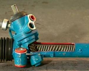
There are 2 basic types of steering boxes - those with rack-and-pinion gearing, and those with worm gearing. In both cases, the gearing in the steering box makes it easier for the driver to turn the steering wheel, and hence, the wheels.
A rack-and-pinion steering system has a steering wheel, a main-shaft, universal joints, and an intermediate shaft. When the steering is turned, movement is transferred by the shafts to the pinion. The pinion is meshed with the teeth of the rack, so pinion rotation moves the rack from side to side. This type of steering is used on passenger vehicles because it is light, and direct.
The steering rack is supported at the pinion end, by being sandwiched between the pinion and a spring-loaded, rack guide yoke. This spring-loaded yoke ensures free play is eliminated between the gears, while still allowing for relative movement.
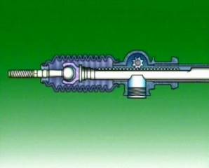
The rack is supported at the other end in the rack housing, or tube, by a bush, normally of nylon. Nylon is used because it has a low coefficient of friction, and is hard wearing. The pinion is supported by 2 bearings in the rack housing. These bearings are pre-loaded to keep the pinion in the correct position, relative to the rack, and to eliminate free play.
A rack-and-pinion steering box is normally lubricated by grease. Each end of the rack is protected from dirt and water by a flexible, synthetic, rubber bellows, attached to the rack housing and to the tie rod. The bellows extends and collapses, as the tie-rods move away from, and towards the housing, as the rack moves.
On some vehicles, both bellows are interconnected by a tube so that as the steering wheel is moved from side to side, air is transferred from the collapsing bellows side to the expanding bellows side.
Rack-and-pinion type steering gears are used because their construction makes them compact and light-weight. Their steering response is very sharp, because the rack operates directly on the steering knuckle. And there is very little sliding and rotation resistance, which gives lighter operation.
The rack-and-pinion steering gear box has a pinion, connected to the steering column. This pinion runs in mesh with a rack that is connected to the steering tie rods. This gives more direct operation. Both the pinion and the rack teeth are helical gears. Helical gearing gives smoother and quieter operation for the driver.
Turning the steering wheel rotates the pinion, and moves the rack from side to side. Ball joints at the end of the rack locate the tie-rods and allow movement in the steering and suspension.
Mechanical advantage is gained by the reduction ratio. The value of this ratio depends on the size of the pinion.
A small pinion gives light steering, but it requires many turns of the steering wheel to travel from lock, to lock. A large pinion means the number of turns of the steering column is reduced, but the steering is heavier to turn. Ratios vary, depending on the type of vehicle. But in each case, the ratio is the same for all positions of the wheels. It is a fixed ratio.
If an inclined plane is wrapped around a cylinder, the edge of the plane forms a shape called a helix.
Rotation of the cylinder causes a point on the helix to move, along the surface of the cylinder. The distance the point moves in one revolution of the cylinder is called the pitch.
The helix shape is commonly used as a thread on nuts and bolts, and also for teeth in steering gears, and transmissions.
A disadvantage of a fixed-ratio system is that towards the lock positions, more effort is needed by the driver.
This is because the angle of the steering arms reduces their effective length, and that reduces the leverage on the wheels.
To overcome this, many rack-and-pinion systems use variable ratio steering. The ratio is made variable by changing the shape of the teeth on the rack, between the centre and the outer edges of the rack.
Increased applications in front-wheel-drive of wider low-profile tyres place additional loads on front wheels. Steering then demands more effort from the driver.
Power steering helps to reduce the additional effort needed. It’s of most benefit during slow cornering and when parking.
5.0 Wheel Alignment
 All wheels of a vehicle must be correctly positioned, with the vehicle and with each other, for the vehicle to drive and steer properly.
A driver should not need to keep manipulating the steering wheel to maintain the vehicle in a straight-ahead position on straight, level roads. Similarly, little effort should be needed to turn the vehicle into curves, or to let it return to the straight-ahead position, when the curve has been negotiated. Wheels are installed on the suspension units at certain angles, to provide for these factors. These angles, taken together, are called wheel alignment.
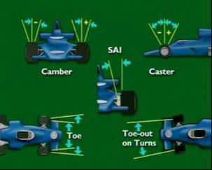
The factors that affect wheel alignment are:
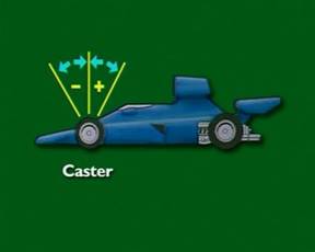
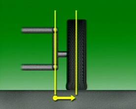
Seen from the side of the vehicle, the steering axis centreline is normally tilted from the vertical. Castor is the angle formed by this line, and a line drawn vertically through the centre of the wheel. Backward tilt from the vertical is positive castor. Forward tilt is negative castor.
 |
|
When a vehicle has positive castor, a line drawn through the steering axis centreline meets the road surface, ahead of the centreline of the wheel. The tyre contact point is behind the steering axis. When the wheel is turned to the right, the tyre contact point is moved to the left of the direction of travel and similarly for turning to the left.
In forward motion, this generates a self-cantering force which helps return the wheels to the neutral position when the steering wheel is released. The effects of positive castor can be seen in the motion of this furniture wheel. When it is acted on by a forward-moving force, its pivot point ahead of the wheel ensures the wheel always trails behind.
Most cars have positive castor, because it makes it easier to travel in a straight line with minimal driver action. But as positive castor increases, more and more effort is needed to turn the steering wheel.
Some vehicles have by design an amount of negative castor. Generally such vehicles would only operate at low speeds as vehicles with negative castor can become unstable as speed increases.
In all cases, the manufacturer’s specification should be followed.
A good steering system will always tend to maintain a straight course and to straighten out, or self centre, automatically after negotiating a corner. This self-centering action has to be overcome by the driver whenever the direction of the vehicle has to be changed. It therefore enables the driver to ‘feel’ the steering.
The self-centring effect is usually obtained by tilting the kingpin backwards at the top. The angle formed by the projected centre line of the king-pin and the vertical is called the castor angle, and the distance between the two lines at ground level is called castor trail. As the wheel is always being pulled along behind its pivot centre line, it always aligns itself in the direction being taken by the vehicle – centering itself in the same way as a castor of a dinner wagon does.
A steering road wheel which is also a driving wheel will not self centre—unless the kingpin is tilted in the opposite direction, i.e. forwards at the top. This reversal of the conventional angle is known as negative castor angle.
The castor angle varies between vehicles but is usually between 2° and 5°. Too large a castor angle produces steering which is hard to operate; too small a castor angle causes the vehicle to wander, and it may also cause wheel wobble.
The tilting of the kingpin may be obtained in leaf spring and beam axle arrangements by:
Where independent front suspension units are employed the whole assembly may be tilted in the original design. In other arrangements adjustments may be made through screwed bushes, or adjustable tie or torque rods, to obtain the same effect.
When the vehicle is moving, the force acting at the kingpin (to pull the wheel along) has to overcome the resistance of the wheel. If the kingpin and the wheel centre lines were parallel, and at 90° to the axle, these forces would act together (as a couple) to force the wheels to open outward or splay, the splaying effect being very greatly increased when the brakes were applied. In addition the wheel centre, being relatively distant from the kingpin, necessitates the wheel turning through an arc about the kingpin instead of about its own vertical centre line. This results in (a) a considerable effort being needed at the steering wheel and (b) large bending stresses being imposed on the stub axles and kingpins.
Heavy steering, splay, and very high stresses are reduced by, in effect, bringing the wheel and the kingpin centres closer together. This is done by tilting the wheel outwards at the top and the kingpin inwards at the top, reducing the radius of the arc through which the wheel has to swivel. The centre lines projected should meet at ground level; when they do, centre point steering is said to have been obtained. In practice, due to tyre spread, only approximate centre point steering can be obtained.
Camber is viewed from the front of the vehicle and it is the angle of tilt of the wheel from the vertical.
A wheel that leans away from the vehicle at the top is said to have positive camber. A wheel that leans towards the vehicle is said to have negative camber.
On modern vehicles, however, tyres are wider but they are generally smaller in diameter, and large camber angles would produce excessive wear on the outer edges of the tyres. The amount of camber is now reduced, so that most cars have what is called zero average camber, to give long tyre life.
This is because, when a vehicle is in motion, zero camber is difficult to maintain. Changes in running camber can be caused by road irregularities, and load variations.
Wheel camber is obtained by tilting the wheel outwards at the top. The camber angle is the angle formed between the centre line of the wheel and the vertical, and it is usually less than 2°. The tilting of
the wheel is obtained by inclining the horizontal centre line of the stub axle and results in the wheel describing a smaller arc about the kingpin at road level. This makes the wheel easier to swivel, and camber therefore provides lighter steering. It will also compensate for the effects of road camber and small suspension defects upon the steering. Because the centre line of the stub axle is inclined, the radius of the inner part of the tyre tread is greater than that of the outer part of the tread and this causes the wheel to run out, or splay when the vehicle is moving.
This splay action must be controlled by the track rod, which is therefore under compressive stress if fitted behind the axle, or under tensile stress if fitted in front of the axle. The difference between the radii also results in the inner bearing, which can easily be made the larger, being subjected to the heavier supporting load.
Under normal conditions, the effect upon the steering of the splay action of one wheel is counteracted or balanced by the splay action of the opposite wheel and the vehicle will run straight. If the camber angle at one side is greater than that at the other side the vehicle will pull over to the side having the greater camber angle. Due to the much greater splay forces, excessively large camber angles increase the wear on tyres and ball joints, and the stress on the track rod.
Kingpin inclination angle (K.P.I.)
The kingpin is tilted inwards at the top to assist in obtaining centre-point steering without excessive camber, i.e. assists the camber angle. The angle between the centre line of the kingpin and the vertical is known as the kingpin inclination angle (k.p.i.) and this is usually between 5° and 10°. The modern tendency is towards wheels of smaller diameter and, because it is essential to keep the camber angle small, the reduction of wheel diameter accompanies the use of larger kingpin inclination angles. Larger angles may also be used where longer stub axles are needed to permit the use of wider hub assemblies.
When the stub axle is moved from lock to lock, its end, due to the inclination of the kingpin, follows a curved path in the vertical plane. This results in the front end of the vehicle being lifted slightly as the wheels swivel towards full lock. The weight of the front end therefore helps to return the wheels to the straight forward position, i.e. kingpin inclination also has self-centring action. The effects of the combined use of camber and kingpin inclination are to:
The sizes of the camber and kingpin inclination angles may be reduced slightly by employing dished wheels, the dishing allowing the wheel and tyre centre line to be brought closer to the kingpin centre line.
Scrub radius is also known as steering offset, and scrub geometry. It is the distance between 2 imaginary points on the road surface – the point of centre contact between the road surface and the tyre, and the point where the steering-axis centre-line contacts the road surface.
If these two points intersect at the centre of the tyre, at the road surface, then the scrub radius is zero. If they intersect below the road surface, scrub radius is positive. If they intersect above the road surface, scrub radius is negative.
The effect of scrub radius – positive or negative – is to provide a turning moment which attempts to turn the wheel away from the central position, when the vehicle is in motion.
If it has negative scrub radius, the front wheels again tend to move back, but this time, they toe-in. On front-wheel-drive vehicles, the opposite occurs. Positive scrub radius causes toe-in, and negative causes toe-out.
During braking, on any type of drive, if braking effort is greater on one side of the vehicle than the other, positive scrub radius will cause the vehicle to veer towards the side with the greater effort. Negative scrub radius will cause the vehicle to veer away from the side of greatest effort. How much it veers depends on the size of the scrub radius.
This is why, vehicles with a diagonal-split brake system have negative scrub radius built into the steering geometry. If one half of the brake system fails, then the vehicle will tend to pull up in a straight line. Since the offset of the wheel rim determines where the centreline of the tyre meets the road surface, it is important that the offset is not changed if wheels are being replaced.
The axis around which the wheel assembly swivels as it turns to the right or left is called the steering axis. It is formed by drawing a line through the upper and lower pivot points of the suspension assembly. Seen from the front of the car, it is tilted inward.
The angle formed between this line and the vertical, provides steering axis inclination angles. Steering axis inclination acts, with castor, to provide a self-centring of the front wheels.
When the wheels are in the straight-ahead position, the ends of the stub axles are almost horizontal. When the wheels turn to either side, the effect of steering axis inclination is to make the ends of the stub axle tend to move downward, but this is prevented by the wheel. The stub axle carrier then must move up, which raises the front of the vehicle.
When the steering wheel is released, the mass of the vehicle forces the stub carrier back down, which pushes the wheels back to a central position.
With a vertical steering axis, no self-centring would occur. The wheel would pivot on a radius with the steering axis as its centre. This would introduce a turning moment on the wheel, road shocks would be transmitted back to the steering wheel, and steering would be difficult to control. Steering axis inclination brings the pivot point close to the centre of the tyre contact patch at the road surface. It intersects with the camber line drawn through the tyre and the wheel.
If these 2 lines intersect at the centre of the tyre, at the road surface, then the vehicle is said to have zero offset, or zero scrub radius. If they intersect below the road surface, then it has positive offset or scrub radius. If they intersect above the road surface, then it has negative offset or scrub radius.
The angle between the steering axis inclination and the camber line is called the included angle. It is a diagnostic angle.
Since the steering axis inclination is not adjustable, if the camber angle is correct, then the steering axis inclination should also be correct, that is it should match the specification. SAI is also referred to as KPI (King Pin Inclination) on trucks and old cars with king pins instead of ball joints.
On a vehicle with Independent Rear Suspension, undertaking a front-wheel-only alignment is considered to be an inadequate procedure.
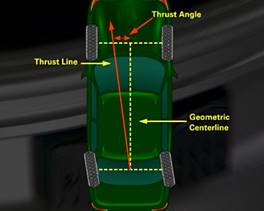
The thrust angle refers to all four wheels and their relationship to each other in addition to their relationship to an imaginary centreline that runs from each pair of wheels down the centre of the vehicle. The term “thrust line” refers to the direction in which the rear wheels are pointing. The thrust angle can be adjusted on vehicles with adjustable rear suspensions.
The thrust line may be in the same position as the vehicle’s geometric “centreline”; however there are variations to this. Ideally the thrust line and the vehicle’s geometric centreline should line up closely.
The “centreline” is drawn through point’s midway between each pair of wheels; however the thrust line is normally in the perpendicular position of the rear axle on solid axle cars, or, with IRS, is a line derived by splitting the toe angle of the rear wheels on the vehicle.
For instance, if the rear wheel on the right rear wheel side of the vehicle is toed-in six degrees, and the rear wheel on the left is at zero degrees, the thrust line will veer off three degrees to the left of the vehicle centreline at the rear wheels when the vehicle is moving forward.
An ideal situation is where the thrust and centrelines coincide. However, given the size of a vehicle, the tolerances during manufacture, operational stresses, and component wear; it’s rare that they do. If the deviation is very small, then remedial action is normally unnecessary. However, a large deviation can cause considerable concern when the vehicle is being driven. And the cause of this condition needs to be identified and corrected.
Under such conditions the rear wheels are steering the car away from its centreline and the driver has to turn the steering wheel to one side to keep the car going in a straight line. In extreme circumstances, the tracks the rear tyres make are beside those of the front. This condition is known as “crabbing” and can cause diagonal tyre pattern wear as well as vehicle instability in some driving conditions.
The thrust angle refers to all four wheels and their relationship to each other and to an imaginary centreline that runs from each pair of wheels down the centre of the vehicle. The term “thrust line” refers to the direction in which the rear wheels are pointing.
In order to provide effective control of the steering of the vehicle, and to reduce tyre and bearing wear, it is important that the wheels rotate, under all conditions, with a true rolling motion, i.e. free from side drag (tyre scrub).
When the vehicle is running straight, all the wheels should rotate truly automatically. When the vehicle has to negotiate a curve or a corner, the steering inner road wheel has to be swivelled through a larger angle than the outer wheel to maintain true rolling motion The difference between the two angles has to vary with the sharpness of the turn, and it must be provided both accurately and automatically. This is to ensure that each wheel is aligned at 90° to its own radius of turn, i.e. the line between the centre of the wheel and the centre of the turn. As near as practicable, these differences in swivelling angles are obtained by using the Ackerman system.
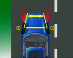
When the fronts of the wheels, as looking down upon the vehicle, are closer together than the rear of the wheels, it is called toe-in. The opposite arrangement is called toe-out.
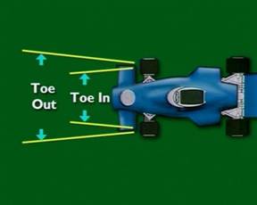
The static toe setting is designed to compensate for slight wear in steering connections, which may cause the wheels to splay outwards, or inwards. This means the wheels will be parallel when the vehicle is in motion, which avoids tyre scrub.
Toe-out on turns is the relative toe setting of the front wheels, as they turn to left, or right.
When a vehicle makes a turn, each wheel should rotate with true rolling motion that is free from tyre scrub.
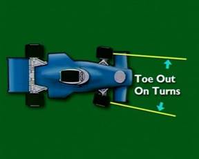
True rolling motion is only obtained when each wheel is at 90 degrees to a line drawn between the swivel axis and the centre of turn.
Because the rear wheels are fixed, the centre of turn will lie somewhere along the centreline of the rear axle, depending on how far the steering wheel is turned from the straight-ahead position.
To provide true rolling motion, the inner wheel must be turned through a greater angle than the outer wheel. This allows the inner wheel to turn through a smaller turning radius than the outer wheel.
This automatically correct alignment is obtained by use of the Ackerman principle and layout. With the steering linkage at the rear of the wheels, the distance across the tie-rod ends, at the steering arm joints, is made shorter than the distance across the steering axis swivels. This forces the inner wheel to turn through a larger angle when the steering is turned.
The Ackerman angle is the angle the steering arms make with the swivels, on the centreline of the vehicle, at or near the centre of the rear axle.
Oversteer is the tendency for a vehicle to turn into a corner more than necessary due to a loss of traction at the rear wheels. It is best described as a feeling that the rear of the vehicle wants to "swing out". Oversteer can be caused by a number of reasons such as excessively worn rear tyres, incorrect tyre pressures, vehicle drive train (rear wheel drive cars have a tendency towards oversteer), and vehicle weight balance (front to rear).
Understeer, also known as "push" or "pushing" is best described as the situation that occurs when the vehicle fails to sufficiently respond to the drivers steering input. It occurs when the front tyres do not have sufficient grip to carry out the cornering manoeuvre asked of them. Main cause of understeer include excessive cornering speed, wet / icy road conditions, incorrect tyre pressures and poor tyre condition (tread depth etc).
Understeer is, as the term suggests, the opposite of oversteer and it is generally accepted as preferable to oversteer for the average motorist. Most motorists will experience understeer at some point whilst driving and as opposed to oversteer, it is fairly predictable and relatively easy to overcome.
 For the road-wheels to roll freely and with the minimum of effort, opposite wheels must be approximately parallel to each other when the vehicle is in motion along a straight path.
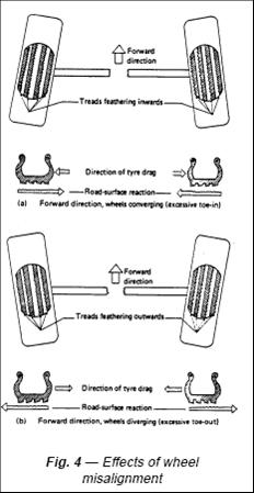
If the front wheels are aligned so that they are converging towards the front, then in the forward direction both wheels will be trying to roll closer together. Conversely, if the wheels are set so that they are diverging towards the front, the freerolling tendency will be for the wheels to move farther apart. In both cases the wheels will be restrained from moving closer or farther apart by the steering linkage, therefore the average path followed will mean that both wheels will have a continuous tendency to either push together or pull apart. Consequently, while rolling forward, each wheel will simultaneously be slipping laterally, so a continuous cross-tread scrub action is established, with the obvious results—excessive tread wear, heavy steering, and probably poor fuel consumption.
Examining a tyre tread subjected to excessive lateral slip or scrub will show a diagonal wear pattern, with the leading side of the tread blocks heavily worn and the trailing side having an extruded feather-like appearance.
Figure 4 (a) shows converging wheels with the characteristic inward feathering of the tread blocks.
Figure 4 (b) shows diverging wheels with the usual outward feathering of the tread blocks and grooves.
Correctly aligned and parallel-rolling wheels will produce an even wear pattern across the tyre tread.
The following should be examined and, if necessary corrected before carrying out steering geometry checks.
The vehicle should be parked on a smooth and level floor.
Optical gauge should be checked for accuracy.
Turning radius is a measure of how small a circle the vehicle can turn around in, when the steering wheel is turned to the limit.
All vehicles have stops to limit how far the front wheels can turn.
In some designs, these stops can be adjusted, as part of a wheel alignment. If the stops are incorrectly adjusted, they could allow too large a turning angle, and the steering box can be damaged.
Bushes, or bushings, act as bearings at suspension fulcrum points, to allow for movement of the component, while maintaining its alignment.
They can be metallic, or made of rubber, nylon, or urethane. In commercial vehicles, metallic bushes are commonly used as shackle bushes for leaf springs. Any force applied to the bush acts through it to the body of the vehicle, which results in a harsher ride. The mounting pin on a metallic bush is usually drilled to allow for lubricating the bushes.
Ball joints are swivel connections mounted in the outer ends of the front control arms, and on the steering track rods and tie-rods. They allow the control arms to move up and down with suspension deflection, and also let the wheel and hub assembly turn for steering.
The ball joint can be a sealed, self-contained unit, fastened to the control arm in a number of ways.
Source: http://local.ecollege.ie/Content/APPRENTICE/liu/hvm_notes/M8U2.doc
Web site to visit: http://local.ecollege.ie
Author of the text: indicated on the source document of the above text
If you are the author of the text above and you not agree to share your knowledge for teaching, research, scholarship (for fair use as indicated in the United States copyrigh low) please send us an e-mail and we will remove your text quickly. Fair use is a limitation and exception to the exclusive right granted by copyright law to the author of a creative work. In United States copyright law, fair use is a doctrine that permits limited use of copyrighted material without acquiring permission from the rights holders. Examples of fair use include commentary, search engines, criticism, news reporting, research, teaching, library archiving and scholarship. It provides for the legal, unlicensed citation or incorporation of copyrighted material in another author's work under a four-factor balancing test. (source: http://en.wikipedia.org/wiki/Fair_use)
The information of medicine and health contained in the site are of a general nature and purpose which is purely informative and for this reason may not replace in any case, the council of a doctor or a qualified entity legally to the profession.
The texts are the property of their respective authors and we thank them for giving us the opportunity to share for free to students, teachers and users of the Web their texts will used only for illustrative educational and scientific purposes only.
All the information in our site are given for nonprofit educational purposes