
STRESS INVOLVED CORROSION MECHANISMS.
The interaction of stress either applied or residual stresses accompanied by an aggressive environment can result in very large decreases in the expected mechanical properties of materials. Importantly the evidence for corrosion processes in these cases in the form of corrosion products is minimal. Examples of these processes include stress corrosion cracking (SCC), corrosion fatigue, fretting and hydrogen assisted environmental cracking or hydrogen embrittlement (HE). These all result in diminished mechanical properties.
STRESS CORROSION CRACKING.
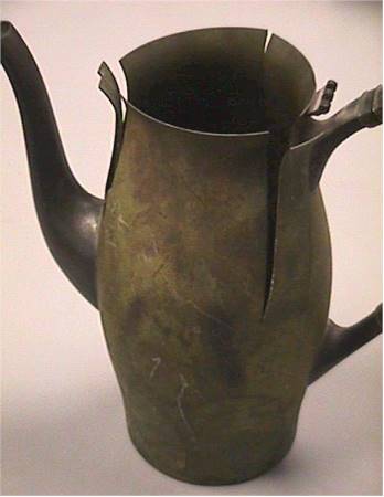
This is an important mechanism which produces failure in a metal. The process has been extensively researched. SCC depends on both an aggressive environment and a TENSILE stress. The tensile stress is required to open up cracks in the material. The stress can be either directly applied or residual in form. An example of residual stress resulting in stress corrosion cracking of brass is after deep drawing. Large hoop residual tensile stresses are present after the deep drawing process. If an aggressive environment is placed on the brass, cracks will appear due to the conjoint action of the stress and the environment. In its early days this was called "season cracking" as it occurred during the monsoon season in India on brass bullets and cartridge shells due to ammonia from rotting vegetation rendering them useless as they stress corrosion cracked. Similarly "caustic embrittlement" is due to sodium hydroxide in combination with residual stresses on steels.
Two types of cracks occur for SCC, either intergranular or transgranular. Usually the density of cracks increases with depth as the stress increases in the material as the crack grows. One possible method of telling SCC from intergranular corrosion is the density of cracks as a function of depth. For intergranular corrosion the density decreases but for SCC the density increases.
Specific combinations of environment and materials are required for SCC. Brasses do not SCC in chloride environments while stainless steels do. Stainless steels do not crack in ammonia environments but brasses do.
Stress Corrosion Cracking Mechanisms.
Regions where stress corrosion cracks are viable can be related to the potentiodynamic scans for passive materials. Two regions are possible, one at the start potential for passive films or the pit nucleation potential and a second at the active to passive transition at much lower potentials. It should be noted that at both these potentials the passive film is somewhat unstable. In one case it is just on the verge of forming and in the second case it is just on the verge of breakdown. Therefore SCC could be viewed as amplification of instability in passive films. Importantly, SCC can be viewed as an ANODIC process as anodic current is required for SCC to occur. It is this fact that separates it from hydrogen embrittlement which has many of the same features but is cathodic in control.
Stress corrosion cracking can be separated into two distinct regions, crack initiation and crack propagation.
1. Crack Initiation.
Cracks can be initiated by several mechanisms:-
a. Mechanical Features.
Cracks will often initiate at features such as scratches, nicks or dents on the surface of the metal. In this case the local environment or local stress conditions favor enhanced dissolution, poor formation of a passive film or in-situ damage to a protective film.
b. Local galvanic cells initiating dissolution.
Local corrosive effects dominate the process where the local galvanic cell locally dissolves one phase of the material. This will also localize the stress on the material. The crack in this case may initiate in a transgranular mode or an intergranular mode. One example of the latter would be intergranular cracks during SCC of sensitized stainless steels.
c Pitting type crack initiation.
The pitting potential is related to formation of its and there is some correlation between the pitting potential and the potential for stress corrosion cracking. A 10:1 ratio of pit depth to width was suggested to be needed for a pit to initiate a crack. The local environment in a pit may also be important in the crack growth process. For example, the environment in a pit mat favor crack growth by intergranular crack growth. Several studies were made employing a pit as an effective crack in the surface to be used in linear elastic fracture mechanics approach. These have met with some success. However electrochemical effects can nullify this approach.
d. Initiation at stress induced phenomena.
Slip lines intersecting the surface can have a double effect. One is to provide local anodes as the site is very active. The second is to rupture passive films on the surface and locally form dissolving regions.
Once a crack has initiated, then it will grow. As pointed out above the growth mechanism may not be the same as the initiation process. Several mechanisms were proposed to explain the observed features of SCC crack growth.
Crack Growth Mechanisms.
One important feature for SCC cracks is that some show clear evidence of stopping and starting. The cracks do not continually grow to failure. The mechanisms proposed try and take this factor into account.
a. Film Rupture Mechanism.
The tensile stress ruptures films at the crack tip and the crack grows rapidly from the bare metal exposed until the crack tip can repassivate in some cases or grow slowly to failure in other cases. Unfortunately, SCC cracks often have significant features on their faces which should be removed by local dissolution effects. In addition the crack plane in transgranular failure is often not the active slip system in the metal. Others have suggested a similar model in which the film is formed by a tarnish process. Intergranular corrosion is proposed to occur by preferential oxidation of the grain boundaries.

b. Film Cleavage Mechanism.
In this mechanism, the surface film grows and may increase in internal stress with thickness. This combined with the applied tensile stress induces brittle failure in the film which propagates across into the metal and provides a period of crack growth. The loss of the film stress and plasticity in the metal than blunts the crack and stops it growing to give periods of crack growth followed by rest while the film grows back to the conditions for cleavage.

c. Adsorption Induced Cleavage.
During the electrochemical process atoms are absorbed on the surface that weakens the bonds. The stress to initiate a crack then decreases and a crack grows until it is blunted by plastic deformation or grows out of the adsorbed region.

d. Adsorption Induced Plasticity.
The adsorption of specific ions in this cases reduces the critical resolved shear stress for dislocation mobility. Dislocations can then move locally under the influence of the tensile stress. This is different from the above model where the cohesive strength was decreased but not the resolved shear stress as in this case.

e. Atomic Surface Mobility.
At the crack tip atoms move away from the tip and vacancies move in by a surface diffusion process coupled with electrochemical activity. There is not a lot of support for this mechanism at present.

f. Corrosion Tunnel Model.
In this case, corrosion tunnels are formed by active corrosion alone emerging slip lines. When sufficient metal is removed in the tunnels, then the undissolved regions between them fracture by ductile overload and some crack growth occurs until it is plastically blunted and the process starts again. A later modification suggested the tunnels were slots on an atomic scale which can only be formed in stainless steels by SCC conditions.

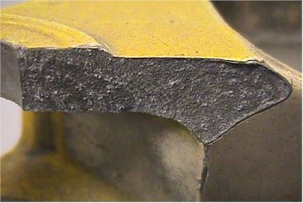
Many of these mechanisms cannot be verified easily by experimental methods. It is suspected that there is no universal model for SCC growth and initiation. Each specific combination of metal environment and stress can produce different fracture evidence. In general SCC fracture surfaces look brittle in nature with evidence of non continual crack growth. Unfortunately, cross sections of samples show some evidence of local ductility or plastic flow as well. this tends to ad to the confusion surrounding mechanistic studies of the process.
Planar slip occurs in stainless steels which fail in SCC by a transgranular mechanism. These alloys are also low stacking fault energy alloys. The intersection of slip bands with passive films is thought to grow cracks.In addition, preferential dissolution in high chloride contents occurs along slip bands. therefore transgranular crack propagation is favored. However, for the sensitized stainless steel, the grain boundaries are favored and intergranular SCC cracks were found.
Measurement of SCC.
Modern measurement of SCC is based on fracture mechanics principles to produce a value of K1SCC. the plain strain fracture toughness under stress corrosion cracking conditions. Fig 1 shows how the value of plane strain fracture toughness under stress corrosion cracking conditions is established. The curve has three distinct regions.

Region 1
A vertical region in which the crack has initiated and grows very rapidly then decreases in crack growth rate. This is where the K1scc determination is made. It is the stress intensity at which a crack will initiate for the metal and environment under test.
Region 2
In region 2 a steady state rate of crack growth is present. The crack is increasing in length and does so over a reasonable range of stress intensity before entering region 3.This is a region of stable crack growth.
Region 3
In this region the fracture toughness of the material is reached and the crack is now unstable as its crack growth rate increases very rapidly with increasing stress concentration to failure.
To obtain the data shown in the figure above, pre-cracked samples are used. A typical four point bend sample is shown in the figure below. In this case the material has a notch in it. Prior to stress corrosion testing a crack is grown from the notch by fatigue. When the crack has reached the desired length the sample is ready for stress corrosion testing.

The stress intensity can be calculated from standard elastic fracture mechanics approach such as:
K= s f(Y) (pa)1/2
where:- K- stress intensity; s - stress applied:f(Y) - geometric factor
a- crack length.
If the load conditions are known and the crack length is measured during the test for a fixed sample geometry, K can be calculated for the stress and crack length. The crack length against K data can then be plotted as above to determine K1scc for individual metals.
Several methods of stress application are available. The test described above is a Rising Step Load Test. The load on the samples immersed in solution is increased at regular time periods of between one and four hours. When the load decreases more than 10% then a crack is assumed to have initiated. At this point the load to initiate a crack is known along with the crack length when the crack started to grow. K1scc can then be calculated.
Alternatively, a single cantilever test can be run. In this case a similar sample is loaded at one end. The load is a constant static load. After a given time period, often 1000hrs, the crack is measured to see if it has grown. Several samples at different loads must be run concurrently. K1scc is determined as the minimum load at which crack growth occurs. Again the crack length is the pre-cracked length.
Many other tests are available, such as C ring test and residual strength tests. In these a C shaped sample is loaded and cracks initiation measured. In a residual strength test, a sample is loaded to 75% of the UTS and left in the environment for 30 days. The sample is then fractured and the fracture stress compared to an unexposed sample. The decrease in failure load is a measure of the SCC susceptibility of the metal. Another similar test is the slow strain rate test. A cylindrical sample in an environment is pulled in a tensile test at very slow strain rates. The low strain rate enables the environment to initiate SCC damage. The decrease in mechanical properties between exposed and unexposed samples at the same strain rate is again a measure of the SCC susceptibility. A double cantilever bend test can also be used. The figure below shows the typical sample.
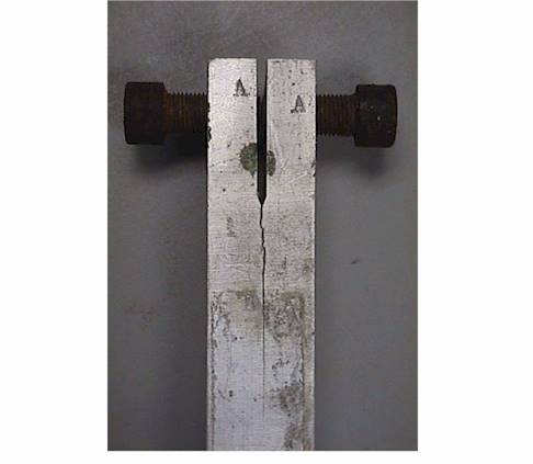
The dimensions are 1 in by 1in by 4 in long. The two bolts threaded into the top are tightened against each other and the material cracked in air. As the crack runs down the sample, the deflection required at the top is met and so the crack then stops running. This then is a measure of K1c for the material. The cracked sample is then placed in the environment of interest and the crack monitored to see if it grows and to what length. After the crack stops growing, the value of K1scc is measured. The value of this is that a single sample provides the measurement of stress corrosion cracking on a quantitative scale.
Effect of Materials Processing on SCC.
It was determined by many researchers that the processing of a material has a significant effect on the stress corrosion resistance of a material. The figure below shows the nomenclature for indicating the orientation of material with respect to processing parameters.
The grain structure after rolling plate or sheet is shown on the figure. The directions indicted as L,S and T are related to the rolling process used to manufacture plate or sheet. The L or longitudinal direction is parallel to the rolling direction. The transverse direction is normal to the longitudinal direction as is the short direction. The T direction is the width of the material while the short direction is the material thickness. For sample orientations the following scheme is used. The first letter indicates the direction which is 90o to the plane of the crack and the second letter indicates the direction of crack growth. The plane shaded would be a crack of the type ST. A sample cut as shown would crack in the ST orientation. This orientation is often the one with the lowest stress corrosion cracking resistance when the intergranular mechanism of SCC is operating. The reason for this is that the ST orientation allows the crack the shortest path through the material completely along grain boundaries with no requirement to propagate transgranularly.

Environments Producing SCC
Aluminum alloys - chlorides, seawater.
Austentitic stainless steels - neutral halides, hot halides, concentrated caustics above 120C.
Ferritic stainless steels - Ammonium nitrates and chlorides, hypochlorites.
Carbon ferritic steels - caustic NaOH solutions greater than 50C, calcium, ammonium and sodium nitrate solutions, seawater.
Nickel chrome alloys - chlorides above 200C, low pH (4) with oxidizers.
Monels - HF acids
Cu-Zn (brasses) - ammonia vapors and salts.
Titanium alloys - organic solvents, methanol.
Prevention
1. Remove or reduce stress - stress relief anneal, thicker sections.
2. Change environment - add inhibitors.
3. Change material - look at data to find better material.
4. Cathodic protection will avoid the problems but remember that hydrogen embrittlement is initiated by cathodic conditions.
CORROSION FATIGUE
Corrosion fatigue is the conjoint action of a cyclic stress and a corrosive environment to decrease the number of cycles to failure in comparison to the life when no corrosion is present. The basic role of the corrosive environment is to decrease the life of the component. Fig 1 indicates the typical data seen for fatigue of ferrous and non ferrous materials. It is a stress against the log of the number of cycles to failure curve, also called an S - N curve. For ferrous materials a distinctive knee is found. For the non ferrous materials and austentitic steels, no knee is found on the curve. When a corrosive environment is present, then the lives to failure often decrease. For the ferrous material, the curve shape is changed as the knee disappears and no distinct threshold stress range exists below which there is no failure.
Features of Fatigue Failure.
Fatigue is a surface initiated process in that the fatigue cracks usually initiate on the exposed surface of a smooth sample. The crack initiation time may be from 25 to 50% of the number of cycles to failure. The initiation stage is called stage 1 in the fatigue process. It is usually accompanied by plastic 
deformation at 45o to the applied stress axis as shown in figure 2. These are called permanent slip bands. The crack length in stage 1 fatigue is usually very small.
At the end of stage 1, the crack macroscopically propagates at 90o to the stress axis in stage 11 of the process. At this point multiple slip processes are occurring which lead to blunting of the crack tip and the formation of striations on the fracture surface. The striations are at 90o to the crack growth directions and look like waves on the ocean surface in form. The striations represent one burst of crack growth but may take more than one cycle to form. Striations are characteristic of the fatigue process. The time form initiation until the last cycle is taken up by crack growth in stage 11 of fatigue, so it may take from 75 to 50% of the fatigue life.
Stage 111 follows stage 11 and operates when the remaining cross section of material is too small to withstand the applied stress and tensile shear overload failure occurs forming a final shear lip at 45o to the surface. The shear lip size depends on the strength of the material and the range of the applied stress. The features on the surface in stage 111 consists of tensile shear dimples.


Corrosion Fatigue.
The effect of a corrosive environment in addition to the cyclic stressing will be felt in stage 1 and 11 of the fatigue process.
Effects on Stage 1 Processes.
In the absence of a corrosive environment the localized plastic deformation in the form of persistent slip bands (PSB's) will initiate cracks. The role of a corrosive environment is to reduce the crack initiation stage by inducing alternative initiation mechanisms. These will include :-
a. local galvanic activity between phases.
b. dissolution of metal after mechanical disruption of passive films by PSB's.
c. metal dissolution simply due to active sites in PSB's.
d. dissolution of grain boundary regions due to compositional effects, for example sensitized steels.
e. pitting corrosion.
These all have a time component which translates into a frequency dependence in fatigue. Therefore it should be noted that corrosion fatigue is a frequency dependent phenomena. Usually, the lower the frequency of the cyclic stressing, the more effective the corrosive environment is in decreasing the fatigue life. These mechanisms either increase the effectiveness of PSB's in initiating cracks or change the initiation mechanism completely, for example pits on the surface of a stainless steel can initiate fatigue cracks.
Effects on Stage 11 fatigue.
The effects on stage 11 fatigue can be separated out by using pre-cracked samples to conduct test. In this case the data can be plotted as the crack propagation rate per cycle against the log of the stress intensity range. These curves are termed da/dn against K or fatigue crack propagation curves.
The methods for determination of fatigue crack propagation curves are similar to those shown for stress corrosion cracking, with the exception that a cyclic load is used. In this case a stress intensity range or K can be calculated from the stress intensity equations if the stress range, crack length and sample geometry are either measured or known. As the crack length must be measured during the test to determine K, then the crack propagation rate per cycle can also be determined by measuring the slope of the crack length against number of cycles data. A typical fatigue crack propagation curve is shown in figure 3.
The usual effect of a corrosive environment is to produce a faster crack propagation rate as indicated in figure 3. The mechanisms associated with this increase in propagation rate are complex and varied.
Mechanisms for Stage 11 Crack Propagation Increase.
Many mechanisms are available to either increase the crack growth rate by accelerating normal crack growth or by invoking modified mechanisms of crack growth.
Corrosion fatigue cracks are usually of the transgranular type although a few exceptions do exist. The general role of the corrosive environment at the crack tip is to accelerate the crack growth rate as shown in the figures.
One mechanism that may be involved is the general corrosion of the crack tip in extending the crack length at all times in addition to the increase in crack length from the mechanical stressing. The crack tip can then be considered to be extending with an increase in the crack growth rate.
A second process is that the corrosive environment oxidizes the surface of the metal very rapidly when the crack opens up. This removes any possibility of the crack tip rewelding and so will maintain a longer crack than expected under non-oxidizing conditions. This process may also have an additional effect. If the corrosion products behind the crack tip build up sufficiently, then a wedging effect may occur in which the crack is held open longer at the tip as the corrosion products stop complete closure. this will also tend to increase the crack growth rate.
The usual features of fatigue can sometimes be modified by the corrosion fatigue process. The striations become flatter and more cleavage like in some cases, possibly by the film cleavage mechanisms applied to stress corrosion cracking.
Prevention Measures.
1. Choose materials with low fatigue crack propagation rates.
Materials can withstand fatigue by two methods. The first is to resist initiation but have a rapid growth rate. The second is to allow easy crack initiation but have a slow crack growth rate. For corrosion fatigue resistance the second is the the better material as in corrosion fatigue crack initiation is accelerated by pitting etc.
2. Reduce stress by thicker sections, design changes.
3. Induce compressive stresses by shot peening.
4. Inhibitors stop corrosive action.
5 Cathodic protection.
6. Coatings, both organic(paints) and inorganic,( zinc, chrome plates etc).
FRETTING CORROSION.
Fretting corrosion is due to the combined action of an aggressive environment and relative, small amplitude motion between two surfaces, one of which is metallic. A normal stress is present between the two surfaces so a rubbing action is present. A wear scar is usually present during fretting. Good examples are press fit bearings on shafts and discs on a shaft bolted together, lap joints and rivets on airplane wings are other examples. The problems caused by fretting are loss of fit, seizure of the component and initiation of fatigue cracks from the fretting site. The conditions for fretting corrosion are as follows:-
1. A high normal load between the two surfaces.
2. Relative motion between the two surfaces, For fretting this value is around 5m (125 mils) or less so it is small amplitude.
3. An aggressive environment to promote corrosion.
The surfaces on a microscopic scale are rough and consist of features called asperities. These will be the features which will contact, so they are responsible for load transfer and friction.

There are three main mechanisms of fretting.
1. The wear oxidation mechanism.
In this the material wears and produces small particles of heavily worked and fractured material. A schematic diagram is shown below to indicate the mechanism. The asperities under load plastically deform and weld together to form a contact. Further relative motion increases the stress and the friction weld fractures, creating small amounts of debris. In this condition the small particles of metal debris are very active and corrode rapidly to produce oxide. The oxide is very hard. The oxide can stay within the fretting area and produce rapid wear by micromachining of fresh soft metal surface. A second possibility is that the oxide leaves the fretting region and loss of fit results.

2. The oxidation wear mechanism.
This is the opposite of process 1 in that the first stage is oxidation of the surface. In the figure below, the surfaces are all oxidized. The oxide is then removed when contact during fretting is made. The debris in this case is hard oxide particles. The exposed metal surface rapidly reoxidizes and the process continues. The hard particles either wear the surface more if contained in the contact region or escape.
Some of the drawbacks of these mechanisms is that the debris was usually plate shaped and did not correlate well with the weld dimensions. The surfaces also showed evidence of plate removal not weld fracture. The delamination theory of wear was proposed to account for these discrepancies.

3. The Delamination Theory of Wear.
In this theory, small platelets of material are detached from the surface of the material. This occurs because the highest stresses are developed inside the material some 10 to 20 m below the surface. This initiates subsurface cracks which run parallel to the surface initially, but eventually come to the surface when the friction between the two surfaces overcomes the stress at the thin neck of the plate. At this stage a thin plate is lifted from the surface. The presence of the aggressive environment acts to accelerate the process by aiding crack growth and again oxidizing the active metal surfaces.
In the figure, the plastic contact zones are shown shaded. The voids initiate below the plastic zone, usually at second phases in the alloy. With further fretting exposure, the voids grow parallel to the surface and eventually connect to the surface when the friction between the plate and the opposing surface is greater than the fracture stress for the small neck of material connecting the plate to the surface. The fresh surface exposed is highly active and cracks exist for solution to penetrate into. Today the delamination theory is widely accepted to control fretting.
Medical implants are thought to be subject to fretting due to the small amplitude of motion between the screwhead and fracture plates. The problem in this case is that metal ions not usually released are released into the body during fretting. If the body is sensitive to them then a rejection reaction will occur and remedial action must be taken. Today Ti-6Al-4V is the metal of choice for implants. It has excellent corrosion resistance in the body which is roughly 5% NaCl solution.
Fretting can influence other processes such as fatigue. Indeed the primary mechanism for the relative motion between the two surfaces can be the cyclic stresses on a metal stretching one region more than another. An example would be a rivet in an airplane wing where the wing is stretched but the rivet is not. The surface damage induced by fretting can then initiate cracks and decrease the fatigue life. This process is then termed fretting fatigue to indicate its role in crack initiation.
Prevention of Fretting.
1. Reduce the normal load.
2. Lubricate to stop the friction between the two surfaces - sometimes called anti fretting compounds.
3. Increase the hardness of the metal by solution hardening.
4. Generally materials that oxidize easily and form tenacious oxides are problems. These include aluminum and its alloys and titanium.
5. Increase amplitude of motion.
6.Use gaskets or sealants between parts.
Testing For Fretting and Fretting Fatigue.
The majority of testing in this case is for fretting fatigue. One test technique is to clamp pads of metal onto a sample being cyclically stressed. The clamped region is immersed in solution. The stressed sample stretches in a tension tension or other cycle and the pads do not change dimension except for the small elastic expansion caused by stress transferring across the interface. A measure of the fretting influence is the decrease in fatigue life compared to the life with no fretting action
Source: http://www.che.uri.edu/course/CHE534w/Chap%208.doc
Web site to visit: http://www.che.uri.edu/
Author of the text: indicated on the source document of the above text
If you are the author of the text above and you not agree to share your knowledge for teaching, research, scholarship (for fair use as indicated in the United States copyrigh low) please send us an e-mail and we will remove your text quickly. Fair use is a limitation and exception to the exclusive right granted by copyright law to the author of a creative work. In United States copyright law, fair use is a doctrine that permits limited use of copyrighted material without acquiring permission from the rights holders. Examples of fair use include commentary, search engines, criticism, news reporting, research, teaching, library archiving and scholarship. It provides for the legal, unlicensed citation or incorporation of copyrighted material in another author's work under a four-factor balancing test. (source: http://en.wikipedia.org/wiki/Fair_use)
The information of medicine and health contained in the site are of a general nature and purpose which is purely informative and for this reason may not replace in any case, the council of a doctor or a qualified entity legally to the profession.
The texts are the property of their respective authors and we thank them for giving us the opportunity to share for free to students, teachers and users of the Web their texts will used only for illustrative educational and scientific purposes only.
All the information in our site are given for nonprofit educational purposes