The mains 400 / 230V supply is derived from a substation transformer. The transformer secondary windings are connected in star as shown in figure 1. The star point provides a neutral for the system. The star point is earthed by the Supply Authority.
Figure 1 illustrates a typical three-phase four-wire distribution system.
Note: The star point and neutral of the transformer secondary winding is earthed.
Typical Three-phase Four Wire Distribution System |
|
Figure 1
This is the voltage of each phase conductor with respect to the neutral conductor. It is illustrated in Figure 1. The value of each phase voltage is 230 Volts AC ( RMS ).
This is the voltage between any two lines ( e.g. between L1 and L2, L1 and L3, L2 and L3 ). It is illustrated in Figure 1. The value of each line voltage is 400 Volts AC ( RMS ).
A 3-phase 400 Volt four-wire supply is used for industrial and commercial loads. Industrial loads usually demand more power than domestic loads and more power can be supplied by a 400V three-phase supply than is possible with a 230V single-phase supply.
It is possible to take the following supplies from a 3-phase 400 Volt four-wire system.
( correctly referred to as a 1-Phase 400 Volt supply ).
Figure 2.
In order to standardise cable colours in all CENELEC countries, the coding has undergone two major changes since 1990. In any system installed before that year it is possible to encounter the old colour codes, which were:
L1 - Red L2 - Yellow L3 - Blue N - Black E - Green
A change was made and it resulted in the following possible situation among others:
L1 - Brown L2 - Red L3 - Yellow N - Blue E - Green / Yellow
Another change was made in 2006 and it resulted in the following colours:
L1 - Brown L2 - Black L3 - Grey N - Blue E - Green / Yellow
Please note from a safety point of view that, old installations will have Black and Blue cores which may be either Phase or Neutral.
When connecting single-phase loads to a three-phase supply, care should be taken to distribute the single-phase loads equally between the three-phases so that each phase carries approximately the same current and the neutral current is kept as low as possible.
Distributing the single-phase loads equally across the three-phases is known as “balancing” the load. A lighting load of eighteen luminaries would be balanced if six luminaries were connected between each of the three-phases and neutral.
Typical layouts of small to medium, industrial installations are shown in Figures 3 and 4.
Figure 3 shows a main supply intake point in a small industrial installation. The main supply is taken through an isolator to a bus-bar chamber. From this chamber, other sub main isolators control the supply to various other sections of the premises. Isolator number 4 is shown supplying a three-phase distribution board, which in turn feeds final circuits.
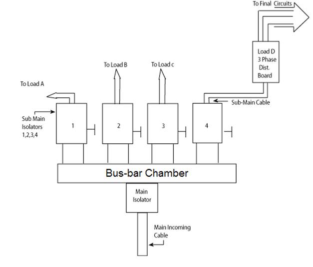
Figure 3.
Figure 4 shows a partially exposed main supply intake point in a small industrial installation. The main supply is taken through a 300 Amp Fused Switch to a bus-bar chamber. This chamber consists of suitably sized copper bars, isolated from each other and from earth. These bars may be of circular or rectangular cross section.
This layout shows the Lighting, Power and Heating loads separated from each other as is often the case. The heating load can be seen to be supplied from the bus-bar, through a 100 Amp Switch Fuse, to a 10 Way Three-phase Distribution Board. This board may be used to supply 10 three-phase loads or a mixture of three-phase loads and single-phase loads. For example it may supply 8 three-phase loads and 6 single-phase loads.
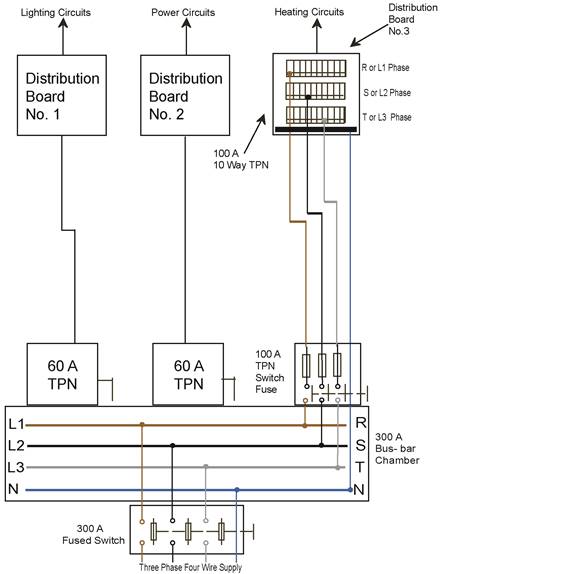
Figure 4.
For correct phase rotation ( polarity ), connect L1, L2, L3 either left to right or top to bottom as appropriate.
Figure 5 shows the internal connections of a distribution board consisting of 3 three-phase MCB’s and 3 three-phase RCBO’s. It may be used to supply 6 balanced three-phase loads, 3 of which require RCD protection.
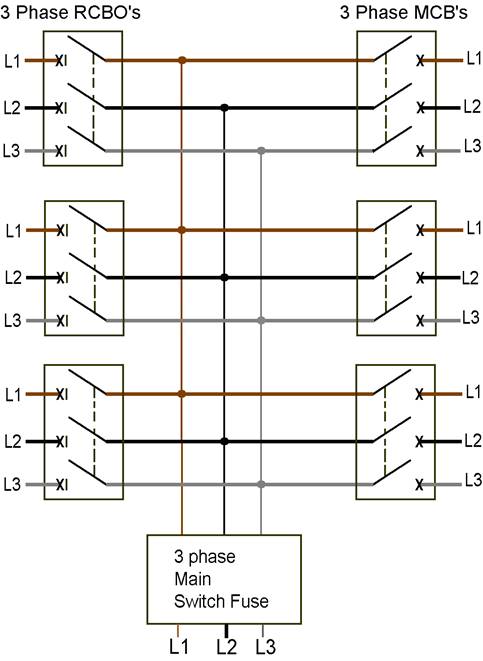
Figure 5.
Figure 6 shows a small industrial distribution board. It is being used to supply a mixture of single-phase and three-phase circuits.
It is supplying a single-phase lighting circuit and a single-phase motor circuit, both of which are not provided with RCD protection. It is also supplying two single-phase socket circuits, which are provided with RCD protection.
It is supplying a three-phase motor circuit, which is not provided with RCD protection. It is also supplying a three-phase socket circuit, which is provided with RCD protection.
It is supplied with three neutral bars. It is of the utmost importance that the various circuit neutrals are not mixed up in any way. A wrong neutral connection will result in the tripping of one or other RCD.
It is possible to supply the single-phase loads through a three-phase RCD. This would simplify the arrangement a good deal, however it is not recommended to supply a mixture of single and three-phase loads through one RCD. The reasons for this are beyond the scope of Phase 2 of the apprenticeship.
The neutral connection for any load not protected by an RCD must be from the main neutral bar.
The neutral connection for any load protected by the single-phase RCD must be from the single-phase RCD neutral bar.
The neutral connection for any load protected by the three-phase RCD must be from the three-phase RCD neutral bar.
Note: There is only one circuit supplied through the three-phase RCD. The neutral connection for this circuit can be taken directly from the three-phase RCD, if a separate neutral bar is not provided.
Small Industrial Distribution Board
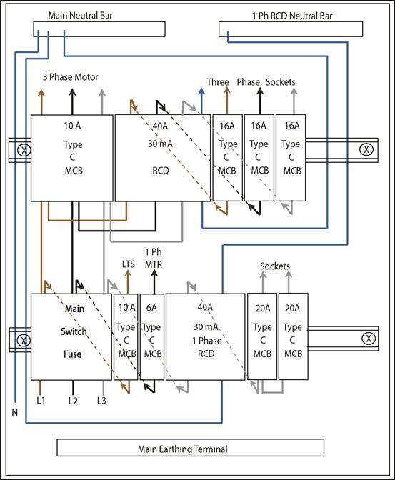
Figure 6.
High Breaking Capacity ( HBC ) fuses are suitable for industrial installations and motor starting circuits. They can distinguish between a starting surge and a short circuit. Their operating characteristics are such that they can disconnect short circuits much more rapidly than any other protective device. For example the HBC fuse can clear a high fault current in 0.01 seconds, while the mechanism of a circuit breaker could take 0.1 seconds to operate.
This type of fuse is also known as a High-Rupturing-Capacity ( HRC ) fuse. Its fuse element is enclosed in a robust cartridge of heatproof material. The cartridge is packed with chemically treated silica sand to quench the arc which occurs as the fuse element ruptures. This ensures that there is no fire risk. They do not deteriorate with age.
The construction of a typical HBC fuse is shown in Figure 7.
|
The barrel of the HBC fuse is made from high grade ceramic to withstand the mechanical forces of heavy current interruption.
The end caps ( tags ) are plated thus ensuring good electrical contact.
The fuse element is accurately shaped and machined to give precise characteristics.
Most HBC fuses are fitted with indicator beads, which show when it has ruptured.
The characteristic of the type C MCB is such that it provides protection of cables supplying loads with relatively high switching surges e.g. electric motors and discharge lamps.
Overload protection is provided by a thermal tripping device.
Short circuit protection and high value over-current protection is provided by a magnetic tripping device.
Type C characteristic stipulates that the MCB must trip magnetically between 5 and 10 times the rated current of the MCB, and it must trip thermally between 1.13 and 1.45 times its rated current.
Short Circuit Protection and high value over-current protection ( Magnetic )
20 x 5 = 100 Amps
20 x 10 = 200 Amps
From this example it can be seen that a Type C must operate between 100 and 200 Amps instantaneously.
Overload Protection ( Thermal )
20 x 1.13 = 22.6 Amps
20 x 1.45 = 29 Amps
From this example it can be seen that a Type C must operate between 22.6 and 29 Amps after a time delay.
Type C – MCB’s are available in different current ratings and breaking capacities to suit a particular installation.
The most common plug and socket arrangement for general-purpose use indoor is the 13Amp Metal Clad type. It is robust and will provide individual protection for the connection of various portable appliances.
Plugs and sockets for industrial and similar purposes are standardized internationally in the CENELEC member countries according to EN 60309. With respect to onerous environments and outdoors, IP ratings are specified.
They are available in 3, 4 and 5 pin versions, with ratings of 16 Amp, 32 Amp, 63 Amp and 125 Amp. They are also colour coded to allow easy identification of one voltage rating from another. The following three basic voltage ratings are covered in Phase 2.
Voltage Colour Code General Use
110 Volt Yellow Power Tools
230 Volt Blue 1-Phase Loads
400 Volt Red 3-Phase Loads
This is a very simplistic view as there are several other factors involved, such as frequency and current rating. The more common varieties used in Ireland are as follows:
![]() Appliance Inlets, Couplers, Plugs and Sockets 100-130V ~ 2 Pole + Earth
Appliance Inlets, Couplers, Plugs and Sockets 100-130V ~ 2 Pole + Earth
![]() Appliance Inlets, Couplers, Plugs and Sockets 200-250V ~ 2 Pole + Earth
Appliance Inlets, Couplers, Plugs and Sockets 200-250V ~ 2 Pole + Earth
![]() Appliance Inlets, Couplers, Plugs and Sockets 380-415V ~ 2 Pole + Earth
Appliance Inlets, Couplers, Plugs and Sockets 380-415V ~ 2 Pole + Earth
![]() Appliance Inlets, Couplers, Plugs and Sockets 380-415V ~ 3 Pole + Earth
Appliance Inlets, Couplers, Plugs and Sockets 380-415V ~ 3 Pole + Earth
![]() Appliance Inlets, Couplers, Plugs and Sockets 380-415V ~ 3 Pole + Neutral + Earth
Appliance Inlets, Couplers, Plugs and Sockets 380-415V ~ 3 Pole + Neutral + Earth
The EN 60309 standard has made today’s electrical plugs and sockets extremely safe and reliable. Reliability is mainly due to the use of pin-and sleeve connections made of solid brass. The sleeves are equipped with stainless steel springs to ensure constant contact pressure. A further safety feature is the fact that plugs and sockets of differing frequency, voltage or current ratings are not interchangeable. Wherever a plug is used, it will only fit the matching socket. This is achieved firstly by means of a keyway on the socket and a matching key on the plug. In addition to this the earth pin and sleeve positions provide further interlocking.
The twelve, clock positions are used to locate the earth pin and sleeve positions. The keyway of the socket is always at the 6 O’clock position. The earth pin and sleeve are larger diameter and also longer than the other pins and sleeves. This means that the earth is connected first and disconnected last.
The 110 Volt socket earth sleeve is located at the 4 O’clock position.
The 230 Volt socket earth sleeve is located at the 6 O’clock position.
The 400 Volt socket earth sleeve is located at the 6 O’clock position.
By referring to the chart below, it can be seen that different supplies, voltages and frequencies are catered for in such a way that safety is ensured. The electrician must of course understand the system.
This is a 16 Amp-110 Volt 2 Pole + Earth plug and surface mounted socket. Note the position of the earth pin in the plug. It is in the 8 O’clock position, but remember this will match up with the earth sleeve in the socket which is in the 4 O’clock position.
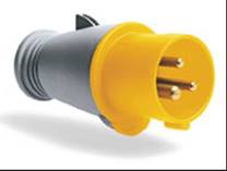

Figure 8
This is a 16 Amp-230 Volt 2 Pole + Earth plug and surface mounted socket. Note the position of the earth pin in the plug. It is in the 6 O’clock position and will match up with the earth sleeve in the socket which is also in the 6 O’clock position.
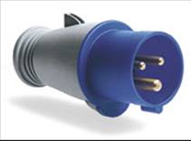
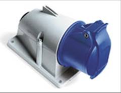
Figure 9
This is a 16 Amp- 400 Volt 3 Pole + Earth plug and surface mounted socket. The earth pin in the plug and earth sleeve in the socket are both in the 6 O’clock position.
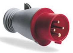
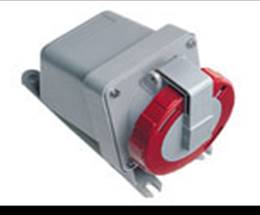
Figure 10
This is a 16 Amp- 400 Volt 3 Pole + Neutral + Earth plug and surface mounted interlocked switched socket. For safety reasons the plug cannot be inserted or withdrawn when the switch is in the on position. Again the earth pin in the plug and earth sleeve in the socket are both in the 6 O’clock position.
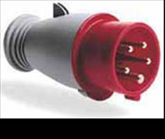
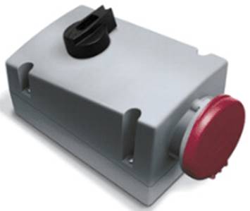
Figure 11
This is a 16 Amp- 110 Volt and a 230 Volt 2 Pole + Earth coupler or trailing socket. These are used on the end of extension leads. They are also used to connect supply to appliances via an appliance inlet. The earth sleeve positions here will be the same as the matching sockets.


Figure 12
This is a 16 Amp- 400 Volt 3 Pole + Earth and a 400 Volt 3 Pole + Neutral + Earth coupler or trailing socket. These are used on the end of extension leads. They are also used to connect supply to appliances via an appliance inlet. The earth sleeve positions here will be the same as the matching sockets.
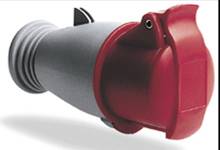

Figure 13
This is a 16 Amp- 110 Volt and a 230 Volt 2 Pole + Earth surface mounted appliance inlet. These are used to connect power to transportable machines etc. where a flexible cord is undesirable. The earth pin positions here will be the same as the matching plugs.

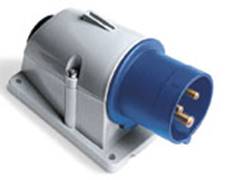
Figure 14
This is a 16 Amp- 400 Volt 3 Pole + Earth and a 400 Volt 3 Pole + Neutral + Earth, surface mounted appliance inlet. These are used to connect power to transportable machines etc. where a flexible cord is undesirable. The earth pin positions here will be the same as the matching plugs.
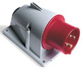
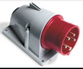
Figure 15
.
Industrial Socket Circuits
EN 60309 socket circuits in industrial premises may also be wired in radial or ring format. In either case the load on the circuit must be assessed and the cables and protective device(s) must be capable of supplying this load. Each socket should be individually protected against overcurrent. The cables used must have a current carrying capacity equal to or greater than the rating of the overcurrent protective device.
For example:
2.5mm2 conductors 20 Amp MCB
Circuits supplying socket outlets must be protected by an RCD with a rated tripping current of 30 mA. There are some exemptions specified in the ETCI rules.
Rated Tripping Current I![]() N ( e.g. 30mA )
N ( e.g. 30mA )
Contact Rated Current IN ( e.g. 40A )
Source: http://local.ecollege.ie/Content/APPRENTICE/liu/electrical_notes/LL232.doc
Web site to visit: http://local.ecollege.ie
Author of the text: indicated on the source document of the above text
If you are the author of the text above and you not agree to share your knowledge for teaching, research, scholarship (for fair use as indicated in the United States copyrigh low) please send us an e-mail and we will remove your text quickly. Fair use is a limitation and exception to the exclusive right granted by copyright law to the author of a creative work. In United States copyright law, fair use is a doctrine that permits limited use of copyrighted material without acquiring permission from the rights holders. Examples of fair use include commentary, search engines, criticism, news reporting, research, teaching, library archiving and scholarship. It provides for the legal, unlicensed citation or incorporation of copyrighted material in another author's work under a four-factor balancing test. (source: http://en.wikipedia.org/wiki/Fair_use)
The information of medicine and health contained in the site are of a general nature and purpose which is purely informative and for this reason may not replace in any case, the council of a doctor or a qualified entity legally to the profession.
The texts are the property of their respective authors and we thank them for giving us the opportunity to share for free to students, teachers and users of the Web their texts will used only for illustrative educational and scientific purposes only.
All the information in our site are given for nonprofit educational purposes