
Introduction to Tungsten Arc Gas Shielded (TAGS) Welding
Welding of aluminium and magnesium had always been a problem with conventional manual metal arc and oxyacetylene processes. Corrosive fluxes had to be used to remove the oxide film from the material surface and molten pool.
To overcome this problem, and to eliminate atmospheric contamination during welding, inert gas was first employed as a shield in the early 1930s.
The first gas-shielded process used a tungsten electrode and helium shielding gas. It was called the tungsten inert gas (TIG) process. Direct current with electrode positive was used. With this system, the tungsten electrode tended to overheat and transfer fragments of tungsten to the weld unless a low current was utilised.
It was found that overheating could be avoided by making the tungsten electrode negative. This made the process suitable for welding stainless steel but unsuitable for aluminium and magnesium.
The development that allowed these materials to be welded was the use of alternating current, with a high-frequency, high-voltage current superimposed over the basic welding current to stabilise the arc. Using a.c. gives the perfect answer for welding aluminium and magnesium. When the electrode is positive, a cleaning action takes place on the surface of the weld and plate area; particles of oxide are lifted up electrically, leaving an oxide-free area. On the next half-cycle, the electrode becomes negative, allowing it to cool slightly and preventing overheating. As the cycle repeats, the alternating current gives the perfect balance of oxide removal and electrode cooling; the inert gas shield prevents further contamination until the molten pool has solidified.
The process can be called TIG (tungsten inert gas) or TAGS (tungsten arc gas-shielded) welding. In these notes TAGS is used, as the term also covers the use of gas shields that may not be strictly inert.
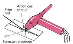
TAGS welding uses an inert (non-reactive) gas shield, usually argon or helium, to surround a non-consumable tungsten electrode, thus protecting the electrode and molten pool area from the atmosphere. This means that welding can be carried out without the need for a chemical flux.
The welding heat is created by an electric arc formed between the end of the tungsten electrode and the work. Tungsten is used as the electrode because it has a very high melting point (about 3400°C).
Basic Principle of Tungsten Arc Gas-Shielded Welding
Tungsten arc gas shielded welding is usually called TAGS welding. It uses an arc between a tungsten electrode and the work to fuse the joint. The electrode is not melted and any filler metal needed to build up the weld profile is added separately.
Both the molten metal in the weld pool, the tip of the filler wire and the hot electrode are protected from atmospheric contamination by a shield of inert gas. Usually the gas is argon, but helium by itself or mixed with argon may be used for special applications. Argon - hydrogen mixtures can be used for stainless steel.
TAGS welding is suitable for both manual and automatic welding.
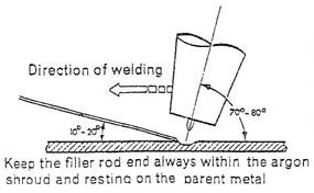
In manual welding, the operator points the electrode in the direction of welding and uses the arc to melt the metal at the joint.
If filler metal is required, for example when making a fillet weld, it is added to the leading edge of the weld pool.
Filler is supplied as cut lengths of wire - usually 1 metre long.
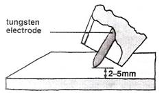
Arc length is controlled by the welder and is usually between 2mm and 5mm.
Heat input to the arc depends on the current chosen by the operator.
Travel speed is adjusted to match the time needed to melt the joint.
Arc Length - Controls Weld Width
When TAGS welding was first developed, the simplest way to start the arc was to touch the tungsten electrode to the workpiece. This caused the current to begin to flow. The electrode was then simply raised until the required arc length was obtained for the particular welding application.
This method was called touch or scratch starting. Instead of striking the arc directly on to the workpiece and risking electrode contamination, a carbon block was used. The carbon block was placed near the start of the weld. Once the arc was established on the block, it could be moved down the side of the block to the workpiece.
The development of special high frequency arc-starting circuits eliminated the need for touch starting and has reduced the problem of tungsten contamination in welds.
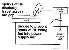
High Frequency unit is used to start the arc without touching
With the onset of electronic controls it is now possible to control and adjust the current levels during the TAGS welding process. The pulsing of both the levels of current and the time duration allow for greater control of the heat input into the weld pool which minimises distortion of the base metal.
Tungsten arc gas shielded welding has the following advantages:
TAGS is one of the cleanest, most precise welding procedures available. The operator has complete control over all welding variables and can change most during the welding process with no need to stop the weld. TAGS does have a few disadvantages,
Power sources for use with TAGS welding must be capable of delivering a constant current at a preset value. They are often called 'drooping characteristic' units.
Rectifier units are commonly used for dc welding although motor generators may be more suitable for site work.
Single phase transformer units are almost universally used for welding aluminium. Modern power sources have square waveform.
Combined ac/dc power sources can be used where there is a mix of work.
Modern power sources combine constant current and constant voltage (cc/cv) and are called inverters.
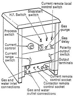
The power source should be equipped with:
There are 2 types of TAGS welding plant which are classified in accordance with their output current; direct current (DC) and alternating current (AC). Sizes vary from 3 to 400 amperes output.
Direct current with the electrode connected to the negative terminal of the power source is used for:
Alternating current is used for welding:
Usually single-phase transformers, either air or oil cooled.
The built-in auxiliaries usually include:
Usually three-phased rectifier units comprising:
In many cases a switch is provided to enable the power source to be used for manual metal-arc welding with D.C.
Single-phase transformer rectifiers can provide either an A.C. or D.C. output as required.
These power sources usually include automatic high-frequency sources for both A.C. and D.C. welding, together with the usual auxiliaries.
(In many cases a switch is provided to enable the power source to be used for manual metal-arc welding with A.C. or D.C.).
Note: Power sources used for manual metal-arc welding can be adapted for this process if additional features are added to the circuit.
It is better to use a composite power source specially designed for tungsten-arc gas shielded welding, that can be switched subsequently for use in manual metal-arc welding.
There are many designs available, but they all fall into two main categories.
The lighter air-cooled torches are made for welding thinner sheet sections. They are usually in three sizes - up to 50 amps capacity, 75 amps capacity or 100 amps capacity - but these ratings can vary with different makes.
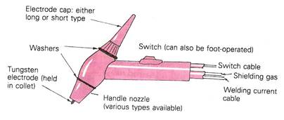
A Typical Air-Cooled Torch
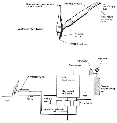
Water-cooled torches are designed for more heavy-duty welding of thicknesses up to approximately 12 mm. They can have current capacities from 100 to 500 amps. They usually incorporate a fuse system to cut off the current supply and to save damage to the equipment should there be a water supply failure.
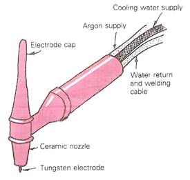
A Typical Water-Cooled Torch
A foot or hand control unit (on the torch) can be used for gradually reducing the current towards the end of a weld run. This allows the build-up and elimination of the end crater while maintaining the protection of the argon gas shield.
Ceramic nozzles are used with both the air and water-cooled torches up to about 200 amps. However, above this amperage, metal nozzles with water cooling should be used.
Various shapes and sizes of nozzle are available to suit all ranges of work. These include shorter nozzles for working in confined spaces, transparent nozzles for improved visibility, and extended nozzles for welding in deep recesses.
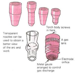
Various Types of Nozzle
Gas nozzles are not particularly strong and the effect of constantly being heated and then cooled can make them brittle. You should therefore handle them with care in order to obtain maximum usage.
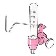
Gas flow meter and economiser
Some equipment contains automatic flow controls for both shielding gas and water cooling. They can operate in conjunction with the contactor and allow argon to flow for a preset duration before and after welding.
Argon and helium are the two most commonly used shielding gases used for GTAW. The characteristics most desirable for shielding purposes are the chemical inertness of the gases and their ability to produce smooth arc action at high currents. Both gases are inert, causing an ionization effect in the welding arc. They protect the tungsten electrode and the molten weld pool from the atmosphere.
Gas purity affects a weld. Metals will withstand small amounts of impurities, but, for the best results, the percent of inert gas used should be at least 99.9 percent pure.
Argon is heavier than helium and may be supplied in liquid or gaseous form. Argon provides for good cleaning action. The flow rates are determined by the size of the tungsten and the gas cup diameter. Argon is suitable for welding similar and dissimilar metals and works well while welding in the vertical and overhead welding positions.
Helium is a lighter inert gas. It can be distributed as a liquid, but is used more often as a compressed gas. It leaves the weld area faster than argon, and higher flow rates are necessary when using it.
Helium produces a narrow but deep heat-affected zone (HAZ), which is good for welding on heavier metals. It is suitable for welding at high speeds and gives good coverage in vertical and overhead welding positions. It helps to increase the penetration, and when used as a back purge, it tends to flatten the pass of the weld bead. Helium is suitable for use on thicker nonferrous metals.
Argon and helium mixtures are used when welders need the control of the argon and the penetration of the helium. This mixture is not necessary when welding plain carbon steels.
Typical mixtures vary, depending on the application. It is often used for automatic welding applications.
Argon and hydrogen mixtures are often used for welding of stainless steel. This mixture should not be used when welding plain carbon steels. The typical mixture is 95 percent argon and 5 percent hydrogen.
Nitrogen can also be used as a shielding gas, but is rarely used because of its higher current requirements. It is suitable for welding copper.
Welding-grade argon is supplied in steel cylinders painted light blue. The usual size of cylinder is 8.5 m³ charged at a pressure of 172 bar (2500 lbf/m²). Take care that the cylinder pressure does not fall too low, as the moisture level of the gas can rise as the cylinder pressure falls.
Use light gloves when T.A.G.S. welding to avoid burning through radiation and H.F. burns between the fingers.
We need some reference text here, which module and unit should they refer to?
Pure tungsten electrodes were originally used for TIG welding, however to improve the quality of tungsten electrodes, certain additions can be made during manufacture. The main elements added are either zirconium or thorium. These help to reduce tungsten inclusions in the weld, which increases the current-carrying capacity and the life of the electrode while also giving improved arc stability.
Thoriated and zirconiated types give easier starting and better arc stability and are generally preferred.
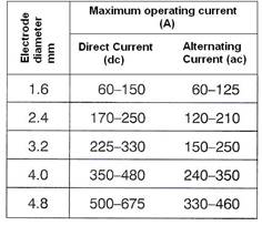
Electrode diameters for TAGS Welding
Before use, the end of the electrode is ground on a silicon carbide wheel to give the most appropriate profile. Contamination with other metals must be avoided as this lowers the melting point of the electrode. The illustration below shows approximate dimensions. Always use localised dust extraction when grinding tungstens.
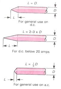
Preparation of Tungsten Electrodes (Approximate Dimensions)
For dc welding a sharp point is required. For ac welding only a small bevel is needed as the end of the electrode becomes rounded when the arc is operated.
When welding thinner materials, edge joints, and flange, filler metals are not used. For thicker materials, an externally fed filler wire is generally used. The type of filler metal wire to be used is based on the chemical analysis of the base metal. The size of the filler metal wire depends on the thickness of the base metal, which usually dictates the welding current. Filler material can be added manually when needed from the side, right in the weld puddle, by alternatively introducing the wire tip into the arc and withdrawing it.
For optimal corrosion performance of some stainless steel, TAGS welding with filler, that is more highly alloyed with nickel relative to the base metal is a more reliable and effective method of maintaining the desired austenite-ferrite balance in the weld metal with mechanical properties and corrosion resistance equivalent to those of the base metal. Filler wire with a 7.0 to 9.0% nickel as compared to the 5.5% nickel typically in the base metal can be used.
The following are generic instructions for the setting up of a Tungsten-Arc Gas Shielded Welding plant. As there are many different suppliers of TAGS welding equipment is not possible to provide a specific check list.
Equipment, particularly composite power sources, vary considerably in their control arrangements and therefore it is important to verify that actual equipment used is set-up correctly.
Always
Tungsten Arc Gas Shielded Welding plant set-up
Cleaning the material to be welded is important. TAGS welds are often susceptible to contamination during welding. The surface to be welded must be free from oil, grease, paint, dirt, oxides, and other foreign material.
Aluminum has an oxide coating that, if not removed, will contaminate the weld area. Cleaning solutions, wire brushes, grinders, and abrasive blasting are some of the methods used to remove these contaminants.
Weld jigs and positioning will also affect the shape, size, and uniformity of a weld. Fixtures hold the material to be welded in place while controlling distortion, helping to locate and maintain parts in their position relative to the weld.
When weld jigs are employed, they can reduce the time for welding. Positioning will help move the weld into a flat position to improve productivity for the welder.
Chill blocks, heat sinks, or backing bars may also be used when welding some metals to prevent burn-through, reduce base material temperatures, or to minimize distortion.
Material |
16 s.w.g. (1.5 mm) stainless steel, 1 off, min. 4˝ (10.0 cm) x 6˝ (15.0 cm). |
Preparation |
Clean surface. |
Assembly |
Support sheet in flat position, long axis, and parallel to bench front. |
Electrode |
1/16˝ (1.5 mm) |
Argon |
5-8 ft.³/hr. |
Current |
50-70 amperes |
Filler |
1/16˝ (1.5 mm) |
Material |
16 s.w.g. (1.5 mm) aluminium, 1 off, min. 4˝ (10.0 cm) x 8˝ (20.0 cm). |
Preparation |
Surface cleaned immediately before welding. |
Assembly |
as for EP 43. |
Electrode |
3/32˝ (2.5 mm) |
Argon |
8-12 ft.³/hr. |
Current |
50-75 amperes |
Filler |
3/32˝ (2.5 mm) |
Examine deposited beads and note any variations in width or height of run or depth of fusion into parent metal. These may be caused by variations in arc length, rate of travel, rate of addition of filler metal. Assess causes and take appropriate corrective action.
The reverse side of the sheet should indicate traces of penetration without any burn-through.
Title |
Author |
Ref. Code |
The Induction Book, “Code of Behaviour & Health & Safety Guidelines” |
SOLAS |
|
Basic Welding and Fabrication |
W Kenyon |
ISBN 0-582-00536-L |
Fundamentals of Fabrication and Welding Engineering |
FJM Smith |
ISBN 0-582-09799-1 |
Workshop processes, practices and materials, 3rd edition, Elsevier Science & Technology |
Black, Bruce J 2004 |
ISBN-13: 9780750660730 |
New Engineering Technology |
Lawrence Smyth & Liam Hennessy |
ISBN 086 1674480 |
|
|
|
Source: http://local.ecollege.ie/Content/APPRENTICE/liu/pipefitting/word/M2_U5_Tungsten%20Active%20Gas%20Shielded%20Welding.doc
Web site to visit: http://local.ecollege.ie
Author of the text: indicated on the source document of the above text
If you are the author of the text above and you not agree to share your knowledge for teaching, research, scholarship (for fair use as indicated in the United States copyrigh low) please send us an e-mail and we will remove your text quickly. Fair use is a limitation and exception to the exclusive right granted by copyright law to the author of a creative work. In United States copyright law, fair use is a doctrine that permits limited use of copyrighted material without acquiring permission from the rights holders. Examples of fair use include commentary, search engines, criticism, news reporting, research, teaching, library archiving and scholarship. It provides for the legal, unlicensed citation or incorporation of copyrighted material in another author's work under a four-factor balancing test. (source: http://en.wikipedia.org/wiki/Fair_use)
The information of medicine and health contained in the site are of a general nature and purpose which is purely informative and for this reason may not replace in any case, the council of a doctor or a qualified entity legally to the profession.
The texts are the property of their respective authors and we thank them for giving us the opportunity to share for free to students, teachers and users of the Web their texts will used only for illustrative educational and scientific purposes only.
All the information in our site are given for nonprofit educational purposes