XI. TURBOMACHINERY
This chapter considers the theory and performance characteristics of the mechanical devices associated with the fluid circulation.
General Classification:
Turbomachine - A device which adds or extracts energy from a fluid.
Adds energy: Pump
Extracts energy: Turbine
In this context, a pump is a generic classification that includes any device that adds energy to a fluid, e.g. fans, blowers, compressors.
We can classify pumps by operating concept:
1. Positive displacement
2. Dynamic (momentum change)
General Performance Characteristics
Positive Displacement Pumps
1. Delivers pulsating or periodic flow (cavity opens, fluid enters, cavity closes, decreasing volume forces fluid out exit opening).
2. Not sensitive to wide viscosity changes.
3. Delivers a moderate flow rate.
4. Produces a high pressure rise.
5. Small range of flow rate operation (fixed pump speed).
Dynamic Pumps
1. Typically higher flow rates than PDs.
2. Comparatively steady discharge.
3. Moderate to low pressure rise.
4. Large range of flow rate operation.
5. Very sensitive to fluid viscosity.
Typical Performance Curves (at fixed impeller speed)
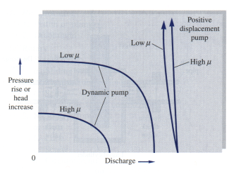
Fig. 11.2 Performance curves for dynamic and positive displacement pumps
Centrifugal Pumps
This is the most common turbomachine used in industry. It includes the general categories of (a) liquid pumps, (b) fans, (c) blowers, etc.
They are momentum change devices and thus fall within the dynamic classification.
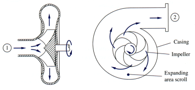
Fig. 11.3 Cutaway schematic of a typical centrifugal pump
Writing the energy equation across the device and solving for hp – hf ,we have
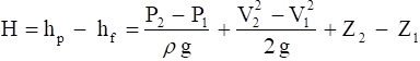
where H is the net useful head delivered to the fluid, the head that results in pressure, velocity, and static elevation change.
Since for most pumps (not all), V1 = V2 and DZ is small, we can write
|
Since friction losses have already been subtracted, this is the ideal head delivered to the fluid. Note that velocity head has been neglected and can be significant at large flow rates where pressure head is small. |
The ideal power to the fluid is given by |
Pw = r Q g H |
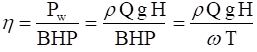
The pump efficiency is given by |
|
where BHP = shaft power necessary to drive the pump
w = angular speed of shaft
T = torque delivered to pump shaft
Note that from the efficiency equation, pump efficiency is zero at zero flow
rate Q and at zero pump head, H.
Basic Pump Theory
Development of basic pump theory begins with application of the integral conservation equation for moment-of-momentum previously presented in Ch. III.
Applying this equation to a centrifugal pump with one inlet, one exit, and uniform properties at each inlet and exit, we obtain
![]()
where ![]() is the shaft torque needed to drive the pump
is the shaft torque needed to drive the pump
![]() are the absolute velocities at the inlet and exit of the pump
are the absolute velocities at the inlet and exit of the pump
Thus, the applied torque is equal to the change of angular momentum across the device.
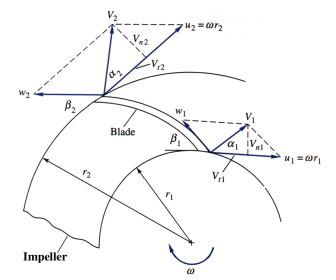
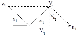
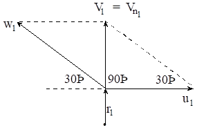
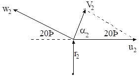
Fig. 11.4 Inlet and exit velocity diagrams for an idealized
pump impeller
Since the velocity diagram is key to the analysis of the device, we will discuss the elements of the diagram in detail.
1. At the inner radius r1 we have two velocity components:
a. the circumferential velocity due to the impeller rotation b. relative flow velocity tangent to the blade These combine to yield the absolute inlet velocity V1 at angle a1 |
|
The absolute velocity can be resolved into two absolute velocity components:
1. Normal ( radial ) component:
|
Note that for ideal pump design, |
2. Absolute tangential velocity:
|
again, ideally |
It is also important to note that ![]() is used to determine the inlet flow rate, i.e.,
is used to determine the inlet flow rate, i.e.,
![]()
where b1 is the inlet blade width.
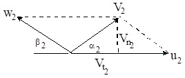
Likewise for the outer radius r2 we have the following:
a. the circumferential velocity due to the impeller rotation b. relative flow velocity tangent to the blade These again combine to yield the absolute outlet velocity V2 at angle a2 |
|
The exit absolute velocity can also be resolved into two absolute velocity components:
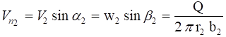
1. Normal ( radial ) component:
|
Note that Q is the same as for the inlet flow rate |
2. Absolute tangential velocity:
![]()
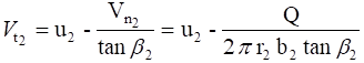
where ![]()
Again, each of the above expressions follows easily from the velocity diagram, and the student should draw and use the diagram with each pump theory problem.
We can now apply the moment - of – momentum equation.
![]() (again Vt1 is zero for the ideal design)
(again Vt1 is zero for the ideal design)
For a sign convention, we have assumed that Vt1 and Vt2 are positive in the direction of impeller rotation.
The “ ideal” power supplied to the fluid is given by
![]()
or
![]()
Since these are ideal values, the shaft power required to drive a non-ideal pump is given by

The head delivered to the fluid is
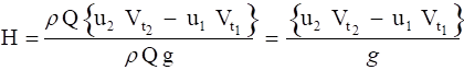
For the special case of purely radial inlet flow
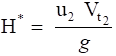
From the exit velocity diagram, substituting for Vt2 we can show that
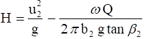 has the form C1 - C2 Q
where: C1 = |
C1=shutoff head, the head produced at zero flow, Q = 0 |
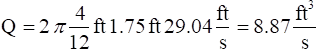
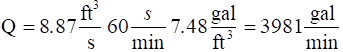
Example 11.1:
A centrifugal water pump operates at the following conditions:
speed = 1440 rpm, r1 = 4 in, r2 = 7 in, b1 = 30o, b2 = 20o, b1 = b2 = 1.75 in
Assuming the inlet flow enters normal to the impeller (zero absolute tangential velocity):
find: (a) Q, (b) T, (c) Wp, (d) hp, (e) DP
![]()
Calculate blade tip velocities:
|
|
Since the design is ideal, at the inlet |
|
This is the flow rate for ideal design or Vt1 = 0 and a1 = 90˚.
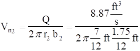
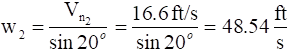
Repeat for the outlet:
|
|
![]()
We are now able to determine the pump performance parameters. Since for the centrifugal pump, the moment arm r1 at the inlet is zero, the momentum equation becomes

This is the ideal torque delivered to the fluid.
Ideal power delivered to the fluid:
![]()
Note that for a real (non-ideal) pump the input power (motor size) required would be greater proportional to the efficiency of the pump.
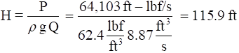
Head produced by the pump (ideal):
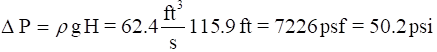
Pressure increase produced by the pump:
Source: http://www.eng.auburn.edu/~tplacek/courses/2610/samba/CHEN2610FacultyCh11a.doc
Web site to visit: http://www.eng.auburn.edu
Author of the text: indicated on the source document of the above text
If you are the author of the text above and you not agree to share your knowledge for teaching, research, scholarship (for fair use as indicated in the United States copyrigh low) please send us an e-mail and we will remove your text quickly. Fair use is a limitation and exception to the exclusive right granted by copyright law to the author of a creative work. In United States copyright law, fair use is a doctrine that permits limited use of copyrighted material without acquiring permission from the rights holders. Examples of fair use include commentary, search engines, criticism, news reporting, research, teaching, library archiving and scholarship. It provides for the legal, unlicensed citation or incorporation of copyrighted material in another author's work under a four-factor balancing test. (source: http://en.wikipedia.org/wiki/Fair_use)
The information of medicine and health contained in the site are of a general nature and purpose which is purely informative and for this reason may not replace in any case, the council of a doctor or a qualified entity legally to the profession.
The texts are the property of their respective authors and we thank them for giving us the opportunity to share for free to students, teachers and users of the Web their texts will used only for illustrative educational and scientific purposes only.
All the information in our site are given for nonprofit educational purposes