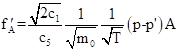
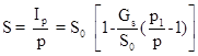
In reality a hole leading to an ideal vacuum does not exist. Real vacuum pumps arrive to some ultimate limit pressure where their pumping speed goes to zero. Let us consider in the place of an ideal vacuum a hole connecting to a volume with the pressure p`. The number of gas particles colliding with the hole per unit time (f'A):
 (1)
(1)
The above formula contains a forward stream and a backward gas stream. Writing (1) in a different way we get:
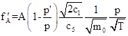 (2)
(2)
The factor ![]() characterizes the pump efficiency.
characterizes the pump efficiency.
For an optimally designed pump one requires the maximum A and the minimum p`.
Vacuum pumps are characterized by the pumping speed S, [m3/h] or [l/s], (1 m3/h = 0.28 l/s) and by the ultimate pressure p¥. Observe that S=S(p) – pump characteristics. S~A, p¥. depends on the total back-stream and the materials used to build and lubricate the pump.
Insert example of pump S(p) characteristics mech.-Roots-diff.
Zoology of vacuum pumps
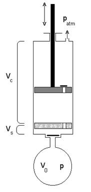
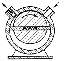
Old designs were in the form of a piston pump. Modern design – a rotary pump. In a single cycle of the pump operation the number of particles in the pumped volume will be reduced by: where Vc is the volume of the pump cylinder, Vo is the pumped volume. All volume pumps have a dead volume Vs which determines the ultimate pressure: The amount of gas in the dead volume Qs=pVs=760 Vs
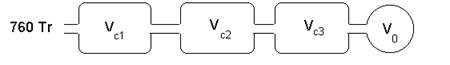
To improve p¥ one should increase the pumping volume and decrease the dead volume. The best way is to reduces the back pressure well below 760 Tr e.g., by multistage pumping. |
Multistage pumping.=: An example – the three stage pump:
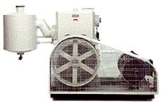
 The most commonly used pumps for all basic vacuum applications from atmospheric pressure down to 10-3 Torr. They are used as backing pumps for other high-vacuum gas transfer pumps such as turbo-molecular and diffusion pumps.
Principle of operation:
Gas enters the inlet port and is trapped between the rotor vanes and the pump body. The eccentrically mounted rotor compresses the gas and sweeps it toward the discharge port. When gas pressure exceeds atmospheric pressure, the exhaust valve opens and gas is expelled. Oil is used as lubricant and sealant.
The geometrical speed of pumping Sg=V N, where V is the volume between the rotor and the stator and N is the speed of rotation. The geometrical speed is limited by the conductivity of the pump inlet and inside channels.

The main contribution to![]() is the size of holes leading to the cylinder (limited by the slide width). p¥ is determined by the design, quality of machining and oil vapour pressure.
is the size of holes leading to the cylinder (limited by the slide width). p¥ is determined by the design, quality of machining and oil vapour pressure.
Typically:
 one stage 10-1 - 10-3 [Tr]
 Cooling -forced air or water.
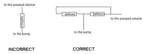
Venting - necessary in the old types to prevent the back flow of oil.
 2.1.2. Dry pumps
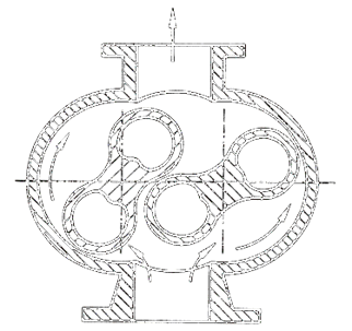
The rotary lobe pump (Roots) is excellent for moving large quantities of gas at higher pressure than possible with the rotary oil or piston pumps. Roots pumps are in use in molecular beam experiment and IC fabrication lines that need high pumping speed at 0.1 to 10 Tr.
The lobes are similar to the figure eight in cross section (see Fig 2d). They mash with each other and counter-rotate to continuously transfer gas from one side of the pump to the other. The compression ratio of the pump is small and varies with the molecular weight of the gas. Light gases easily escape back into the vacuum vessel around the edges of the rotors, creating a beck stream, so rotary or piston pumps must back roots pumps. Typically pump speed: N»1500-3000 rpm, gap between the rotors: 1-0.15 mm.
Geometrical pumping speed S0 (![]() ) creates the forward stream
) creates the forward stream
![]()
The backward stream is constituted by gas flow through a clearance between the stator and rotor surfaces. If Gs is the clearance conductivity then:
![]()
The effective pumping:
![]()
Pumping speed at the pump inlet:
To maximize the speed, maximize ![]() -( high N, low leaks high volume).
-( high N, low leaks high volume).
 when
when ![]()
Typically ![]() »10-2 Þ Roots pumps needs backing pump.
»10-2 Þ Roots pumps needs backing pump.
Roots pump characteristics –Insert Fig. 2e
Problems:
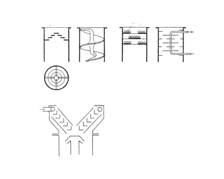
Principle of operation: Insert Figs:
![]()
![]()
![]() is a coefficient,
is a coefficient, ![]() chamber height,
chamber height, ![]() chamber length, v linear speed of the rotor.
chamber length, v linear speed of the rotor.
To increase ![]() a spiral rotor is used (Fig: 3b).
a spiral rotor is used (Fig: 3b). ![]() »10-6[Tr.], S»100[l/s], (pback » 10-3)
»10-6[Tr.], S»100[l/s], (pback » 10-3)
Maglev pumps p~10-9 Tr, S~10l.s @ 10-7 Tr
The drag pump has a smooth, high-speed rotor, shaped like an inverted bowl, that spins between two closely spaced, cylindrical walls. The walls have helical grooves facing the rotor. The rotor reaches a tangential velocity that approaches the average velocity of gas molecules. The pumping action is induced by momentum transfer from the rotor to the gas molecules in the direction of the exhaust port. The spiral grooves are designed to assist gas flow in the right direction
A molecular drag pump may reach a compression ratio of 109 for N2, 104 for He, and 103 for H2, while discharging into a fore-line pressure of 10 to 40 Torr.
These pumps accept continues inlet pressure below 0.1 Torr and are used where low pumping speed (less than 10 L/s) and modest ultimate pressure (no lower than 10-6 Torr) are demanded.
The hybrid pump combines several stages of turbo pumps with drag pumps. The result is a pump with a higher pumping speed that backs into a high fore-line pressure.
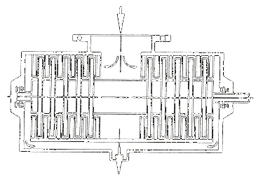
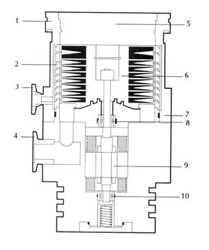
Turbomolecular pumps known also as “turbo pumps”; their 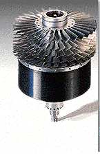 application cover all processes and vacuum system in the 10-4 - 10-10 Tr. pressure range. Turbo pump resembles a jet engine. Several very high-speed rotor, each with multiple blade shaped with angled leading edges, impart momentum to gas molecule in the direction of the next rotor down the stack. The compression ratio across the pump for a meditate molecular weight gas may exceed 108.
Turbo pumps have advantages over diffusion pumps. Correctly operated they do not back-stream oil into the vacuum system at any time and can be started and stopped in a few minuets. The last feature means a turbo pump can be directly connected to the chamber without a high vacuum valve. This saves money and improves pumping conductance. But turbo pump can be noisy and they induce vibration. The turbo pumps are also expensive and the compression ratio for hydrogen and helium are low.
 Insert figures 3 (c-e)
![]() ~5 10-11 Tr, N~105 rpm, S~10000 l/s
~5 10-11 Tr, N~105 rpm, S~10000 l/s
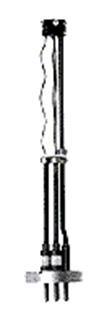
1 – High vacuum connection flange.
2 – Stator pack.
3 – Venting connection flange.
4 – For-vacuum connection flange.
5 – Splinter guard.
6 – Rotor.
7 – Pump casing.
8 – Bearing.
9 – Motor.
10 – Bearing.
![]() »10-4[Tr]
»10-4[Tr]
S » up to15000 [l/s]
Oil volume 5[l]
Heating power » 5kW
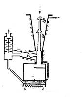
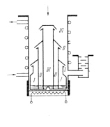
2.2.3. Diffusion pumps
There are numerous applications for diffusion pumps, ranging from high gas volume found in molecular beam investigation and large-scale vacuum furnace processing to ultra-high vacuum level needed for surface physics research and space simulation chambers. These pumps operate from 10-4 Tr. to5*10-11 Tr. The latter pressure range is not easily obtained with a diffusion pump and requires an exceptionally good LN2 trap and additional pumping from a Titanium sublimation pump.
Diffusion pumps operate by boiling a fluid, often hydrocarbon oil, and angling the dense vapour stream in a downward conical direction back into the pump boiler. Gas molecules from the system that enter the oil curtain are pushed toward the boiler by momentum transfer from the large fluid molecules.
Oil traps are designed so that there will be no optical connection between the pump and the vacuum chamber, in that way it is possible to reduce the back-stream of oil vapour with no influence on the conductivity. Fig 4a-b.
Diffusion pumps Principle of operation see Fig: 4.
Vapour disk – clean surface for gas particles
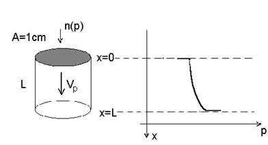
I+=kvpn(x)
I--=D dn(x)/dx
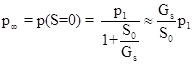
Ipump=I+ - I-- ; ![]() =p(S=0); kvpn(x)= D dn(x)/dx
=p(S=0); kvpn(x)= D dn(x)/dx
![]()
The limiting pressure is lower when vapour speed and pumping length is higher and D is smaller. D decreases with increasing vapour density, molecular mass of vapour particles and molecular mass of gas particles.
Typically: ![]()
The advantages of the diffusion pumps are:
The disadvantages are associated with pumping fluid
Multistage and fractioning diffusion pumps
General characteristics:
![]() »10-6[Tr.]-10-8[Tr.] s » 2 [l/s] -104 [l/s] Oil volume = 20cm3 - 500 cm3
»10-6[Tr.]-10-8[Tr.] s » 2 [l/s] -104 [l/s] Oil volume = 20cm3 - 500 cm3
Operation procedures must protect boiling oil against oxidation during pump-vent cycles.
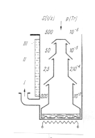
I=Sp(inlet)=Sp(stage III)= Sp (stage II) = Sp(stage I)
Since p<pIII<pII<pI, therefore SIII>SII>SI
Oil traps
 High vacuum optical traps
Apiezons : A - natural hydrocarbons p(25 C) ~ 10-5
B - destileted hydrocarbons p(25 C) ~ 10-7
C - destileted hydrocarbons p(25 C) ~ 10-8
Silicon: Dc703 - phenylmethyl dimethyl cycioxane [(CH3)3SiO] [(CH3)3SiO] [(CH3)3SiO]
Dc704 - tetramethyl tetraphenyl trisiloxane 4 pieces chain
Dc705 - pentaphenyl trimethyl trisiloxane 5 pieces chain
Santovac (Convalex) - synthetic polyphenol ether – space lubricant – expensive!
**See Table: 4a
OPERATING A DIFFUSION PUMP VACUUM SYSTEM
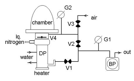
DP – diffusion pump
BP – primary (backing) pump
V1 – backing valve
V2 – bypass valve
V3 - vent (air inlet) valve
V4 – high vacuum valve
G1 – fore-vacuum gauge
G2 – high vacuum gauge
Employed for extending life-time of vacuum radio valves.
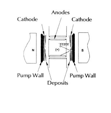
From the time of their commercialisation in the late 1950s (by Varian), ion pumps have been a primary choice for UHV systems. They are clean, bakeable, vibration free, operate in the 10-11 Torr range with low power consumption and have long operating lives. All ion pumps have the same basic components: a parallel array of short stainless steel tubes, two plates (Ti or Ta) spaced a short distance from the open ends of the tubes and a strong magnetic field parallel to the tube axes.
Electrons released from the (cathodic) plates are constrained by the magnetic field into tight helical trajectories in the (anodic) tubes. The potential energy of gas molecules ionised in the tubes is converted to kinetic energy and the cathode sputters titanium when struck by an ion. The sputtered material coats the tubes, the cathode plates and the pump’s walls. Several pumping mechanisms are possible including chemical reaction, ion burial and neutral burial - the last two accounting for the pump’s ability to handle inert gases.
There are three types of ion pumps. The plate material and form, and the voltage supply determine their names and characteristics. In the diode pump, the Ti plates are grounded and the tubes have a high positive voltage. It has high pumping speed for H2, O2, N2, CO2, CO and other getterable gases. The noble diode pump has the same electrical arrangement as the diode but one plate is Ti and the other is Ta. This reduces the pumps H2 pumping speed, but allows higher speed and greater stability for Ar and He. In the triode pump, the plate’s electrodes are slotted and connected to high negative voltage. Both the tubes and the pump casing (acting as a third electrode) are grounded. Sputtering from the slotted plate’s deposits Ti not only on the tubes and other areas of the plates but also on the pump casing. Inert gas burial and active gas reaction on the casing is less susceptible to interference by ion bombardment, even at high system pressures when ion bombardment of the plates is high. The triode pump is the therefore the optimum choice when the system’s pressure will vary throughout the ion pump’s range.
*
* Ion current - measure of vacuum. The pump is simultaneously a vacuum gauge.
* Problems associated with arc discharge and heating due to overloading
Typical design – mixed operation
Ion pump incorporated into a single unit with a Ti sublimation pump
Zeolite: originates from greek Zein (to cool)+ Lithos (stone)
Dehydrated aluminosilicate: e.g., Na2O Al2O3 nSiO2mH2O
Dehydration creates channels with calibrated diameter size, 0.1 nm<D<10 nm, and the network of chambers, of the volume of the order of 1000 A3, interconnected by narrow channels. The effective surface ~ 1000 m2/g! 50% of the zeolite volume is constituted by chambers and channels.
Originally operated as molecular sieve and filters:
NaA-A4 – has channels of D~ 4A: Therefore, the absorption of the elongated O2 molecule (l=3.9 A and D=2.8 A) increases with decreasing temperature, but that of the spherical A molecule (D=3.83A at –150 C) decreases.
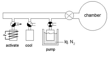
These gas capture pumps are equivalent in function to the rotary oil pump. they are used for rouging vacuum system to a pressure level of 10-1-10-5 Torr where another type of gas capture pump can take over. Cryosorption pumps are used most often as starting devices in ion pumped systems.
They should not be confused with cryogenic pumps that are HV and UHV pumps. Cryosorption pumps are strictly for pumping large volumes of gas from atmospheric pressure. They are essentially tubes sealed at one end (often finned internally to aid heat transfer), and filled with molecular sieve pellets (zeolite) that are cooled by the liquid nitrogen surrounding the pump. The cold molecular sieve can adsorb the air in a system down to a sub-Torr pressure in a few minutes. Cryosorption pumps have a simple blow-off valve this makes their regeneration automatic. Cryosorption pumps do not back-stream they are low cost and, almost problem-free.
These gas capture pumps fill a niche. They are never used as the only type of pump in the UHV system. They are most often used to supplement ion pumps (occasionally diffusion pumps) increasing the pumping speed for reactive gases particularly when poling the system through the 10-5 to 10-8 Torr range to UHV pressures.
Ti sublimation pump operate by depositing a film of titanium (from a filament that is resistant heated) over a surface cooled to LN2 temp’. Active gases (hydrogen, oxygen, and nitrogen) react to form non-volatile compound with the film. Sublimation pumps are switched on intermittently, ether by time/pressure controller or manually when the operator judge the previous film has all reacted.
2.3.5. Getter pumps
In their operational mode getter pumps are similar to Ti sublimation pumps and share the distinction of being secondary rather than primary pumps. However, the name ‘getter’ is often applied to devices attached to a system that will never be opened to atmosphere after initial pump-down. Examples can be found in the electric lamp, CRT and vacuum tube industries. When the system is at its ultimate pressure a very reactive metal (often barium or titanium) is evaporated onto the inner surface of the chamber and reacts with any gas that evolves from the walls throughout the lifetime of the device.
This gas capture pump is particularly useful for systems containing gases other than helium or hydrogen. Cryopumps have rapidly increased in popularity and variety of applications in recent years. Their major use at present is in sputtering systems applied to semiconductors processing, where oil-free operation and a huge capacity for pumping argon process gas are needed. They are particularly suited to pumping high molecular weight gases in the 10-6 to 10-9 Torr range.
The pump has two low temperature zones, an inner surface held at approximately 20K and a surrounding surface at approximately 80K (Helium refrigeration). The inner surface is coated with activated carbon that assists in pumping hydrogen by adsorption. The low temp’ are achieved by attaching the pump directly to a helium cryo-compressor.
The most important feature of the cryopump is the cleanliness of the vacuum. The pumping speed can be vary high and the ultimate vacuum (in the absence of hydrogen and helium) excellent. In contrast with ion pumps, which are also oil free the cryopumps, is mach less susceptible to failure or damage if switched on at high pressure.
Pressure vs temp’ Fig: 6a.
Cryo-coolers Fig: 6b-d
![]()
Recalling the value of c1 , c3 we get:
![]()
Efficiency of cryo-pumping for gas at 300 K and 77 K :
gas |
g |
M0 |
S[cm2l/s] 300K |
S[cm2l/s ] 77K |
H2 |
0.5 |
2 |
22 |
12 |
H2O |
0.9 |
18 |
13 |
7 |
Air |
0.7 |
28-32 |
9 |
5 |
CO2 |
0.8 |
44 |
8 |
4 |
A |
0.7 |
40 |
7 |
4 |
Final pressure for the gas of the temperaqture T at the cryogenic surface of the temperature Ts. pp is a saturated vapour pressure of the gas at 4.2 K

Hydrogen problem: ![]() H2 = 5*10-7Ö300/42 = 4*10-6 [Tr.]
H2 = 5*10-7Ö300/42 = 4*10-6 [Tr.]
cooling of the gas dues not help much: ![]() H2 = 5*10-7Ö77/42 = 2*10-6 [Tr.]
H2 = 5*10-7Ö77/42 = 2*10-6 [Tr.]
N.B. cryopumps very effective for H2O vapour usually difficult for other pumps.
Complex pumping systems have to be designed in such a way that a constant gas flow through entire system will be maintained. This requires:
![]()
Pumping speed should increase towards forevacuum in order to avoid blocking of the cascaded pump.
Source: http://physweb.bgu.ac.il/COURSES/ExperiMethods/lecture_notes/1_2_Vacuum_pumps.doc
Web site to visit: http://physweb.bgu.ac.il/
Author of the text: indicated on the source document of the above text
If you are the author of the text above and you not agree to share your knowledge for teaching, research, scholarship (for fair use as indicated in the United States copyrigh low) please send us an e-mail and we will remove your text quickly. Fair use is a limitation and exception to the exclusive right granted by copyright law to the author of a creative work. In United States copyright law, fair use is a doctrine that permits limited use of copyrighted material without acquiring permission from the rights holders. Examples of fair use include commentary, search engines, criticism, news reporting, research, teaching, library archiving and scholarship. It provides for the legal, unlicensed citation or incorporation of copyrighted material in another author's work under a four-factor balancing test. (source: http://en.wikipedia.org/wiki/Fair_use)
The information of medicine and health contained in the site are of a general nature and purpose which is purely informative and for this reason may not replace in any case, the council of a doctor or a qualified entity legally to the profession.
The texts are the property of their respective authors and we thank them for giving us the opportunity to share for free to students, teachers and users of the Web their texts will used only for illustrative educational and scientific purposes only.
All the information in our site are given for nonprofit educational purposes