
In most fabrication shops wiring is essentially a hand operation. As a general rule the allowance for a wired edge is 2½ times the diameter of the wire. The flange or edge is folded up just over 90° and knocked over the wire with a mallet. A skilled craftsman can control the operation of forming the metal over the wire by pulling over or knocking back the metal with the mallet. Figure 2 illustrates common faults which may occur when wiring a straight edge.
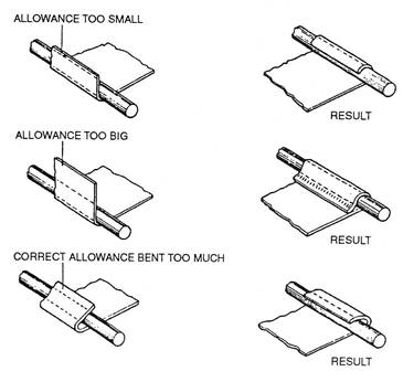
Figure 2 - Typical Faults when Wiring a Straight Edge
The formula for working out the wire allowance is not always accurate enough.
To ensure accuracy cut a strip of metal and apply formula. Check workpiece and establish if more or less metal is needed to make wiring job perfect. Repeat as often as needed. Always make sure you use the same gauge material and process when using the 'trial and error' method.
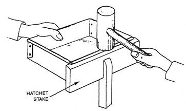
Figure 3 - Hatchet Stake
The head is tapped along the top edge with a mallet and the sharp edge of the hatchet stake ‘tucks’ the edge of the metal to the wire as shown in Figure 4.
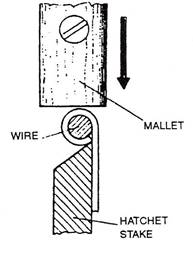
Figure 4 - Tucking the Edge of the Metal to the Wire
The wired edge is placed down in a suitable groove in a crease iron and tightened up by flattening the metal above the wire with a mallet.
The wired edge is moved progressively along the groove during this operation until the whole length is tightened.
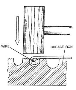
Figure 5 – Flattening the Metal above the Wire with a Mallet
For a wired edge the allowance must be equal to 2½ times the diameter of the wire. The measurement is taken from the face of the gauge to the centre to the lower roll as shown in Figure 6. The gauge is adjusted. After setting to the required measurement the gauge is locked in position.
When flanging a disc, a small piece of metal, folded, should be used to prevent injury to the operator's hand. Remove all burrs from the metal disc before commencing the operation.
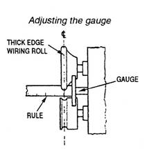
Figure 6 - Edge Preparation on a Jennying Machine
This is mild steel with a coating of tin. Tin melts at 232°C. When fabricating items out of tinplate the joints are usually soft soldered. This renders them water-tight. Care must be taken not to scratch the tin off the tinplate. Tinplate has largely been replaced by stainless steel and aluminium. Solder is a mixture of lead and tin.
Wiring rolls are similar to jenny rolls but the top roll has a wide rounded edge and the lower roll has a radiussed groove. Various widths of top rolls are available for different diameters of wire.
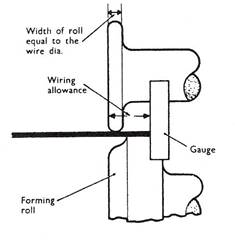
Figure 7 - Wiring Rolls
Select correct top roll. Fit top and bottom rolls. Set gauge to dimension required. Allowing for wire allowance measure from outside of top roll.
Support work between wheels and tighten adjusting screw. Turn handle keeping edge of work in contact with gauge. Raise work while turning as for jennying. Tighten top rolls until required shape is obtained.
Support on suitable stake and insert pre-formed wire.
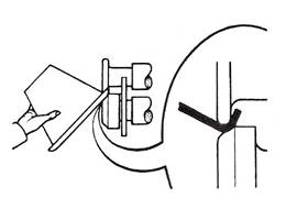
Figure 8 - Insert Pre-formed Wire
Close metal over wire using mallet.
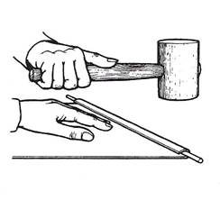
Figure 9 - Close Metal over Wire
Change forming roll for closing rolls. Top closing roll has curved inner edge as shown in Figure 10. Close wired edge as you would form edge in easy stages until metal is tucked in all around.
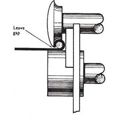
Figure 10 - Closing Roll
Add an allowance of 2½ times the diameter of the wire to any edge requiring a wired finish.
Cylindrical work may be wired before rolling to shape. Mark wiring allowance into three parts.
Bend allowance as shown in Figure 11, using bending or folding machine. Cut wire to required length.
Note: Add thickness of wire to outside diameter of cylinder when calculating length, plus extra for projection past end of work. Make a saw cut through approx. 2/3 of wire diameter at correct length mark.
Place work on bench plate. Position wire so that the uncut end is projecting beyond edge of work, to ensure that wire joint & seam of cylinder do not coincide.
Note: When work to be wired has a grooved joint, wire must project at the end of work with grooving fold turned down.
Close metal over wire with mallet at one end of work. Repeat operations along the wire.
Close metal over remainder of wire.
Select hatched stake and check that it is free from chips or marks. Fit securely in a stake holder or vice.
Position work as shown in Figure 13, sheet against face of hatchet stake.
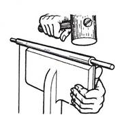
Figure 13 - Position Sheet against Face of Hatchet Stake
Tap along top edge of work to close or "tuck in" edge of metal to wire.
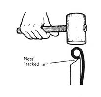
Figure 14 - Tuck in Edge of Metal to Wire
Select and fit a creasing iron after checking that it is free from marks.
Position work, wired edge down into a suitable groove.
Tighten wire by flattening metal above wire with mallet.
Move work along groove, striking directly above iron until whole length is tightened.
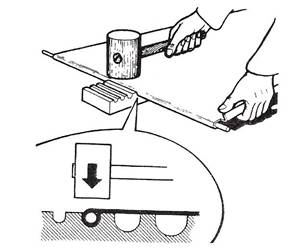
Figure 15 - Select and Fit a Creasing Iron
Set edges of sheet to required curvature on a suitable bar or mandrel, before forming in bending rolls. Fit metal strips in groove folds to prevent accidental closure.
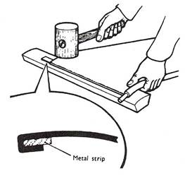
Figure 16 - Set Edges of Sheet to Required Curvature
Position work in bending rolls after selecting suitable size wiring groove.
The slip roll is the one on which cylinder is formed and from which formed cylinder can be removed.
Grip saw cut end of wire with pliers and pull outwards.
Wire will snap off at saw cut, opening folded edge of metal sufficiently to allow projecting wire end to be inserted.
Hook groove and slide edge as shown in Figure 19 until wire projection slides into opened part of wired edge.
Form groove joint and close opened part of wired edge, tucking in to finish.
Flat panels with curved edges, are frequently stiffened by wiring. Conical work may also be wired before forming.
Edges may be prepared for wiring using the jenny machine or Universal Rotary Machine.
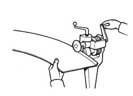
Figure 20 - Preparing Edges for Wiring
Note: Edges may also be prepared by hand, using a half moon stake, or bench mandrel. Ensure edge of stake or mandrel is not too sharp.
Form "break" mark using a mallet. Hold plate at a slight angle during this operation. Observe "break" mark follows marked line.
Reposition plate to approximately 2/3 of allowance.
Form second break.
Repeat operation, at approx 1/3 of allowance.
Cut wire slightly in excess of requirements and form to shape. Place plate on a suitable flat surface and position wire against edge, allowing a slight projection of ¼" - ½" (6 mm - 12 mm).
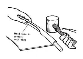
Figure 23 - Position Wire against Edge
Note: If a conical article is being wired before forming, calculate the length of the wire required, saw, cut and position as for wiring cylinders.
Close metal over wire using a mallet.
Strike top edge with mallet to tuck in wire.
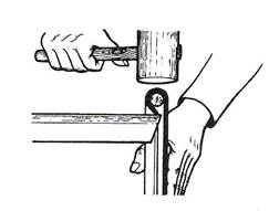
Figure 24 - Strike Top Edge with Mallet
Examine work to determine if material bent over wire is sufficient to completely cover the wire without leaving any gap between edge and surface of wire.
Note: If insufficient material has been bent over wire, strike edge with a drawing motion to bring over more metal.
Failure to do so will mean a gap being left between edge and surface of the sheet.
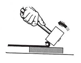
Figure 26 – Insufficient Material Bent over Wire
If excess material has been bent over wire, strike edge with a drawing motion to reduce amount of material available for complete coverage of wire.
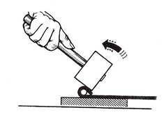
Figure 27 - Excess Material Bent over Wire
An alternative method is to use a jenny or Universal Rotary Machine to tuck in the metal.
When using the machine be careful not to mark the metal.
Flat discs when wired may become loose in the centre due to edge stretching caused by the wiring operation. This may be corrected by reversing the wiring using a jenny or Universal Rotary Machine.
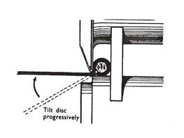
Figure 29 - Wired Discs
External curved wired edges require extreme care being exercised during the edge preparation and wiring operation, to prevent splits developing.
Edge preparation.
Mark off wiring allowance and select a suitable hatchet stake or other straight edge stake.
Place work on stake and with a stretching hammer, form "break" mark. Hold work at a slight angle during this operation.
Repeat striking operations along edge of work until edge is at right angles to work.
Place work on bench with edge overhanging. Support back of edge with a hatchet stake - knock flange back to 45º approx.
Close metal over wire with a mallet, working in stages to close metal evenly.
If work is to be rolled to shape, tucking in may be left until forming is complete.
Use a bossing mallet for small radii.
An alternative method of tucking in is to make use of a paining down hammer.
Exercise care when using the hammer to prevent scratches or marks on surface of plate.
Conical work may be wired flat or after forming to shape.
Use may be made of a marking gauge made from a piece of metal with a notch cut to the required allowance.
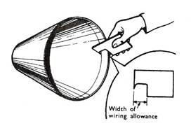
Figure 35 - Marking Gauge
Select a suitable square edge stake with slight radius on edge free from marks etc.
Work in stages, stretching carefully to avoid cracking of edges until flange is square.
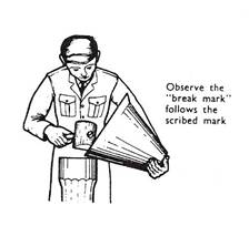
Figure 36 - Observe the "Break Mark"
Calculate length of wire required. Cut to length and form to circular shape.
Support work on a suitable stake mandrel.
Place wire against flange, ensuring that its joint does not coincide with body joint.
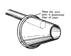
Figure 37 - Length of Wire Required
Close metal over wire at several points on circumference using a mallet. Hold wire against flange with thumb of free hand. Turn work as required to ensure mallet strikes solidly over stake or bar.
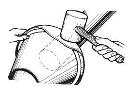
Figure 38 - Close Metal over Wire
Close remainder of flange over wire in stages, turning work as required.
Note direction of blow as flange is worked over.
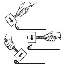
Figure 39 - Close Remainder of Flange over Wire in Stages
Transfer work back to square edge stake and tuck in wire as shown in Figure 40.
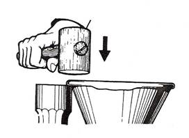
Figure 40 - Square Edge Stake
Replace work on funnel stake and tighten wire as shown in Figure 41.
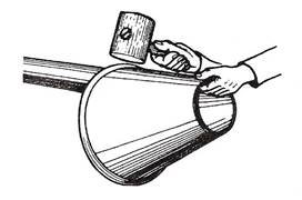
Figure 41 - Funnel Stake
Backlapped wired edges are frequently used as a means of stiffening boxes fitted with lids.
This method of stiffening gives the strength of a wired edge, combined with a smooth straight edge on which to fit the lid.
It is usual when forming edges of this type to use a heavier gauge of wire on the body, thus permitting an equal overall size of body and lid to be maintained.
The usual difference is two gauges of wire.
Hinging arrangements are often included in the backlapping process.
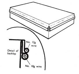
Figure 42 – Stiffening Boxes with Lids
Construction of a box with wired edge lid and backlapped body.
Marking out.
Mark off body pattern including allowances for backlapping.
Mark off on one side, position of hinges. Mark to depth of backlap allowance.
Mark position of bends for sides. Mark off end patterns including allowances for backlapping.
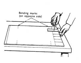
Figure 43 – Box with Wired Edge and Backlapped Body
Note: Make allowances for type of body-end joint used.
(Lap soldered joint will be used in this example).
Cut notches in ends to be depth of backlap allowance.
Support sheet firmly and saw cut slots at hinge marks, cutting slots down to allowance mark.

Figure 44 - Cut Slots to Allowance Mark
Cut wires for body of box. These must be cut to leave ends short of body edges.
Place work on a suitable flat surface and position wire so that it is short of each end equally. Wire edge as previously described, inserting short stubs at ends to prevent closure of metal at ends.
Cut wires to length of box end plus extra to form "tails". Mark wires for bending so that each tail is equal.
Bend tails at right angles and wire ends as previously described.
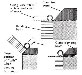
Figure 48 - Forming
Remove wire studs from body wiring, after marking ends to indicate length of box and tails required.
Cut box end tails to correct length.
Fit ends to body pushing tails into space left by wire studs. Align ends and solder in position.
Support box firmly and file top edge of backlap on each hinge position until double thickness is filed off, leaving a hinge tub.
Cut and form lid, wiring edge after forming.
Source: http://local.ecollege.ie/Content/APPRENTICE/liu/sheetmetal_notes/Wiring_M1_U11.doc
Web site to visit: http://local.ecollege.ie
Author of the text: indicated on the source document of the above text
If you are the author of the text above and you not agree to share your knowledge for teaching, research, scholarship (for fair use as indicated in the United States copyrigh low) please send us an e-mail and we will remove your text quickly. Fair use is a limitation and exception to the exclusive right granted by copyright law to the author of a creative work. In United States copyright law, fair use is a doctrine that permits limited use of copyrighted material without acquiring permission from the rights holders. Examples of fair use include commentary, search engines, criticism, news reporting, research, teaching, library archiving and scholarship. It provides for the legal, unlicensed citation or incorporation of copyrighted material in another author's work under a four-factor balancing test. (source: http://en.wikipedia.org/wiki/Fair_use)
The information of medicine and health contained in the site are of a general nature and purpose which is purely informative and for this reason may not replace in any case, the council of a doctor or a qualified entity legally to the profession.
The texts are the property of their respective authors and we thank them for giving us the opportunity to share for free to students, teachers and users of the Web their texts will used only for illustrative educational and scientific purposes only.
All the information in our site are given for nonprofit educational purposes