This section describes the type of working drawings used in engineering. In order to draw and understand engineering drawings, some knowledge of features such as bearings in which spindles rotate, gears for transmitting motion between rotating parts and cams for changing rotation into straight-line motion, is necessary. Basic principles concerned with these features are described, together with examples of and exercises in engineering drawing.
Spindles and shafts in machines run in bearings, of which there are many different types. A few of the more common are shown here. A steel spindle can run in a hole in cast iron without any special type of bearing and this simple bearing requires lubricating from time to time with lubricating oil. The steel spindle is usually case hardened - a thin skin of the spindle has extra carbon added by heat treatment and is then hardened. Although spindles running directly in holes in cast iron are reasonably satisfactory, a better bearing is formed when a bush is inserted between the spindle and cast iron, as indicated in Figure 1. The bush is made of materials such as phosphor bronze or an alloy known as white metal. Such bushes can be replaced when they become worn after constant use.
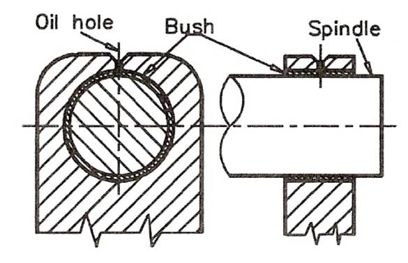
Figure 1 - Bush and its Lubricating Hole
One of the more common forms of bearings are those incorporating steel balls or rollers. Figure 2 shows the general symbol for drawing any form of ball or roller bearing. Figure 3 is a two-view orthographic projection of a roller bearing, both views being in section.
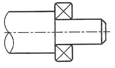
Figure 2 - Standard Drawing Symbol for a Ball or Roller Bearing
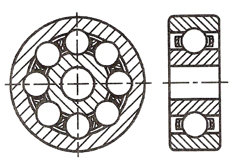
Figure 3 - Sectional Views through a Roller Bearing - a Journal
Figure 4 shows two sectional views, the first through a roller bearing. The second section is a view through a needle bearing - needles being rollers of very small diameter.
All ball and roller bearings consist of:
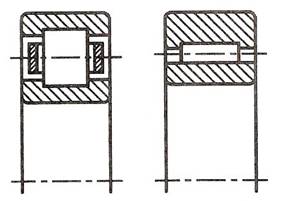
Figure 4 - Sections Through a Roller Bearing and a Needle Bearing – Journals
There are three groups of ball and roller bearings:
Figure 5 is a sectional view through a thrust bearing in which the roller elements are tapered rollers. Thrust bearings will take much heavier loads than journal bearings.
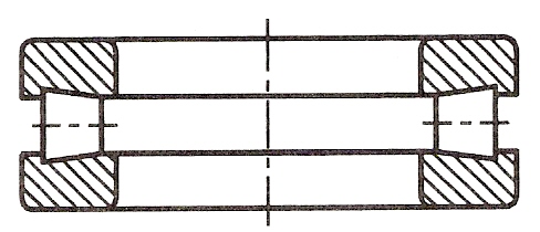
Figure 5 - Thrust Bearing with Taper Rollers
For transferring rotation from one spindle (or shaft) to another, spur gears are commonly used. A spur gear is a circular disc with a central hole, usually with a keyway cut in it for fixing to a spindle via a key. The gear has a number of gear teeth cut around its circumference. The profile of gear teeth in the majority of spur gears is based on the involute to a circle. Some gears often those used in watches and clocks) are based on the cycloid to a circle.
The standard symbol for drawing spur gears in technical drawings is shown in Figure 6.
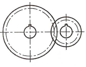
Figure 6 - Standard Symbol for Two Meshing Spur Gears
Note: that the base circle centre lines for each gear (on which the involute is based) meet tangentially.
Figure 7 shows a number of gear teeth taken from two meshing spur gears. It is most unlikely that you will be required to draw such gear teeth. Figure 7 shows the appearance of meshing involute gear teeth. In technical drawings use the symbols for spur gears, not the actual outlines of the gear teeth.
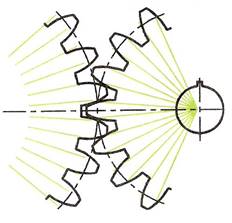
Figure 7 - Enlarged View of Involute Gear Teeth from Two Meshing Gears
Figure 8 is a Front view of a two-gear gear train. The rotation of either gear brings about a rotation in an opposite direction in the gear with which it is meshed. Thus the clockwise rotation of the left hand gear is translated into an anticlockwise rotation in the right hand gear.
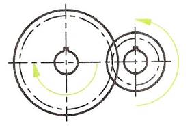
Figure 8 - Two Spur Gears in a Train
Note the change in direction of rotation.
Figure 9 is another gear train, in which the rotation of the uppermost gear is repeated in the bottom gear using what is known as an idler gear.
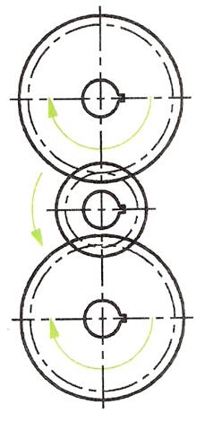
Figure 9 - Gear Train of Three Spur Gears, the Middle One is an Idler Gear
Bevel gears are suitable for changing the angular direction of rotation through gear trains. Figure 10 is a two-view orthographic projection showing the standard technical drawing method of drawing a bevel gear. The gears shown in Figure 10 are for changing the angle of rotation through 90 degrees, but bevel gears are made for changing the angular rotation through any angle.
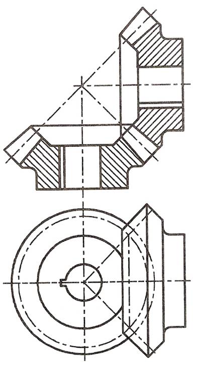
Figure 10 - Pair of Bevel Gears Drawn using Standard Technical Drawing Methods
Radial cams, diagrammatic examples of which are given in Figure 11 to Figure 14 are for converting radial motion into straight-line motion. As a radial cam rotates, the follower running on its surface moves up and down according to the outline of the radial profile of the cam.
All cams are designed for the purpose of converting one form of motion into another.
Radial cams can have different types of follower.
In Figure 11 wedge-shaped and roller followers are shown. In Figure 12 flat and off-line followers are shown.
Figure 13 shows a cam associated with a rocker arm for transferring the rotation of the cam into an up and down vertical movement. Figure 14 shows one of the most commonly used cams in modern machinery - the cam system designed to operate the valves in an internal combustion engine driven by petrol.

Figure 11 - Rotary Cams - Wedge Shaped and Roller Followers
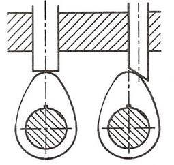
Figure 12 - Rotary Cams - Flat and Off-Line Followers
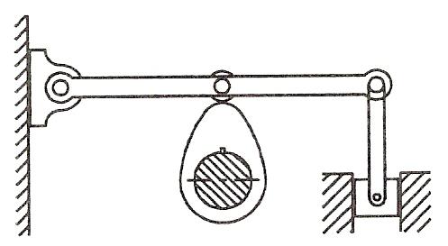
Figure 13 - Arm and Roller Follower with a Rotary Cam
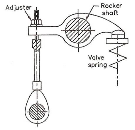
Figure 14 - Cam System from an Overhead Valve System in a Car Engine
Technical drawing is a major method of communicating and exchanging design ideas in industry. Before looking at more aspects of technical drawing we will look at designing in general, but it must be remembered that this book is about technical drawing. The purpose here is to show how technical drawing fits into the overall design process. A number of design processes can be seen in various books. Although other design processes may appear different to those described here, if you look at others carefully, you will see a general pattern in them all.
Figure 15 describes a design process in a circular flow chart form. Why is it circular? This is because unless a completed design is suitable for the purpose for which it has been designed and made, the designer will have to go back to the beginning and start all over again.
Note: in manufacturing industries, once a design has gone into manufacture, improvements of its design may well be needed from time to time. If faults show up in the design when it has been put to use, further work may be needed in order to solve the problems shown up by the faults.
As seen above, technical drawings play an important part in design problem solving. We are not dealing with the designing and making of articles, but only with the drawing skills so important in the design process. Because of this, the examples and exercises contained in its pages are based on:
Even the most skilled computer expert working as a draughtsman with a CAD system must have a good technical drawing background. Without a good knowledge of the practice of technical drawing methods learned 'at the drawing board', a CAD operator cannot produce technical drawings with his/her equipment. It is only by practising with the aid of drawing instruments that computer drawing skills can be gained. A good practical knowledge of plane and solid geometry, an understanding of the theory of orthographic projection, the use of good standard drawing conventions can only be learned by constant practice 'at the drawing board'. So - first learn how to produce good quality technical drawings 'by hand', then learn how to produce them with CAD.
Pictorial drawings show a 'picture' of an article in three dimensions, as if one were looking at the article itself. Pictorial drawings are an important part of technical drawing. There are two main reasons for this:
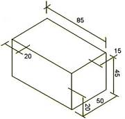
Isometric drawing is a form of pictorial drawing based on lines at 30 degrees from the horizontal. Figure 16 shows the basic idea when making an isometric drawing of a rectangular prism. Vertical lines are drawn with the aid of the right angle of a set square; lines at 30 degrees are drawn with the aid of a 30,60 set square.
When constructing an isometric drawing, all measurements must be made along the isometric axes - either the vertical lines or along the 30 degree lines. This applies even when constructing arcs or curved lines in isometric drawings. Figure 17 shows the method of finding the sizes along the isometric axes for the construction of Figure 18. Figure 19 shows how lines, which are not along the isometric axes, must be constructed from measurements taken along the axes.
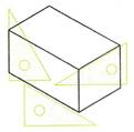
Figure 16 - Isometric Drawing of a Rectangular Prism
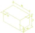
Figure 17 - Sizes must be taken along Isometric Axes
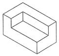
Figure 18 - Finished Isometric Drawing to the Sizes in Figure 17
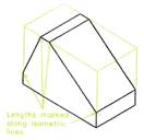
Figure 19 - Sloping Lines - Sizes must be measured along Axes
Figure 20 shows how an isometric circle is constructed:
Figure 21 shows a similar construction for circles in other isometric positions.
Figure 22 is an example of a simple isometric drawing and Figure 23 another example which includes isometric 'circles'.
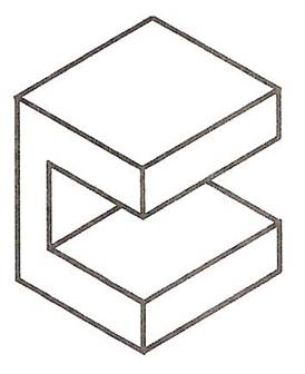
Figure 22 - Simple Isometric Drawing
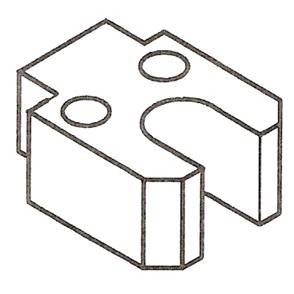
Figure 23 - Simple Isometric Drawing involving Circles
Note: The reader is advised not to use isometric ellipse templates until he or she has had sufficient practise in constructing isometric ellipses as shown in Figure 23.
Figure 24 is a simple ‘exploded’ isometric drawing; its parts have been ‘exploded’ along the isometric axes.
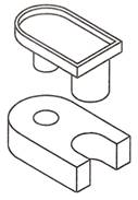
Figure 24 - Simple Exploded Isometric Drawing
Figure 25 is an exploded isometric drawing of a fork end, showing the two parts – its end piece and its rod in an exploded position. The rodis shown pulled out from the END along an isometric 30 degree axis. A rear view of the end piece is included to show that the rodfits into a hole in its back face. To construct the drawing:
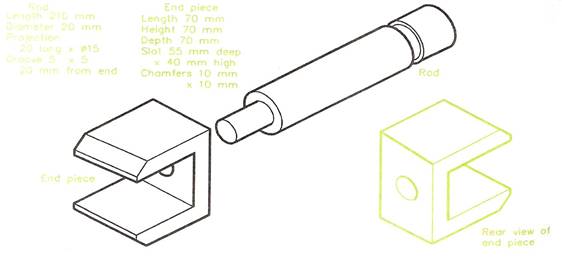
Figure 25 - Exploded Isometric Drawing
For preparing the layouts for orthographic drawings and for the necessary preparation work when designing, freehand drawing (or sketching) is a skill, which should be gained by practice. HB or B grade pencils are more suitable for freehand work than the 2H or 3H pencils, which are used for technical drawings made with the aid of instruments. If isometric and square grid papers are available, a good tip is to start learning how to draw freehand sketches on grid papers. Such grid papers can be purchased in A4 or A3 sheets with the grid lines printed in green or blue - either square grids or isometric grids are available. The spacing of the grid lines is either at 10 mm intervals or at 5 mm intervals. However, when you have gained sufficient skill in freehand drawing with the aid of grid papers, it is best to then sketch on plain paper without the grid lines. The examples given in this book are for freehand sketching on either the lines of orthographic projection or isometric drawing.
An example of a freehand drawing of a pedestal mounting as preparation for the layout of the drawing before constructing the views of an orthographic projection are shown in three examples - Figure 26 on an A3 sheet of 10 mm square grid paper, Figure 27 on a smaller sheet of grid paper and Figure 28 on plain paper without a grid. Figure 29 shows a freehand isometric drawing on isometric grid paper with the grid at 10 mm spacing. Figure 30 is a similar freehand drawing on isometric lines on plain paper without grid lines.
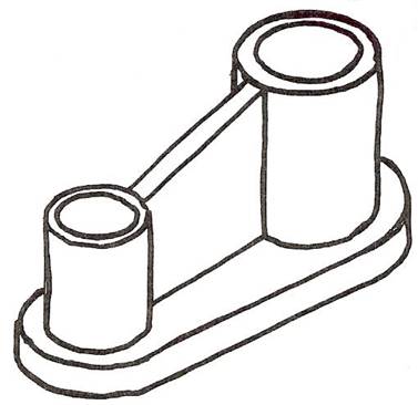
Figure 30 - Freehand Drawing on Isometric Lines on Plain Paper without Grid Lines
Figure 31 shows the method of drawing an isometric circle with the aid of instruments.
Note: This method does not produce accurate isometric circles (ellipses), but is sufficiently accurate for the construction of isometric ellipses up to about 50mm in diameter. For larger isometric ellipses, it is advisable to use the more correct method, involving the plotting of points along the ellipse curve and then drawing a fair curve through the points so obtained. If the 4-arcs method is used with larger ellipses, the resulting drawing will have a distorted appearance.
Figure 33 is an example of an isometric drawing, which involved the construction of ellipses on three faces using the 4-arcs method of construction.
The method of drawing ellipses (from circles) in isometric drawings as shown in Figure 20 is suitable for the drawing of more complicated shapes and curves in isometric drawings as shown in Figure 34. This illustration shows:
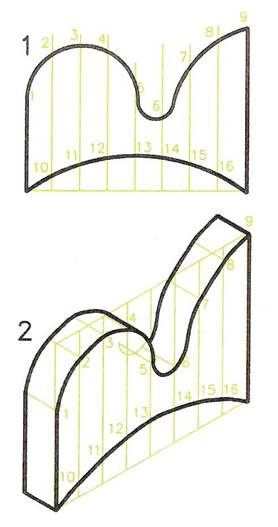
Figure 34 - Example of drawing an Isometric Curve using the Ordinate Method of Construction
If you look carefully at any object, lines along its sides appear as if they are inclined to vanish towards what is known as a Vanishing Point or V.P. this illusion can be readily seen by looking along a pair of straight railway lines. The idea of V.P.s is the basis of the two geometrical methods – one-point (or single-point) and two-point perspective drawing.
Note: True perspective drawing involves a third V.P., but 3-point perspective drawing is beyond the scope of a book of this nature. However, it must be remembered that one-point and two-point perspective drawing do not give true perspective and so may at times appear inaccurate. The two methods do, however, provide an excellent and easy method of drawing very well suited to the preparation of drawings for designs.
Figure 35 is an example of a one-point perspective of a stepped platform. Note the following:
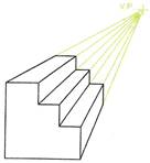
Figure 35 - Example of a One-Point Perspective Drawing
A second example is given in Figure 36, involving a semi-circular part. In this example a line from the centre of the semi-circle has been drawn to the V.P. in order to find the centre of the arc at the rear of the object.
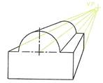
Figure 36 - One-Point Perspective Drawing which Includes an Arc
In two-point perspective two V.P.s are positioned. They must be in line with each other horizontally, but can be above or below the object being drawn. The two-point perspective drawing in Figure 37 was drawn as follows:
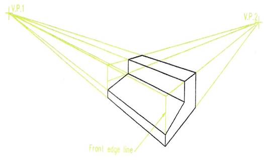
Figure 37 - Example of Two-Point Perspective
Note:
Questions on Background Notes – Module 6.Unit 1
1. When Spindles and Shafts are inserted into castings/engine blocks, what would
they commonly be slotted into and what material are they normally made from.
|
2. In this advanced age of C.A.D (Computer Aided Design) what is the purpose of
Technical Drawing?
|
|
1.
Bearings and Brushings:
|
2.
Technical Drawing: |
3.
Isometric Drawing: Isometric drawing is a form of pictorial drawing based on lines at 30 degrees from the horizontal. Figure 2 shows the basic idea when making an isometric drawing of a rectangular prism. Vertical lines are drawn with the aid of the right angle of a set square; lines at 30 degrees are drawn with the aid of a 30,60 set square.
Figure 2: Isometric Drawing of a Rectangular Prism: |
3. Continued.
|
Source: http://local.ecollege.ie/Content/APPRENTICE/liu/metalfab_notes/module6/Introduction%20to%20Fabrication%20Drawing_M6_U1.doc
Web site to visit: http://local.ecollege.ie/
Author of the text: indicated on the source document of the above text
If you are the author of the text above and you not agree to share your knowledge for teaching, research, scholarship (for fair use as indicated in the United States copyrigh low) please send us an e-mail and we will remove your text quickly. Fair use is a limitation and exception to the exclusive right granted by copyright law to the author of a creative work. In United States copyright law, fair use is a doctrine that permits limited use of copyrighted material without acquiring permission from the rights holders. Examples of fair use include commentary, search engines, criticism, news reporting, research, teaching, library archiving and scholarship. It provides for the legal, unlicensed citation or incorporation of copyrighted material in another author's work under a four-factor balancing test. (source: http://en.wikipedia.org/wiki/Fair_use)
The information of medicine and health contained in the site are of a general nature and purpose which is purely informative and for this reason may not replace in any case, the council of a doctor or a qualified entity legally to the profession.
The texts are the property of their respective authors and we thank them for giving us the opportunity to share for free to students, teachers and users of the Web their texts will used only for illustrative educational and scientific purposes only.
All the information in our site are given for nonprofit educational purposes