
A motherboard is the physical arrangement in a computer that contains the computer's basic circuitry and components. On the typical motherboard, the circuitry is imprinted or affixed to the surface of a firm planar surface and usually manufactured in a single step. The most common motherboard design in desktop computers today is the AT, based on the IBM AT motherboard. A more recent motherboard specification, ATX, improves on the AT design. In both the AT and ATX designs, the computer components included in the motherboard are:
Additional components can be added to a motherboard through its expansion slot. The electronic interface between the motherboard and the smaller boards or cards in the expansion slots is called the bus.
The best way to describe the motherboard goes along well with my human body analogy that I used for the CPU. The CPU is the brain, and the motherboard is the nervous system. Therefore, just as a person would want to have fast communication to the body parts, you want fast communication between the parts of your computer. Fast communication isn't as important as reliable communication though. If your brain wanted to move your arm, you want to be sure the nervous system can accurately and consistently carry the signals to do that! Thus, in my opinion, the motherboard is the second most important part of the computer.
The motherboard is the circuit board to which all the other components of the computer connect in some way. The video card, sound card, IDE hard drive, etc. all plug into the motherboard's various slots and connectors. The CPU also plugs into the motherboard via a Socket or a Slot.
The motherboard has been an integral part of most personal computers for more than 20 years. Think of a motherboard as a scale model of a futuristic city with many modular plug-in buildings, each using power from a common electrical system. Multiple-lane highways of various widths transport data between the buildings. The motherboard is the data and power infrastructure for the entire computer.
Motherboards (also called main boards) are actually a carryover from architecture used for years in mainframe computers. Various circuit cards performing various functions all plug into many similar sockets on a common circuit board. Each circuit card performs a unique function in the computer and gets its power from the socket as well.
Due to improvements in circuitry and packaging, motherboards have essentially stayed the same size or shrunk (in square inches), while their functionality has skyrocketed in the past 20 years. In this edition, you will learn more about how the motherboard works, and about a motherboard's many sockets and connectors.
As can be seen from the plan of the computer system, the mother, or main board is at the center of the PC computer system. Effectively it is a printed circuit board containing the central processing unit (CPU) and the memory modules (Simm's). It allows the CPU to interfaces with other parts of the computer via a 'BUS' system, into which sockets are fitted for connection of various 'expansion' boards. Also on the motherboard is the RAM memory, normally in the form of SIMM, or DIMM modules in the modern PC computer, and cache memory in the form of integrated circuits (chips). All these various components will be examined in more detail in their appropriate sections.
Modern boards utilize a Pentium CPU with four PCI and three, or four, ISA expansion slots. Most video boards now use the PCI connection. So, if you are upgrading from a 386, or 486, mother board that have a video board with VESA connectors, you may well have to purchase a new video panel.
Most Pentium boards are also fitted with controllers for Floppy Drives, 4 EIDE devices and Enhanced Parallel and Fast Serial Ports. This 'fee’s up' a couple of expansion slots for other devices
Motherboard Sizes :
Different motherboards of different vintages typically have different form factors. Form factor essentially means the size and shape of the actual motherboard. There are more than a half-dozen form factors for motherboards, with the most recent ones having the designation of NLX. Right now, the designation ATX is the most prevalent. By buying a computer with a true ATX motherboard, you are assured that you will have the ability to upgrade by being able to re-use the personal computer case with a more recent replacement ATX board design.
Motherboards have helped to keep the "personal" in personal computing since plug able components allow the user to personalize the system depending on their applications and needs. For example:
Common Motherboard Items :
A motherboard is a multi-layered printed circuit board. Copper circuit paths called traces that resemble a complicated roadmap carry signals and voltages across the motherboard. Layered fabrication techniques are used so that some layers of a board can carry data for the input/output, processor and memory buses while other layers can carry voltage and ground returns without circuit paths short-circuiting at intersections. The insulated layers are manufactured into one complete, complex "sandwich."
Chips and sockets are soldered onto the motherboard. For example, you will typically find:
Cooling fan(s) on heat sinks of processor and some video cards
Examples :
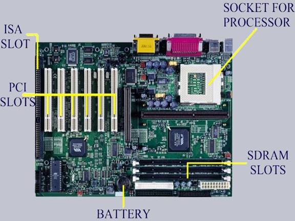
This motherboard supports one processing unit (CPU), has six PCI slots and an ISA Slot as well as an AGP Slot. The board supports 133 MHz bus speeds and ultra-direct memory access-100 (UDMA). There are four USB ports and onboard audio in the ATX form factor board.
The Abit KT-7A supports Advanced Micro Devices (AMD) processors and has the KT-133A chipset. The card slots on the Abit KT-7A, from bottom to top, shows below that ISA has one slot, PCI has six slots and AGP has one slot. A special fan cools the chipset.
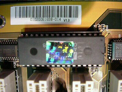
The BIOS chip is common to many motherboards.
How Have Motherboards Changed ?
Speeds, temperatures, density, faster chipset designs and component count have driven the need for circuit cooling via miniature electric fans. These fans mount inside the actual computer case. Heat sinks act like an automobile radiator and provide additional surface area to help cool a component. Replaceable fan-heat sink assemblies are often used to help dissipate the considerable amount of heat on modern processor chips. The fan-heat sink assembly conducts heat away from the chip by convection, using a layer of thermal grease between the two mating metal surfaces. Fans often have a third wire used for monitoring the speed of the fan.
Modern motherboard designs include provisions for monitoring:
PCI slots are replacing the older ISA slots, and USB ports are replacing both types of slots. USB ports can also be used to replace the usual keyboard, mouse and printer ports. Sound card function is also typically incorporated into modern motherboards. Multifunction chips are on the horizon that will do even more multiple tasks.
The additional function on the motherboard saves the motherboard manufacturer costs because:
The consumer can still upgrade function integrated on the motherboard (such as audio and game controls) so long as the motherboard manufacturer provides a means of disabling the function in order to prevent subsequent system resource conflicts.
A motherboard still may have voltages present on it even if the computer is switched off due to recent advances in power management and power controls. Always make sure that the power cord is unplugged!
Advice on Motherboards :
When buying a motherboard, follow these tips:
Avoid tweaking voltages and timings to get more speed out of a computer ("over clocking")."
Motherboard Requirements :
For maximum compatibility with Dig design hardware your computer's motherboard should be based on the Intel chipset and meet the ATX form factor specifications.
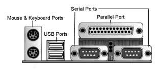
The ATX form factor is the standard in PC motherboard architecture. If you are unsure whether you have an ATX motherboard look at the back of your computer. If the ports match up with the photo below your computer most likely has an ATX motherboard.
One exception to this is with higher end workstation motherboards that include daughter boards. These are circuit board extensions off of the main motherboard that are not expansion cards. Motherboards with daughter boards do not meet the ATX specification.
1. Necessary information for the test
Before starting the test, we determined the function of each connector on the Mother Board. Fig1 shows the arrangement of connectors.
Fig 1. Connector arrangement on the Mother Board
There are 33 connectors on the outside of the Mother Board arranged by function. In the case of Timing & Control, LVDS output, and Serial & Control connectors, the group1 connector is the top one and the group7 connector is the bottom one in Fig1 (a). On the inside, group arranges connectors. Six 160-pin connectors (groups 1-6) plug into power/comm. boards and two 80-pin connectors (group7) plug into a daughter board.
We made various fan out boards, a 160 pin, an 80 pin, a 50 pin, a 40 pin, a 36 pin, a 26 pin, and a 20-pin fan out board.
We can find a pair of connected pins, a pin on the inside connector and a pin on the outside connector, by using fan out boards and Fig 1. Because of the fine pitch, direct contact to a pin with a probe or lead is difficult, but fan out boards make it easy to touch a pin.
2. Simple setup for the connectivity test
Fig 2. The resistance measurement using fan-out boards
We measured resistances for all pass-through signals. Starting with group 1, we identified a target signal then plugged the appropriate fan out board into the Mother Board. A pair of pins (or several pins in case of ground connection) with the same name were located, one pin on the inside and one pin on the outside of the board. Finally, a resistance value was measured with a FLUKE 8060A multimeter. This value included resistances of the two fans out boards, which we didn't want. Therefore we measured the resistance of each fan out board and subtracted it from the total measured resistance. The resistances of the fan out boards are shown below, in table 1. The resistance values appearing in table 2 of section 3 below exclude the portion from the two fans out boards.
Table 1. The resistances of the fan out boards |
|
Fan out board |
Resistance (ohm) |
160 pin |
0.38 |
80 pin |
0.38 |
50 pin |
0.39 |
40 pin |
0.35 |
36 pin |
0.37 |
26 pin |
0.35 |
20 pin |
0.35 |
3. Results
The resistance values, classified by the group # and signal function, are shown in table 2. Generally the measured values are distributed between 0.1 and 2.2 ohm, which we believe as acceptable. Comparing the values between groups, the measured resistances show the tendency to decrease when the group # increases from 1 to 6, which is due to the decrease of the trace length on the motherboard. Because two 80-pin connectors for group 7 are far away from the 160 pin connectors, resistances for group 7 don't follow that trend.
Because the analog discriminator sum is not used for groups 4-6,which relate to the outer layer strip detector, the table shows blank values for groups 4-6 analog sum signal connections. The below table doesn't contain the resistance values for ground connections. In fact, we had trouble with some DGND and AGND lines which are summarized at the end of this section. Except for these bad grounds, the remaining ground connections have relatively small resistance (< 0.2 ohm) regardless of the group #.
References :
http://www.basichardware.com/motherboard.html
http://www.digidesign.com/compato/mobo.html
http://whatis.techtarget.com/definition/0,sid9_gci212594, 00.html
http://www.phenix.bnl.gov/phenix/WWW/publish/mvd/ygkim/note_357/con_thru.html
Prepared by ID NUMBER
Mohammed A. Al-najem 422001524
Source: http://faculty.ksu.edu.sa/zkhan/Academics/Motherboard.doc
Web site to visit: http://faculty.ksu.edu.sa
Author of the text: indicated on the source document of the above text
If you are the author of the text above and you not agree to share your knowledge for teaching, research, scholarship (for fair use as indicated in the United States copyrigh low) please send us an e-mail and we will remove your text quickly. Fair use is a limitation and exception to the exclusive right granted by copyright law to the author of a creative work. In United States copyright law, fair use is a doctrine that permits limited use of copyrighted material without acquiring permission from the rights holders. Examples of fair use include commentary, search engines, criticism, news reporting, research, teaching, library archiving and scholarship. It provides for the legal, unlicensed citation or incorporation of copyrighted material in another author's work under a four-factor balancing test. (source: http://en.wikipedia.org/wiki/Fair_use)
The information of medicine and health contained in the site are of a general nature and purpose which is purely informative and for this reason may not replace in any case, the council of a doctor or a qualified entity legally to the profession.
The texts are the property of their respective authors and we thank them for giving us the opportunity to share for free to students, teachers and users of the Web their texts will used only for illustrative educational and scientific purposes only.
All the information in our site are given for nonprofit educational purposes