
Many materials are subjected to forces or loads when in service; examples include the aluminum alloy from which an airplane wing is constructed and the steel in an automobile axle. In such situations it is necessary to know the characteristics of the material and the operation conditions of the member during application in order to reduce the excessive deformation that led to fracture. The mechanical behavior of a material reflects its response or deformation in relation to an applied load or force. The mechanical properties include stiffness, strength, hardness, ductility, and toughness.
If a load is static or changes relatively slowly with time and is applied uniformly over a cross section or surface of a member, the mechanical behavior may be determined by a simple stress–strain test; these are most commonly conducted for metals at room temperature. There are three principal ways in which a load may be applied: namely, tension, compression, and shear.
One of the most common mechanical stress–strain tests is performed in tension. As will be seen, the tension test can be used to determine several mechanical properties of materials that are important in design.
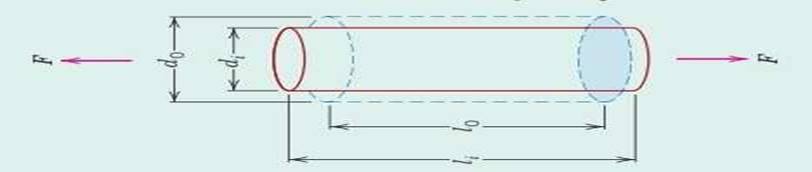
A specimen is deformed, usually to fracture, with a gradually increasing tensile load that is applied uniaxially along the long axis of a specimen. A standard tensile specimen is shown in Figure (1). A stress–strain test typically takes several minutes to perform and is destructive; that is, the test specimen is permanently deformed and usually fractured.
Figure (1): Tension test, specimen and deformation.
The output of such a tensile test is recorded (usually on a computer) as load or force versus elongation. These load–deformation characteristics are dependent on the specimen size. The load and elongation are normalized to the respective parameters of engineering stress and
engineering strain. Engineering stress (σ) is defined by the relationship:
In which (F) is the instantaneous load applied perpendicular to the specimen cross section, in units of newtons (N) or pounds force (Ibf), and (A0) is the original cross sectional area before any load is applied (m2 or in2). The units of engineering stress (referred to subsequently as just stress) are megapascals, MPa (where 1 MPa N/m2=106 N/m2), and pounds force per square inch, (psi). Engineering strain (Ԑ) is defined according to:
In which (l0) is the original length before any load is applied, and (li) is the instantaneous length. Sometimes the quantity (li-l0) is denoted as (∆l), and is the deformation elongation or change in length at some instant, as referenced to the original length.
Engineering strain (subsequently called just strain) is unit less, and sometimes strain is also expressed as a percentage, in which the strain value is mul6plied by 100.
A compression test is conducted in a manner similar to the tensile test, except that the force is compressive and the specimen contracts along the direction of the stress. Equations of tensile test are utilized to compute compressive stress and strain, respectively. By convention, a compressive force is taken to be negative, which yields a negative stress. Furthermore, since (l0) is greater than (li) compressive strains computed from above Equations are necessarily also negative. Figure
(2) show the compression test deforma6on.
Figure (2): the compression test deformation.
Tensile tests are more common because they are easier to perform; also, for most materials used in structural applications, very little additional information is obtained from the compressive tests.
Compressive tests are used when a material’s behavior under large and permanent (i.e., plastic) strains is desired, as in manufacturing applications, or when the material is brittle in tension.
The shear stress (Ƭ) is computed according to:
Where F is the load or force imposed parallel to the upper and lower faces, each of which has an area of A0. The shear strain Ƴ is defined as the tangent of the strain angle Ɵ, as indicated in the figure (3). The units for shear stress and strain are the same as for their tensile counterparts.
Torsion is a variation of pure shear, wherein a structural member is twisted in the manner of Figure (3); torsional forces produce a rotational motion about the longitudinal axis of one end of the member relative to the other. Torsional tests are normally performed on cylindrical solid shafts or tubes. A shear stress (Ƭ) is a function of the applied torque T, whereas the shear strain (Ƴ) is related to the angle of twist, (Ɵ).
Figure (3): Shear and Torsional Tests.
The degree to which a structure deforms or strains depends on the magnitude of an imposed stress. For most metals, stress and strain are proportional to each other through the relationship:
This is known as Hooke’s law, and the constant of proportionality (E) (GPa or psi) is the modulus of elasticity, or Young’s modulus. For most typical metals the magnitude of this modulus ranges between (45) GPa for magnesium and (407) GPa for tungsten. The moduli of elasticity are slightly higher for ceramic materials and range between about (70) and (500) GPa. Polymers have modulus values that are smaller than those of both metals and ceramics and lie in the range (0.007 to 4) GPa.
Deformation; in which stress and strain are proportional is called elastic Deformation, a plot of stress versus strain result in a linear relationship, as shown in figure (4). The slope of this linear segment corresponds to modulus of elasticity (E). This modulus may be thought of as stiffness, or a material’s resistance to elastic deformation.
Elastic deformation is nonpermanent, which means that when the applied load is released, the piece returns to its original shape. As shown in the stress–strain plot (figure 4-A), application of the load corresponds to moving from the origin up and along the straight line. Upon release of the load, the line is traversed in the opposite direction, back to the origin.
There are some materials (e.g., gray cast iron and many polymers) for which this elastic portion of the stress–strain curve is not linear as shown in (Figure 4-B); hence, it is not possible to determine a modulus of elasticity as described previously.
For this nonlinear behavior, either the tangent or secant modulus is normally used. The tangent modulus is taken as the slope of the stress strain curve at some specified level of stress, whereas the secant modulus represents the slope of a secant drawn from the origin to some given point of the stress–strain curve.
Figure (4): A- linear elastic behavior, B- linear elastic behavior.
Shear stress and strain are proportional to each other through the expression:
Where (G) is the shear modulus—the slope of the linear elastic region of the shear stress–strain curve.
Elastic deformation is time independent—that is, that an applied stress produces an instantaneous elastic strain that remains constant over a period of time and when the load is released, the strain is totally recovered—that is, that the strain immediately returns to zero.
In some engineering materials, the elastic deformation will continue after the stress application, and upon load release, some finite time is required for complete recovery. This time-dependent elastic behavior is known as anelasticity.
For metals, the anelastic behavior is normally small and is often neglected. However, for some polymeric materials its magnitude is significant; in this case it is termed viscoelastic behavior.
 Ex.1
Ex.1
![]()
Sol.1
When a tensile stress is imposed on a metal specimen, an elastic elongation and accompanying strain (Ԑz) result in the direction of the applied stress (arbitrarily taken to be the z direction). As a result of this elongation, there will be constrictions in the lateral (x and y) directions perpendicular to the applied stress; from these contractions, the compressive strains Ԑx and Ԑy may be determined. If the applied stress is uniaxial (only in the z direction) and the material is isotropic, then (Ԑx= Ԑy). A parameter termed Poisson’s ratio(ʋ) is defined as the ratio of the lateral and axial strains as:
For isotropic materials, shear and elastic moduli are related to each other and to Poisson’s ratio according to:
=========================================================
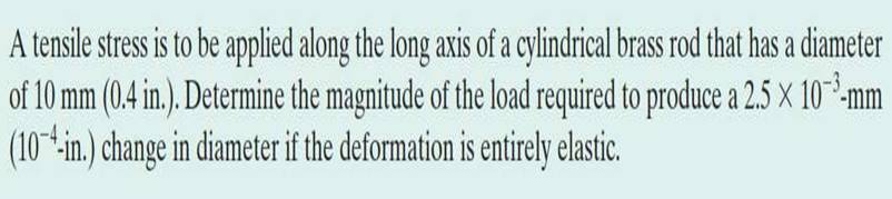
The Poisson’s ratio and elas6c modulus of brass are 0.34 and 97 GPa.
For most metallic materials, elastic deformation persists only to strains of about 0.005. As the material is deformed beyond this point, the stress is no proportional to the strain (Hooke’s law) and permanent, nonrecoverable plastic deformation occurs. Figure 5 plots schematically the tensile stress–strain behavior into the plastic region for a typical metal. The transition from elastic to plastic is a gradual one for most metals; some curvature results at the onset of plastic deformation, which increases more rapidly with rising stress.
Most structures are designed to ensure that only elastic deformation will result when a stress is applied. A structure or component that has plastically deformed or experienced a permanent change in shape may not be capable of functioning as intended. It is therefore desirable to know the stress level at which plastic deformation begins, or where the phenomenon of yielding occurs.
For metals that experience this gradual elastic–plastic transition, the point of yielding may be determined as the initial departure from linearity of the stress–strain curve; this is sometimes called the proportional limit, as indicated by point (P) in Figure (5), and represents the onset of plastic deformation.
The position of this point (P) is difficult to measure precisely. As a consequence, a convention has been established by which a straight line is constructed parallel to the elastic portion of the stress–strain curve at some specified strain offset, usually (0.002).
The stress corresponding to the intersection of this line and the stress strain curve as it bends over in the plastic region is defined as the yield strength (σy). This is demonstrated in Figure (5), and the units of yield strength are MPa or psi.
Figure (5): Typical stress–strain behavior for a metal, showing elastic and plastic deformations, the proportional limit (P), and the yield strength (σy), as determined using the 0.002 strain offset method.
For materials having a nonlinear elastic region, use of the strain offset method is not possible, and the usual practice is to define the yield strength as the stress required to produce some amount of strain (e.g., Ԑ=0.005). The magnitude of the yield strength for a metal is a measure of its resistance to plastic deformation. Yield strengths range from 35 MPa (5000 psi) for a low-strength aluminum to greater than 1400 MPa (200,000 psi) for high-strength steels.
After yielding, the stress necessary to continue plastic deformation in metals increases to a maximum, point (M) in Figure (6), and then decreases to the eventual fracture, point F. The tensile strength TS (MPa or psi) is the stress at the maximum on the engineering stress–strain curve (Figure 6). Tensile strength can be defines as the maximum stress that can be sustained by a structure in tension; if this stress is applied and maintained, fracture will result.
At this maximum stress, a small constriction or neck begins to form at some point, and all subsequent deformation is confined at this neck, as indicated by schematic specimen insets in Figure (6). This phenomenon is termed necking, and fracture ultimately occurs at the neck. The fracture strength correspond to the stress at fracture. Tensile strengths vary from 50 MPa (7000 psi) for aluminum to as high as 3000 MPa (450,000 psi) for the high-strength steels.
Typically, when the strength of a metal is cited for design purposes, the yield strength is used.
Figure (6): Typical engineering stress–strain behavior to fracture, point (F). The tensile strength (TS) is indicated at point (M). The circular insets represent the geometry of the deformed specimen at various points along the curve.
----------------------------------------------------------------------------------------------
Ex.2From the tensile stress–strain behavior for the brass specimen shown in below Figure, determine the following:
Ductility is another important mechanical property. It is a measure of the degree of plastic deformation that has been sustained at fracture. A metal that experiences very little or no plastic deformation upon fracture is termed brittle. The tensile stress–strain behaviors for both ductile and brittle metals are schematically illustrated in the figure (8).
Ductility may be expressed quantitatively as either percent elongation or the percent reduction in area. The percent elongation, (%EL), is the percentage of plastic strain at fracture, or can be represented by the following formula:
Where (lf) is the fracture length and (l0) is the original gauge length as given earlier. Percent reduction in area, (%RA), is defined as:
Where (A0) is the original cross-sectional area and (Af) is the cross sectional area at the point of fracture.
Knowledge of the ductility of materials is important for at least two reasons. First, it indicates to a designer the degree to which a structure will deform plastically before fracture. Second, it specifies the degree of allowable deformation during fabrication operations.
Figure (8): tensile stress–strain behavior for brittle and ductile
metals loaded to fracture.
Resilience is the capacity of a material to absorb energy when it is deformed elastically, upon unloading, this energy will recovered. The associated property is the modulus of resilience, Ur, which is the strain energy per unit volume required to stress a material from an unloaded state up to the point of yielding.
 Computationally, the modulus of resilience for a specimen subjected to a uniaxial tension test is just the area under engineering stress-strain curve taken to yielding as shown:
In which ԑy is the strain at yielding. Also this equation can be written as:
Thus, resilient materials are those having high yield strengths and low moduli of elasticity; such alloys are used in spring applications.
Toughness is a mechanical term that may be define as the ability of a material to absorb energy when plastically deform before fracture. For tensile test, and under static condition (low strain rate), toughness in metals can be measured by taking the area under the stress-strain curve up to the point of fracture. Even though the brittle metal has higher yield and tensile strengths, it has a lower toughness than the ductile metal.
Another mechanical property that may be important to consider is hardness, which is a measure of a material’s resistance to localized plastic deformation (e.g., a small penetration or a scratch). Early hardness tests were based on natural minerals with a scale constructed solely on the ability of one material to scratch another that was softer which termed as the Mohs scale, which ranged from (1) for soft talc to
(10) for hard diamond.
Quantitative hardness techniques have been developed over the years in which a small indenter is forced into the surface of a material to be tested under controlled conditions of load. The depth or size of the resulting indentation is measured, which is related to a hardness number; the softer the material, the larger and deeper is the indentation. Hardness tests are performed more frequently than any other mechanical test for several reasons:
Three types of hardness tests are used in hardness measurements which will discuss below.
In Brinell tests, a hard, spherical indenter is forced into the surface of the metal to be tested. The diameter of the hardened steel (or tungsten carbide) indenter is 10.00 mm. Standard loads range between 500 and 3000 kg, the load is maintained constant for a specified 6me (between 10 and 30 s). The Brinell hardness number, HB, is a function of both the magnitude of the load and the diameter of the resulting indentation as shown:
Knoop and Vickers tests (sometimes also called diamond pyramid). For
Vickers test, very small diamond indenter in the form of a square based pyramid with an apex angle of 1360 is forced into the surface of the specimen. The result is a square shaped impression, and when the load and indenter removed, the mean diagonals (d) of the indentation are measured. The Knoop test uses a diamond pyramid indenter which is designed to give a long thin impression, the length being seven times greater than the width.
Applied loads are much smaller than for the Rockwell and Brinell tests, ranging between 1 and 1000 g. The resulting impression is observed under microscope and measured; this measurement is then converted into hardness number. Careful specimen surface preparation (grinding and polishing) may be necessary to ensure a well-defined indentation that may be accurately measured. The Knoop and Vickers hardness numbers are designated by HK and HV, respectively.
The Knoop and Vickers techniques are referred to as micro-indentation testing methods on the basis of the indenter size. Both are well suited for measuring the hardness of small, selected specimen regions; furthermore, the Knoop technique is used for testing brittle materials such as ceramics.
The Rockwell tests constitute the most common method used to measure hardness because they are so simple to perform and require no special skills. Several different scales may be utilized from possible combinations of various indenters and different loads, which permit the testing of virtually all metal alloys (as well as some polymers). Indenters include spherical tungsten carbide balls having different diameters, as well as a conical diamond indenter, which is used for the hardest materials. With this system, a hardness number is determined by the difference in depth of penetration resulting from the application of the load.
--------------------------------------------------------------------------------------------------------------------------------------------------------------------------------------------
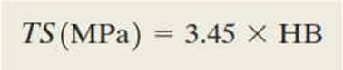
Both tensile strength and hardness are indicators of a metal’s resistance to plastic deformation. Consequently, they are roughly proportional for tensile strength as a function of the HB for cast iron, steel, and brass. The same proportionality relationship does not hold for all metals, for most steels, the HB and the tensile strength are related according to:
Source: https://uomustansiriyah.edu.iq/media/lectures/5/5_2019_06_22!06_58_00_PM.docx
Web site to visit: https://uomustansiriyah.edu.iq/
Author of the text: indicated on the source document of the above text
If you are the author of the text above and you not agree to share your knowledge for teaching, research, scholarship (for fair use as indicated in the United States copyrigh low) please send us an e-mail and we will remove your text quickly. Fair use is a limitation and exception to the exclusive right granted by copyright law to the author of a creative work. In United States copyright law, fair use is a doctrine that permits limited use of copyrighted material without acquiring permission from the rights holders. Examples of fair use include commentary, search engines, criticism, news reporting, research, teaching, library archiving and scholarship. It provides for the legal, unlicensed citation or incorporation of copyrighted material in another author's work under a four-factor balancing test. (source: http://en.wikipedia.org/wiki/Fair_use)
The information of medicine and health contained in the site are of a general nature and purpose which is purely informative and for this reason may not replace in any case, the council of a doctor or a qualified entity legally to the profession.
The texts are the property of their respective authors and we thank them for giving us the opportunity to share for free to students, teachers and users of the Web their texts will used only for illustrative educational and scientific purposes only.
All the information in our site are given for nonprofit educational purposes