
Geometric Dimensioning and Tolerancing (GD&T)
Geometric Dimensioning and Tolerancing is a language used on engineering drawings to describe a part accurately. The language consists of a well-defined set of symbols and rules to describe the size, form, orientation, and location tolerances. The need for drawing notes are reduced for describing complex geometry on a component or assembly as GD & T uses standard symbols. It is being used for many years in the automotive, aerospace and the commercial design and manufacturing industries. A reference coordinate system on a component or assembly can be easily defined with the help of GD & T. Geometric Tolerancing specifies the allowable variation for the form and the size of individual features, and the allowable variation in orientation and location between features.
3.1.1 Geometric Dimensioning
In PMI, complete information about the size and shape has to be added on the component or assembly. Adding size information to a drawing is known as dimensioning. PMI follows Baseline dimensioning in which a base line (or datum line) is established for each coordinate direction, and all dimensions are specified with respect to these baselines.
3.1.2 Tolerancing
Tolerance is defined as the permissible limit or limits of variation in a physical dimension. This variation can be in the size and/or the geometry of a component. It is needed because “No one or thing is perfect”. Tolerance is also defined as dimensioning for interchangeability as there might be variation in the dimensions during the production of the components at different times. To make the components assemble properly, it requires some standards in tolerance. The two most common standards agencies are:
Choosing the correct tolerance for a particular application depends on design intent of the part, method of manufacturing, cost and on individual’s experience. Different types of tolerance used in GD&T for size dimensions are enlisted below.
1. Limit Dimensions
Limits are defined as the maximum and minimum size that a part can obtain. The higher limit is placed above the lower limit. When both limits are placed on one line, the lower limit precedes the higher limit.
2. Plus or Minus Tolerances
Plus or minus tolerance defines a basic size and the variation around that basic size. It is further classified as unilateral tolerance and bilateral tolerance.
In this system, the variation in the dimension of the part is on one side of the basic size. Examples of unilateral tolerance are as follows:
![]() ,
, ![]() ,
, ![]()
This system is preferred in interchangeable manufacturing, especially when precision fits are required.It is easy and simple to determine deviations.
In this system, the variation in the dimension of the partis on both the sides of the basic sizebut may/may not be equally disposing about the basic size. Examples of Bilateral Tolerance are as follows:
![]() ,
, ![]()
This system is used in mass production when machine setting is done for the basic size.
3. Geometric Tolerance
Different types of tolerances used in GD&T for Geometric Tolerancing are as follows:
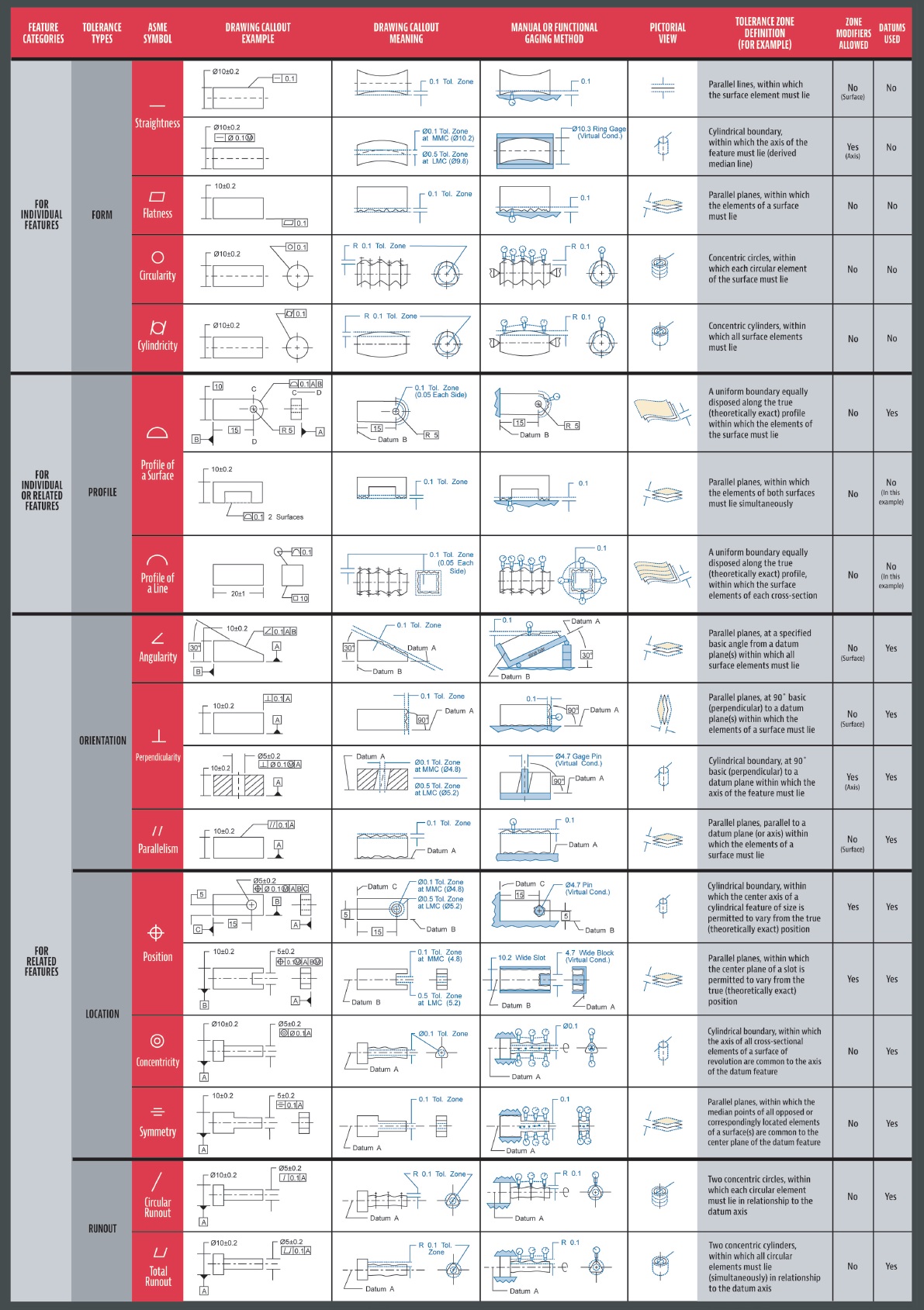
1) Form Tolerances
Form tolerances are applicable to individual features or elements of a single feature. Form tolerances are not related to datums. Following are the types of form tolerances:
a) Straightness
Straightness is a form where an element of a surface, or an axis, is a straight line. A straightness tolerance is applicable where the elements to be controlled are represented by a straight line.
b) Flatness
Flatness is the condition of a surface having all elements in one plane. A flatness tolerance specifies a tolerance region defined by two parallel planes within which the surface must lie.
c) Circularity
The roundness of circular parts or features is controlled by circularity. Cones, cylinders and spheres can define these features. The Circularity tolerance specifies where all points of a surface of a circular part must lie.It is a region bounded by two concentric circles where the radius differs by the tolerance value of the concentricity.
Figure 3 gives detailed information of all the type of form tolerances along with their symbols.
Figure 3.Form Tolerances
2. Profile Tolerance
A Profile is the outline of a part in a given plane. An uniform boundary within where the elements of the surface must lie is defined by profile tolerance. Profile tolerance is applicable in all directions. Hence, it is a three-dimensional tolerance. It can be either unilateral or bilateral. Following are the types of Profile tolerances:
a) Profile of a Line
Profile of a line tolerance governs the profile variation, either unilaterally or bilaterally, along a line element of a feature.
b) Profile of a Surface
Profile of a surface tolerance governs the variation, either unilaterally or bilaterally, on a surface.
Figure 4 gives detailed information of all the type of profile tolerances along with their symbols.
Figure 4.Profile Tolerances
3. Orientation Tolerance
Orientation tolerances control the orientation of features to a datum plane or axis. Following are the types of Orientation tolerances
a) Perpendicularity:
Perpendicularity tolerance controls how much a surface, axis, or plane can deviate from a 90-degree angle. In perpendicularity tolerance, the tolerance region is defined by two parallel planesperpendicular to a datum plane, datum axis, or axis. The surface or the axis of the feature must lie within this region.
b) Angularity:
Angularity tolerance controls how much a surface, axis, or plane can deviate from the angle described in the design specifications. In an angularity tolerance, the tolerance regionis defined by two planes at the specified angle, other than 90 degree, from a datum plane or axis. The surface or the axis of the feature must lie within this region.
c) Parallelism:
Parallelism tolerance region is the condition of a surface or center plane equidistant at all points from a datum plane, or an axis. The tolerance specifies the distance between the parallel lines, or surfaces. In parallelism tolerance, the tolerance region is defined by two parallel planes or lines parallel to a datum plane or axis.The surface or the axis of the feature must lie within this region.
Figure 5 gives detailed information of all the type of orientation tolerances along with their symbols.
Figure 5.Orientation Tolerances
4. Location Tolerance
Location Tolerances are classified in three types. They are position, concentricity, and symmetry tolerances. The center distance of feature elements are controlled by concentricity and symmetry. The coaxiality of features, the center distance between features, and the location of features is controlled by position tolerance.
a) Symmetry:
The median points of a feature are controlled by symmetry tolerance. It is applied to non-circular features. Symmetry Tolerance governs the variation of the median points between two features from a specified center plane or axis.
b) Position:
Positional tolerance varies along all directions. Hence, it is a three-dimensional geometric tolerance. It governsthe deviation in location of a feature from its true position. Features such as holes, keyway can be located from datum planes using positional tolerance. The tolerance defines a region that the axis or center plane of a feature may vary from.
c) Concentricity:
A concentricity tolerance controls a cylindrical tolerance region whose axis coincides with the datum axis. A region within which all cross-sectional axes of the feature being controlled must lie is defined by concentricity. The regionis equally oriented about the datum axis for concentricity. In concentricity,the median points of the feature, regardless of its size, must lie within the tolerance zone.
Figure 6 gives detailed information of all the type of location tolerances along with their symbols.
Figure 6.Location Tolerances
5. Runout Tolerances
Runout tolerances are three-dimensional and are applicable only to cylindrical parts, especially for parts that rotate.Following are the types of Runout tolerances:
a) Circular Runout:
Circular Runout can be defined as a two-dimensional geometric tolerance.As cylindrical part rotates circular runout controls the form, orientation, and location across multiple cross sections. It controls the cumulative variation of circularity (roundness) and coaxiality for features constructed around a datum axis. It also controls the circular elements of a surface constructed at an angle not parallel to the datum axis.
b) Total Runout:
In total runout toleranceis controlled along the entire length of, and between, two imaginary cylinders, not just at cross sections. It controls cumulative variations in circularity, coaxiality, straightness, taper, angularity, and profile of a surface. The tolerance region is an annular cylindrical volume of revolution about the center axis of the circle and concentric with the feature surface.
Figure 7 gives detailed information of all the type of runout tolerances along with their symbols.
Figure 7. Runout Tolerances
3.2 Datum
A datum is a theoretically a plane, point, or axis from which all dimensional measurement is made in PMI. The variations in the tolerances are also defined with respect to these datums. A datum feature is a physical feature of a part identified by a datum feature symbol and corresponding datum feature triangle. Datum features are selected on the basis of part function and assembly requirements. The datum features are often the features that orient (stabilize) and locate the part in its assembly.Figure 8 shows the representation of a datum on a part.
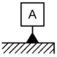
Figure 8.Representation of Datum
3.3 Feature Control Frame
A feature control frame consists of a rectangular frame that is divided into two or more blocks. It is like a basic sentence that can be read from left to right. It defines characteristic type, tolerance shape and value and datum references. The number of compartments in the feature control frame can vary.Figure 9 shows a part with Feature controlled frame which can be interpreted as follows:
The Center of the Hole Feature must be within a 0.05 diameteraltolerance zone at ‘Maximum Material Condition’ relative to datums A and B.
Figure 9.Representation of Feature Controlled Frame
3.4 Notes
Notes are information other than pictorial views and dimensions required for completing a drawing. Any additional information for manufacturing can be put on the part as a note.
3.5 Weld Symbols
Welding Symbol indicates welding joints on engineering drawings. In PMI information will consist of the location, the type of weld and the size and length of the fillet weld.
3.6 Surface Finish Symbols
Surface roughness symbol conveys manufacturing process related information only. Unless written specifically on the symbol, they do not carry the surface texture type (i.e. plated / milled / cold drawn). These symbols are given irrespective of material and its surface condition in PMI.
3.7 Balloon
This phenomenon annotates ‘Balloon’ on a part. Balloons can be used to indicate the part number associated with the ‘Bill of Materials’.
IV. ADVANTAGES OF PMI
PMI has the following advantages:
V. APPLICATIONS OF PMI
 https://www.planarinspect.com/wp-content/uploads/2021/09/Metrology-Matters-poster_GDT.pdf
Source: http://www.irdindia.in/journal_ijmer/pdf/vol3_iss6/5%20Final_PMI_Paper.docx
Web site to visit: http://www.irdindia.in
Author of the text: indicated on the source document of the above text
If you are the author of the text above and you not agree to share your knowledge for teaching, research, scholarship (for fair use as indicated in the United States copyrigh low) please send us an e-mail and we will remove your text quickly. Fair use is a limitation and exception to the exclusive right granted by copyright law to the author of a creative work. In United States copyright law, fair use is a doctrine that permits limited use of copyrighted material without acquiring permission from the rights holders. Examples of fair use include commentary, search engines, criticism, news reporting, research, teaching, library archiving and scholarship. It provides for the legal, unlicensed citation or incorporation of copyrighted material in another author's work under a four-factor balancing test. (source: http://en.wikipedia.org/wiki/Fair_use)
The information of medicine and health contained in the site are of a general nature and purpose which is purely informative and for this reason may not replace in any case, the council of a doctor or a qualified entity legally to the profession.
The texts are the property of their respective authors and we thank them for giving us the opportunity to share for free to students, teachers and users of the Web their texts will used only for illustrative educational and scientific purposes only.
All the information in our site are given for nonprofit educational purposes