
Classification of compressors:
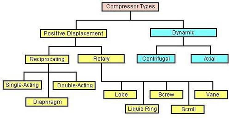
The compressors are also classified based on other aspects like
Positive Displacement compressors: Reciprocating Compressor: Single-Acting Reciprocating compressor: These are usually reciprocating compressors, which has piston working on air only in one direction. The other end of the piston is often free or open which does not perform any work. The air is compressed only on the top part of the piston. The bottom of the piston is open to crankcase and not utilized for the compression of air.
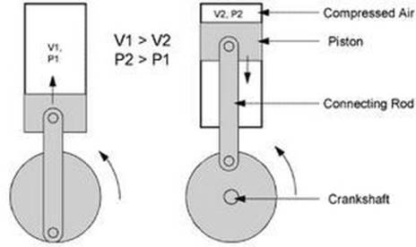
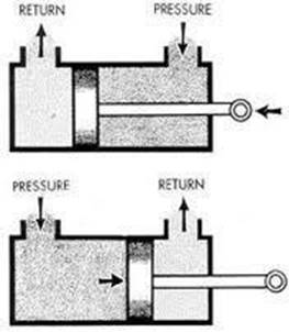
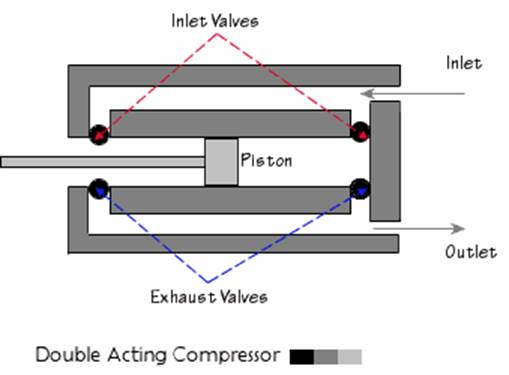
These compressors are having two sets of suction/intake and delivery valves on both sides of the piston. As the piston moves up and down, both sides of the piston is utilized in compressing the air. The intake and
delivery valves operate corresponding to the stroke of the compressor. The compressed air delivery is comparatively continuous when compared to a single-acting air compressor. Thus both sides of the pistons are effectively used in compressing the air.
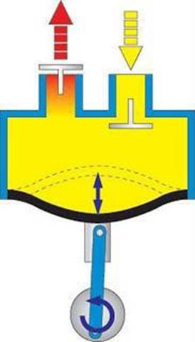
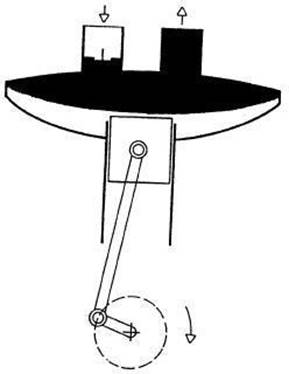
In the diaphragm compressor, the piston pushes against a diaphragm, so the air does not come in contact with the reciprocating parts. This type compressor is preferred for food preparation, pharmaceutical, and chemical industries, because no effluent from the compressor enters the fluid.
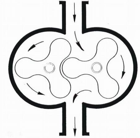
The Lobe type air compressor is very simpler type with no complicated moving parts. There are single or twin lobes attached to the drive shaft driven by the prime mover. The lobes are displaced by 90 degrees. Thus if one of the lobes is in horizontal position, the other at that particular instant will be in vertical position. Thus the air gets trapped in between these lobes and as they rotate they get compressed and delivered to the delivery line.
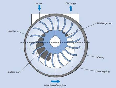
Liquid ring compressor: Liquid ring compressors require a liquid to create a seal. For medical applications, liquid ring compressors are always sealed with water but not oil. An impeller, which is offset so the impeller is not in the center of the pump housing, rotates and traps pockets of air in the space between the impeller fins and the compressor housing. The impeller is typically made of brass. As the impeller turns, there is a pocket of air that is trapped in the space between each of the fins. The trapped air is compressed between the impeller and the pump housing, sealed with the water ring. As the air is compressed, it‟s then pushed out of the pumps discharge. To avoid possible contaminants the compressor is always getting a supply of fresh sealing water. In a “once through” system, sealing water is drained and used only once, while in a “partial re-circulating” system, some (but never all) of the discharged water is re-circulated.
Vane Type compressor: The rotary slide vane-type, as illustrated in Figure, has longitudinal vanes, sliding radially in a slotted rotor mounted eccentrically in a cylinder. The centrifugal force carries the sliding vanes against the cylindrical case with the vanes forming a number of individual longitudinal cells in the eccentric annulus between the case and rotor. The suction port is located where the longitudinal cells are largest. The size of each cell is reduced by the eccentricity of the rotor as the vanes approach the discharge port, thus compressing the air. This type of compressor, looks and functions like a vane type hydraulic pump. An eccentrically mounted rotor turns in a cylindrical housing having an inlet and outlet. Vanes slide back and forth in grooves in the rotor. Air pressure or spring force keeps the tip of these vanes
in contact with the housing. Air is trapped in the compartments formed by the vanes and housing and is compressed as the rotor turns.
Screw Type compressor: The screw compressors are efficient in low air pressure requirements. Two screws rotate intermeshing with each other, thus trapping air between the screws and the compressor casing, forming pockets which progressively travel and gets squeezed and delivering it at a higher pressure which opens the delivery valve. The compressed air delivery is continuous and quiet in operation than a reciprocating compressor. Rotary air compressors are positive displacement compressors. The most common rotary air compressor is the single stage helical or spiral lobe oil flooded screw air compressor. These compressors consist of two rotors within a casing where the rotors compress the air internally. There are no valves. These units are basically oil cooled (with air cooled or water cooled oil coolers) where the oil seals the internal clearances. Since the cooling takes place right inside the compressor, the working parts never experience extreme operating temperatures. The rotary compressor, therefore, is a continuous duty, air cooled or water cooled compressor package.
Scroll Type Compressor: This type of compressor has a very unique design. There are two scrolls that look like loosely rolled up pieces of paper––one rolled inside the other. The orbiting scroll rotates inside of the stationary scroll. The air is forced into progressively smaller chambers towards the center. The compressed air is then discharged through the center of the fixed scroll. No inlet or exhaust valves are needed.
Centrifugal Compressor:
The centrifugal air compressor is a dynamic compressor which depends on transfer of energy from a rotating impeller to the air. Centrifugal compressors produce high-pressure discharge by converting angular momentum imparted by the rotating impeller (dynamic displacement). In order to do this efficiently, centrifugal compressors rotate at higher speeds than the other types of compressors. These types of compressors are also designed for higher capacity because flow through the compressor is continuous. Adjusting the inlet guide vanes is the most common method to control capacity of a centrifugal compressor. By closing the guide vanes, volumetric flows and capacity are reduced. The centrifugal air compressor is an oil free compressor by design. The oil lubricated running gear is separated from the air by shaft seals and atmospheric vents. The centrifugal air compressor is a dynamic compressor which depends on a rotating impeller to compress the air. In order to do this efficiently, centrifugal compressors must rotate at higher speeds than the other types of compressors. These types of compressors are designed for higher capacity because flow through the compressor is continuous and oil free by design.
Axial Compressor: These are similar to centrifugal compressors except the direction of air flow is axial. The blades of the compressor are mounted onto the hub and in turn onto the shaft. As the shaft rotates at a high speed, the ambient air is sucked into the compressor and then gets compressed (high speed of rotation of the blades impart energy to the air) and directed axially for further usage. An axial flow compressor, in its very simple form is called as axial flow fan, which is commonly used for domestic purposes. The pressure built depends on the number of stages. These are commonly used as vent fans in enclosed spaces, blower ducts, etc. One can find its main application in the aerospace industry, where the gas turbines drive the axial flow air compressors.
This type is generally called as blower. The discharge air pressure obtained from this type of machine is very low. The Discharge Pressure of 1 bar can be obtained in Single Stage and pressure of 2.2 bar is obtained from Stage. The discharge pressure achieved by two rotors which have separate parallel axis and rotate in opposite directions. This is the example of Positive Displacement Compressor in Rotary Type Air Compressor.
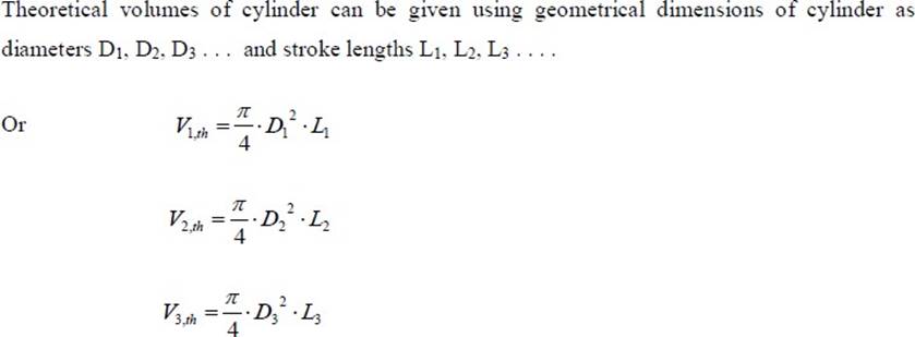
Multistage compression refers to the compression process completed in more than one stage i.e., a part of compression occurs in one cylinder and subsequently compressed air is sent to subsequent cylinders for further compression. In case it is desired to increase the compression ratio of compressor then multi-stage compression becomes inevitable. If we look at the expression for volumetric efficiency then it shows that the volumetric efficiency decreases with increase in pressure ratio. This aspect can also be explained using p-V representation shown in Figure.
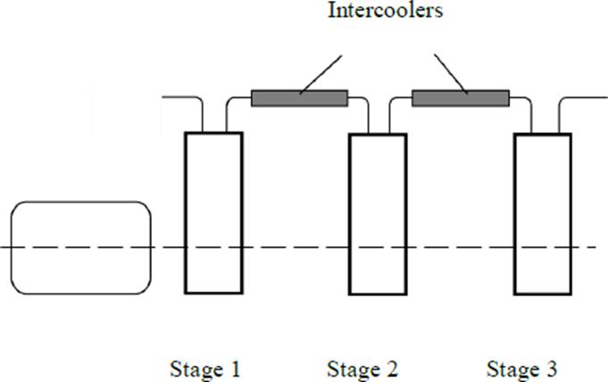
A multi-stage compressor is one in which there are several cylinders of different diameters. The intake of air in the first stage gets compressed and then it is passed over a cooler to achieve a temperature very close to ambient air. This cooled air is passed to the intermediate stage where it is again getting compressed and heated. This air is again passed over a cooler to achieve a temperature as close to ambient as possible. Then this compressed air is passed to the final or the third stage of the air compressor where it is compressed to the required pressure and delivered to the air receiver after cooling sufficiently in an after- cooler.
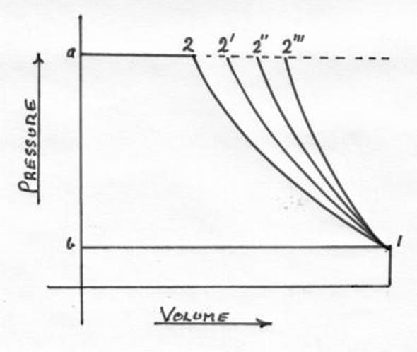
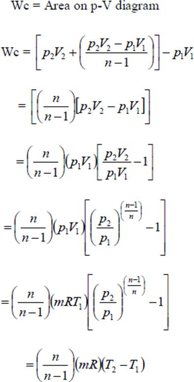
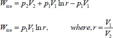
Air enters compressor at pressure p1 and is compressed upto p2. Compression work requirement can be estimated from the area below the each compression process. Area on p-V diagram shows that work requirement shall be minimum with isothermal process 1-2”. Work requirement is maximum with process 1-2 ie., adiabatic process. As a designer one shall be interested in a compressor having minimum compression work requirement. Therefore, ideally compression should occur isothermally for minimum work input. In practice it is not possible to have isothermal compression because constancy of temperature during compression can not be realized. Generally, compressors run at substantially high speed while isothermal compression requires compressor to run at very slow speed so that heat evolved during compression is dissipated out and temperature remains constant. Actually due to high speed running of compressor the compression process may be assumed to be near adiabatic or polytropic process following law of compression as Pvn=C with of „n‟ varying between 1.25 to 1.35 for air. Compression process following three processes is also shown on T-s diagram in Fig.16.4. it is thus obvious that actual compression process should be compared with isothermal compression process. A mathematical parameter called isothermal efficiency is defined for quantifying the degree of deviation of actual compression process from ideal compression process. Isothermal efficiency is defined by the ratio is isothermal work and actual indicated work in reciprocating compressor.
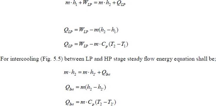
Practically, compression process is attempted to be closed to isothermal process by air/water cooling, spraying cold water during compression process. In case of multistage compression process the compression in different stages is accompanied by intercooling in between the stages. P2 V2.
Mathematically, for the compression work following polytropic process, PVn=C. Assuming negligible clearance volume the cycle work done.
In case of compressor having isothermal compression process, n = 1, ie., p1V1 = p2V2
In case of compressor having adiabatic compression process,
The isothermal efficiency of a compressor should be close to 100% which means that actual compression should occur following a process close to isothermal process. For this the mechanism be derived to maintain constant temperature during compression process. Different arrangements which can be used are:
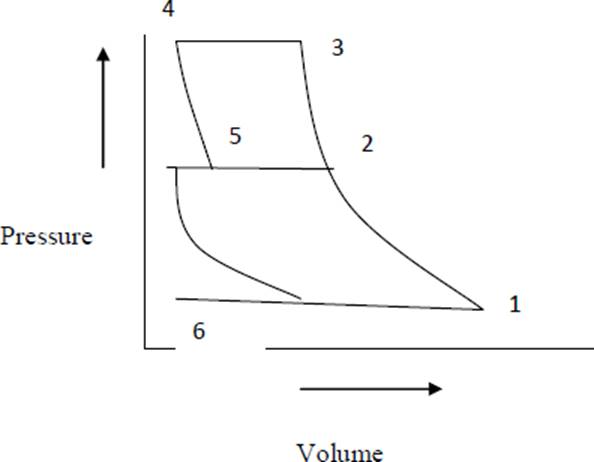
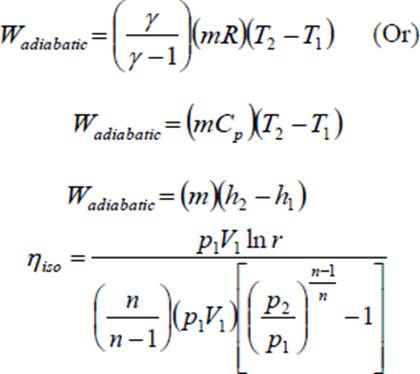
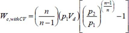
Work done in a single stage reciprocating compressor with clearance volume: Considering clearance volume: With clearance volume the cycle is represented on Figure. The work done for compression of air polytropically can be given by the are a enclosed in cycle 1-2-3-4. Clearance volume in compressors varies from 1.5% to 35% depending upon type of compressor.
In the cylinder of reciprocating compressor (V1-V4) shall be the actual volume of air delivered per cycle. Vd = V1 – V4. This (V1 – V4) is actually the volume of air in hated in the cycle and delivered subsequently.
If air is considered to behave as perfect gas then pressure, temperature, volume and mass can be inter related using perfect gas equation. The mass at state 1 may be given as m1 mass at state 2 shall be m1, but at state 3 after delivery mass reduces to m2 and at state 4 it shall be m2.
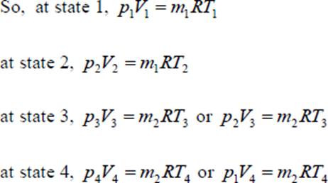
Ideally there shall be no change in temperature during suction and delivery i.e., T4 = T1 and T2 = T3 from earlier equation
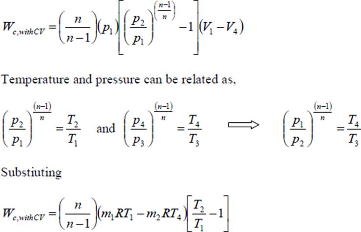
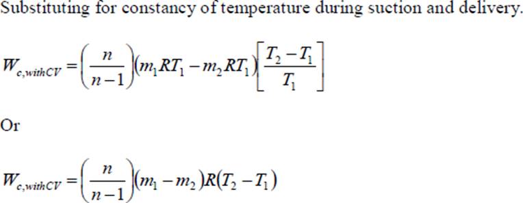
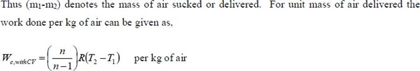
Thus from above expressions it is obvious that the clearance volume reduces the effective swept volume i.e., the mass of air handled but the work done per kg of air delivered remains unaffected. From the cycle work estimated as above the theoretical power required for running compressor shall be,
For single acting compressor running with N rpm, power input required, assuming clearance volume.
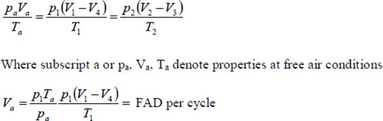
Volumetric Efficiency: Volumetric efficiency of compressor is the measure of the deviation from volume handling capacity of compressor. Mathematically, the volumetric efficiency is given by the ratio of actual volume of air sucked and swept volume of cylinder. Ideally the volume of air sucked should be equal to the swept volume of cylinder, but it is not so in actual case. Practically the volumetric efficiency lies between 60 to 90%. Volumetric efficiency can be overall volumetric efficiency and absolute volumetric efficiency as given below.


Here free air condition refers to the standard conditions. Free air condition may be taken as 1 atm or 1.01325 bar and 15oC or 288K. consideration for free air is necessary as otherwise the different compressors can not be compared using volumetric efficiency because specific volume or density of air varies with altitude. It may be seen that a compressor at datum level (sea level) shall deliver large mass than the same compressor at high altitude.
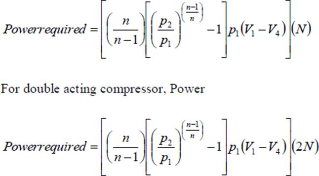
This concept is used for giving the capacity of compressor in terms of „free air delivery‟ (FAD). “Free air delivery is the volume of air delivered being reduced to free air conditions”. In case of air the free air delivery can be obtained using perfect gas equation as,
This volume Va gives „free air delivered‟ per cycle by the compressor. Absolute volumetric efficiency can be defined, using NTP conditions in place of free air conditions.
Volumetric efficiency depends on ambient pressure and temperature, suction pressure and temperature, ratio of clearance to swept volume, and pressure limits. Volumetric efficiency increases with decrease in pressure ratio in compressor.
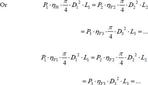
From combined p-V diagram the compressor work requirement can be given as,
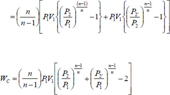
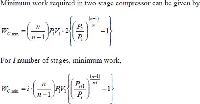
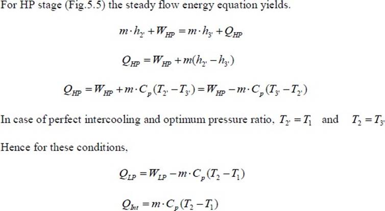
It also shows that for optimum pressure ratio the work required in different stages remains same for the assumptions made for present analysis. Due to pressure ration being equal in all stages the temperature ratios and maximum temperature in each stage remains same for perfect intercooling.
If the actual volume sucked during suction stroke is V1, V2, V3............ for different stages they by perfect gas
law, P1 V1 = RT1, P2 V2 = RT2, Pc, V3 = RT3 For perfect intercooling
![]()
Total heat rejected during compression shall be the sum of heat rejected during compression and heat extracted in intercooler for perfect intercooling.

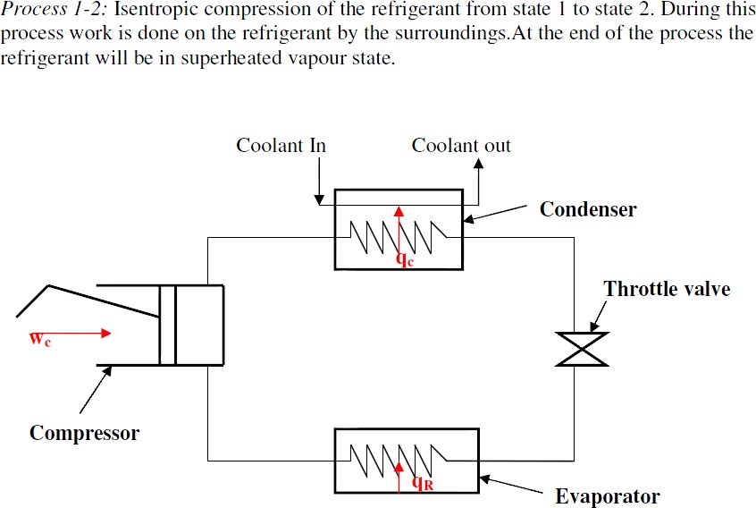
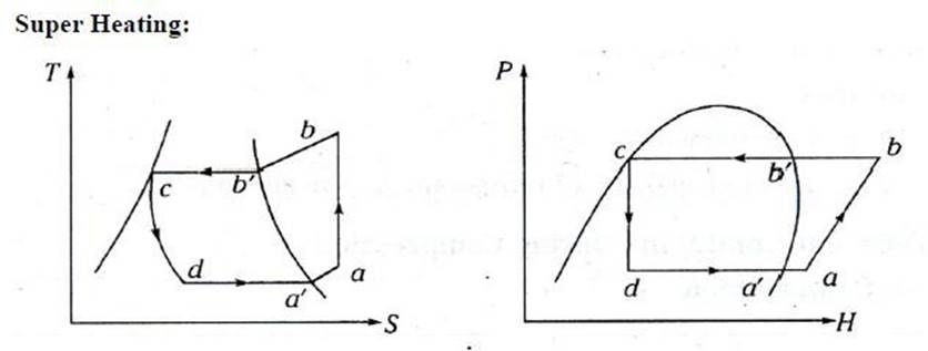
Process 2-3: Constant pressure condensation of the refrigerant in the condenser till it becomes a saturated liquid.
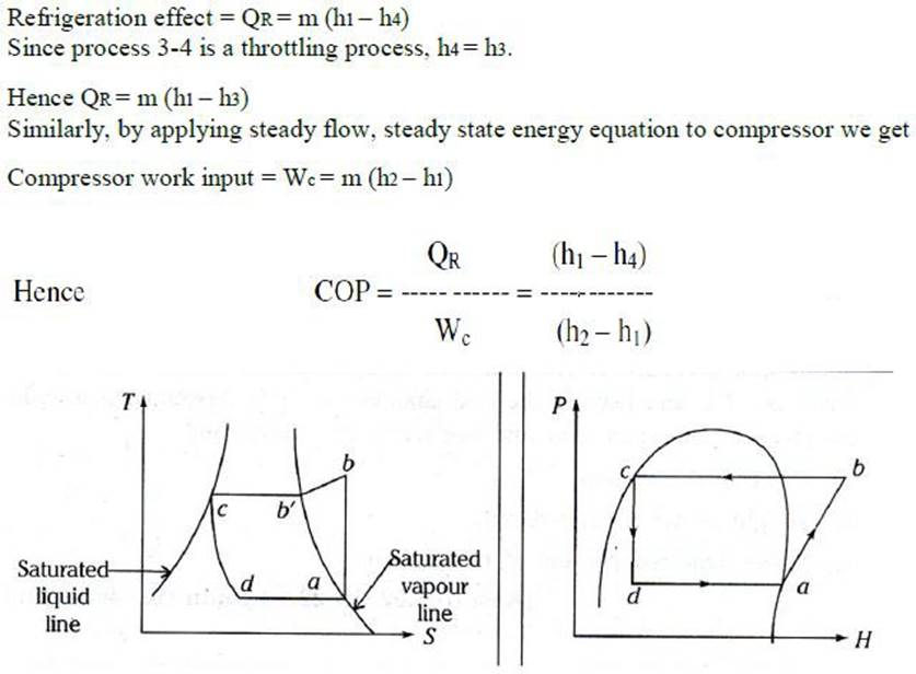
Process 3-4: Throttling expansion of the refrigerant from condenser pressure to the evaporator pressure. Process 4-1: Constant pressure vapourisation of the refrigerant in the evaporator till it becomes a dry saturated vapour. During this process heat is absorbed by the refrigerant from the place to be refrigerated. Applying steady flow steady state energy equation to the evaporator and neglecting the changes in kinetic and potential energies we have
Refrigerant A refrigerant is a fluid in a refrigerating system that by its evaporating takes the heat of the cooling coils and gives up heat by condensing the condenser. Identifying refrigerants by numbers The present practice in the refrigeration industry is to identify refrigerants by numbers. The identification system of numbering has been standardized by the American society of heating, refrigerating and air conditioning engineers (ASHRAE), some refrigerants in common use are
It obviously desirable that the refrigerant have little effect on people
Although refrigerants are entirely sealed from the atmosphere, leaks are bound to develop. If the refrigerant is inflammable and the system is located where ignition of the refrigerant may occur, a great hazard is involved.
An ideal refrigerant must have low boiling temperature at atmospheric pressure
An ideal refrigerant must have a very low freezing point because the refrigerant should not freeze at low evaporator temperatures.
In order to avoid the leakage of the atmosphere air and also to enable the detection of the leakage of the refrigerant, both the Evaporator and condenser pressure should be slightly above the atmosphere pressure.
An ideal refrigerant must not decompose under operating conditions..
The Latent heat of Evaporation must be very high so that a minimum amount of refrigerant will accomplish the desired result; in other words, it increases the refrigeration effect
The Specific Volume of the refrigerant must be low. The lower specific volume of the refrigerant at the compressor reduces the size of the compressor.
A good refrigerant must have low specific heat when it is in liquid state and high specific heat when it is vaporized
The viscosity of the refrigerant t both the liquid and vapour state must be very low as improved the heat transfer and reduces the pumping pressure.
A good refrigerant should be non-corrosive to prevent the corrosion of the metallic parts of the refrigerator.
A good refrigerant must be odourless, otherwise some foodstuff such as meat, butter, etc. loses their taste
A good refrigerant must be not react with the lubricating oil used in the refrigerator for lubricating the parts of the compressor.
Ton of refrigeration: Amount of heat required to Melt a Ton of Ice in a 24/h Period One ton of refrigeration is the heat required to melt 1 ton of ice in 24 hrs. That is, a refrigeration machine rated at 1 ton cools as much in 24 hrs. as 1 ton of ice would by melting in the same period. The heat required is the product of the latent heat of fusion and the mass in kg. Q = mH, 1 ton = 907 kg latent heat of fusion: H = 340 kJ/kg Q = 907*340 = 308380 kJ The power required is then:
P = E/t = Q/t = 308380 kJ/24 hr = 308380/(24*3600) = 3.57 kw Note: 1 watt = 1 J/s so that 1 kw = 1 kJ/s
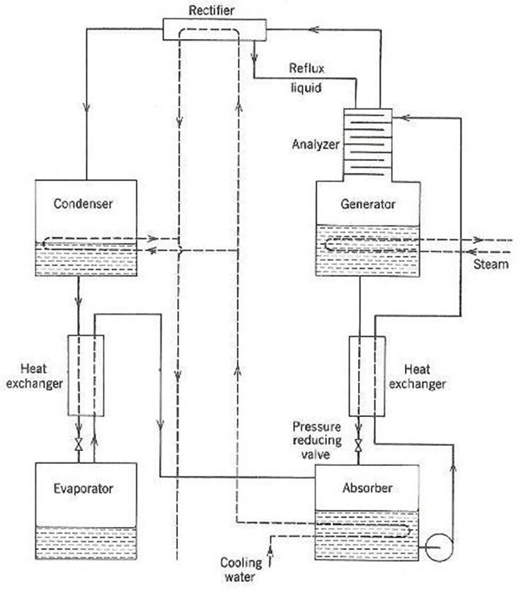
some water particles also get carried away with ammonia refrigerant, so it is important to pass this refrigerant through analyzer.
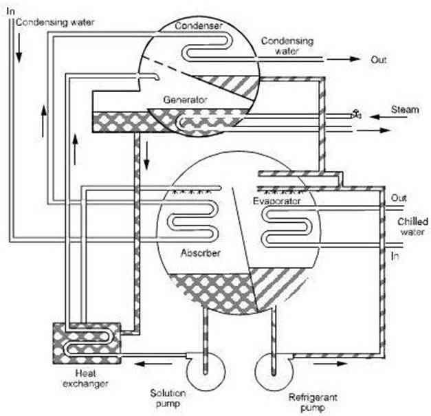
This refrigeration system is used for large tonnage capacity. In this system, lithium-bromide is acting as the absorbent and water is acting as refrigerant. Thus in the absorber the lithium bromide absorbent absorbs the water refrigerant and solution of water and lithium bromide is formed. This solution is pumped by the pump to the generator where the solution is heated.
The water refrigerant gets vaporized and moves to the condenser where it is heated while lithium bromide flows back to the absorber where it further absorbs water coming from the evaporator. The water-lithium bromide vapor absorption system is used in a number of air conditioning applications. This system is useful for the applications where the temperature required is more than 32 degree F.
Here are some special features of the water and lithium bromide in absorption refrigeration system: 1) As such lithium bromide has great affinity for water vapor, however, when the water-lithium bromide solution is formed, they are not completely soluble with each other under all the operating conditions of the absorption refrigeration system. Hence, when the water-lithium bromide absorption refrigeration system is being designed, the designer must take care that such conditions would not be created where the crystallization and precipitation of lithium bromide would occur.
Let us see various parts of the water-lithium bromide absorption refrigeration and their working (please refer the figure above):
As seen in the image above, the condenser water is used to cool the water refrigerant in the condenser and the water-Li Br solution in the absorber. Steam is used for heating water-Li Br solution in the generator. To change the capacity of this water-Li Br absorption refrigeration system the concentration of Li Br can be changed.
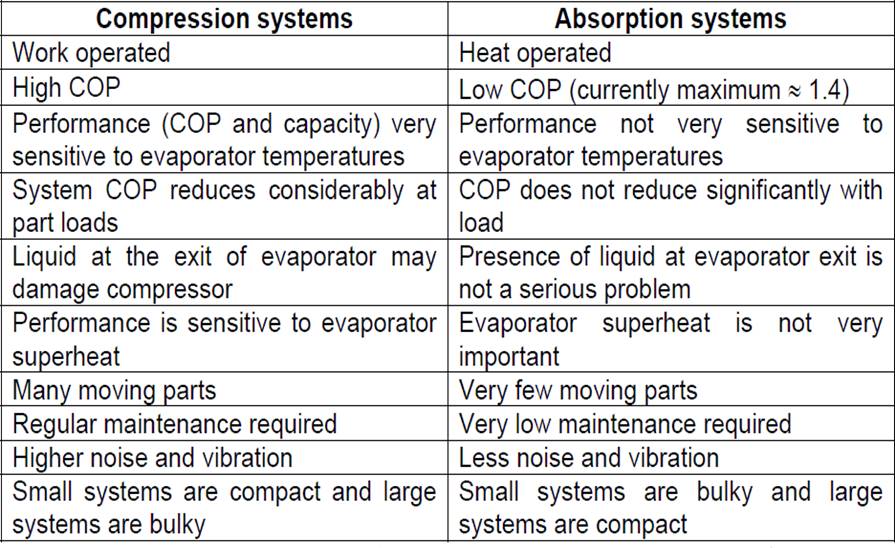
Comparison between vapour compression and vapour absorption systems:
Cooling Load Calculation:
Load due to heat transfer:
1.Cooling Load Temperature Difference
The space sensible cooling load Qrs is calculated as:
Sensible Heat
Sensible heat is the heat absorbed or given off by a substance that is NOT in the process of changing its physical state. Sensible heat can be sensed, or measured, with a thermometer, and the addition or removal of sensible heat will always cause a change in the temperature of the substance.
Latent heat is the heat absorbed or given off by a substance while it is changing its physical state. The heat absorbed or given off does NOT cause a temperature change in the substance- the heat is latent or hidden. In other words, sensible heat is the heat that affects the temperature of things; latent heat is the heat that affects the physical state of things.
It is defined as the ratio of gross sensible heat to the gross total heat. GSHF= GSH/GTH
Effective Sensible Heat Factor: It is the ratio of effective room sensible heat to the effective room total heat. ESHF= ERSH/ERTH. Room Sensible Heat Factor: It is the ratio of room sensible heat to the room total heat.
Central Systems: The central air conditioning system is used for cooling big buildings, houses, offices, entire hotels, gyms, movie theaters, factories etc. If the whole building is to be air conditioned, HVAC engineers find that putting individual units in each of the rooms is very expensive initially as well in the long run. The central air conditioning system is comprised of a huge compressor that has the capacity to produce hundreds of tons of air conditioning. Cooling big halls, malls, huge spaces, galleries etc is usually only feasible with central conditioning units.
A unitary air conditioning system comprises an outdoor unit including a compressor for compressing a refrigerant, an outdoor heat exchanger for heat exchange of the refrigerant and an expander connected to the outdoor heat exchanger, for expanding the refrigerant; a duct installed inside a zone of a building; a central blower unit having a heat exchanger connected to the outdoor unit through a first refrigerant pipe and a blower for supplying the air heat-exchanged bythe heat exchanger to the duct; and an individual blower unit including a heat exchanger connected to the outdoor unit through a second refrigerant pipe and a fan for sending the air heat-exchanged by the heat exchanger and disposed in a zone in the building, for individually cooling or heating the zone. Accordingly, cooling or heating operation is performed on each zone of the building, and simultaneously, additional individual heating or cooling operation can be performed on a specific space, so that a cost can be reduced, and cooling or heating in the building can be efficiently performed.
Window Air-conditioning System: It is the most commonly used air conditioner for single rooms. In this air conditioner all the components, namely the compressor, condenser, expansion valve or coil, evaporator and cooling coil are enclosed in a single box. This unit is fitted in a slot made in the wall of the room, or often a window sill.
Windows air conditioners are one of the most widely used types of air conditioners because they are the simplest form of the air conditioning systems. Window air conditioner comprises of the rigid base on which all the parts of the window air conditioner are assembled. The base is assembled inside the casing which is fitted into the wall or the window of the room in which the air conditioner is fitted. The whole
assembly of the window air conditioner can be divided into two compartments: the room side, which is also the cooling side and the outdoor side from where the heat absorbed by the room air is liberated to the atmosphere. The room side and outdoor side are separated from each other by an insulated partition enclosed inside the window air conditioner assembly (refer fig 1 below).
In the front of the window air conditioner on the room side there is beautifully decorated front panel on which the supply and return air grills are fitted (the whole front panel itself is commonly called as front grill). The louvers fitted in the supply air grills are adjustable so as tosupply the air in desired direction. There is also one opening in the grill that allows access to the control panel or operating panel in front of the window air conditioner.
assembly of the blower, the condenser fan and the motor highly compact. Split Air- Conditioning System:
The split air conditioner comprises of two parts: the outdoor unit and the indoor unit. The outdoor unit, fitted outside the room, houses components like the compressor, condenser and expansion valve. The indoor unit comprises the evaporator or cooling coil and the cooling fan. For this unit you don’t have to make any slot in the wall of the room. Further, the present day split units have aesthetic looks and add to the beauty of the room. The split air conditioner can be used to cool one or two rooms.
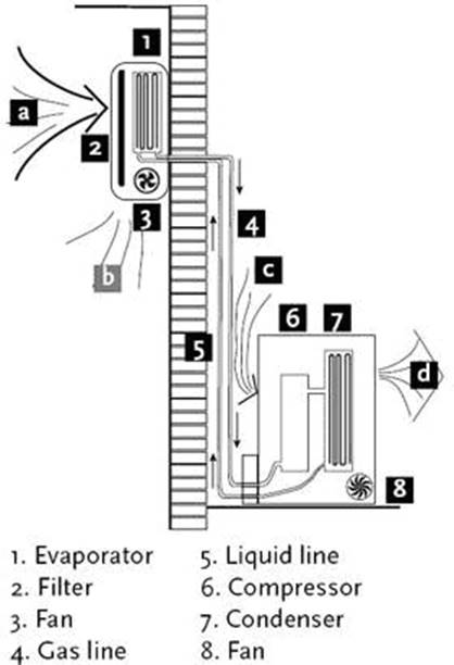
The cooling coil is a copper coil made of number turns of the copper tubing with one or more rows depending on the capacity of the air conditioning system. The cooling coil is covered with the aluminum fins so that the maximum amount of heat can be transferred from the coil to the air inside the room. The refrigerant from the tubing at very low temperature and very low pressure enters the cooling coil. The blower absorbs the hot room air or the atmospheric air and in doing so the air passes over the cooling coil which leads to the cooling of the air. This air is then blown to the room where the cooling effect has to be produced. The air, after producing the cooling effect is again sucked by the blower and the process of cooling the room continues.
After absorbing the heat from the room air, the temperature of the refrigerant inside the cooling coil becomes high and it flows back through the return copper tubing to the compressor inside the outdoor unit. The refrigerant tubing supplying the refrigerant from the outdoor unit to the indoor unit and that supplying the refrigerant from indoor unit to the outdoor unit are both covered with the insulation tape.
The air filter is very important part of the indoor unit. It removes all the dirt particles from the room air and helps supplying clean air to the room. The air filter in the wall mounted type of the indoor unit is placed just before the cooling coil. When the blower sucks the hot room air, it is first passed through the air filter and then though the cooling coil. Thus the clean air at low temperature is supplied into the room by the blower.
Inside the indoor unit there is also a long blower that sucks the room air or the atmospheric air. It is an induced type of blower and while is sucks the room air it is passed over the cooling coil and the filter due to which the temperature of the air reduces and all the dirt from it is removed. The blower sucks the hot and unclean air from the room and supplies cool and clean air back. The shaft of the blower rotates inside the bushes and it is connected to a small multiple speed motor, thus the speed of the blower can be changed. When the fan speed is changed with the remote it is the speed of the blower that changes.
Due to the low temperature refrigerant inside the cooling coil, its temperature is very low, usually much below the dew point temperature of the room air. When the room air is passed over the cooling due the suction force of the blower, the temperature of the air becomes very low and reaches levels below its dew point temperature. Due to this the water vapor present in the air gets condensed and dew or water drops are formed on the surface of the cooling coil. These water drops fall off the cooling coil and are collected in a small space inside the indoor unit. To remove the water from this space the drain pipe is connected from this space extending to the some external place outside the room where water can be disposed off. Thus the drain pipe helps removing dew water collected inside the indoor unit. To remove the water efficiently the indoor unit has to be a tilted by a very small angle of about 2 to 3 degrees so that the water can be collected in the space easily and drained out. If this angle is in opposite direction, all the water will get drained inside the room. Also, the if the tilt angle is too high, the indoor unit will shabby inside the room.
The cool air supplied by the blower is passed into the room through louvers. The louvers help changing the angle or direction in which the air needs to be supplied into the room as per the requirements. With louvers one easily change the direction in which the maximum amount of the cooled air has to be passed.
There are two types of louvers: horizontal and vertical. The horizontal louvers are connected to a small motor and there position can set by the remote control. Once can set a fixed position for the horizontal louvers so that chilled air is passed in a particular direction only or one can keep it in rotation mode so that the fresh air is supplied throughout the room. The vertical louvers areoperated manually and one can easily change their position as per the requirements. The horizontal louvers control flow of air in upper and downward directions of the room, while vertical louvers control movement of air in left and right directions.
Source: http://fmcet.in/MECH/ME6404_uw.pdf
Web site to visit: http://fmcet.in
Author of the text: indicated on the source document of the above text
If you are the author of the text above and you not agree to share your knowledge for teaching, research, scholarship (for fair use as indicated in the United States copyrigh low) please send us an e-mail and we will remove your text quickly. Fair use is a limitation and exception to the exclusive right granted by copyright law to the author of a creative work. In United States copyright law, fair use is a doctrine that permits limited use of copyrighted material without acquiring permission from the rights holders. Examples of fair use include commentary, search engines, criticism, news reporting, research, teaching, library archiving and scholarship. It provides for the legal, unlicensed citation or incorporation of copyrighted material in another author's work under a four-factor balancing test. (source: http://en.wikipedia.org/wiki/Fair_use)
The information of medicine and health contained in the site are of a general nature and purpose which is purely informative and for this reason may not replace in any case, the council of a doctor or a qualified entity legally to the profession.
The texts are the property of their respective authors and we thank them for giving us the opportunity to share for free to students, teachers and users of the Web their texts will used only for illustrative educational and scientific purposes only.
All the information in our site are given for nonprofit educational purposes