
Starter Motor types , construction and characteristics
Reducing electrical and mechanical stress at start-up, the starting current of an AC motor can vary from 3 to 7times the nominal current. This is because a large amount of energy is required to magnetise the motor enough to overcome the inertia the system has at standstill. The high current drawn from the network can cause problems such as voltage drop, high transients and, in some cases, uncontrolled shutdown. High starting current also causes great mechanical stress on the motor’s rotor bars and windings, and can affect the driven equipment and the foundations. Several starting methods exist, all aiming to reduce these stresses.
The load, the motor and the supply network determine the most appropriate starting method. When selecting and dimensioning the starting equipment and any protective devices, the following factors must be taken into account:
−− The voltage drop in the supply network when starting the motor
−− The required load torque during start
−− The required starting time
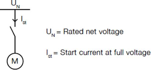
Direct on line starting is suitable for stable supplies and mechanically stiff and well- dimensioned shaft systems. It is the simplest, cheapest and most common starting method. Starting equipment for small motors that do not start and stop frequently is simple, often consisting of a hand operated motor protection circuit breaker. Larger motors and motors that start and stop frequently, or have some kind of control system, normally use a direct-on-line starter which can consist of a contactor plus overload protection, such as a thermal relay.
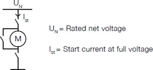
Most low voltage motors can be connected to run at either 400 V with delta connection or at 690 V with star connection. This flexibility can also be used to start the motor with a lower voltage. Star/delta connection gives a low starting current of only about one-third of that during direct-on-line starting, although this also reduces the starting torque to about 25%.
The motor is started with Y-connection and accelerated as far as possible, then switched to D-connection. This method can only be used with induction motors delta connected for the supply voltage.
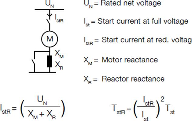
By connecting a coil with an iron core (a reactor) in series with the motor during start, the starting current is limited in proportion with the voltage. However, this also means a substantial (quadratic) reduction in the available starting torque.
The advantage of this method is its low cost in comparison with other methods.
The effect of auto transformer start is similar to that of reactor start. Using a transformer to limit the voltage reduces the starting current and the torque, but less so than the reactor start. The method is more expensive than reactor start.
By storing the power required for magnetisation in capacitor banks, it is possible to start with full starting torque without disturbing the network. To avoid over-compensation, the capacitor bank must be uncoupled after start-up. The disadvantages of this method are the high cost, and the large space requirement of the capacitor banks.
Soft starters are based on semiconductors, which, via a power circuit and a control circuit, initially reduces the motor voltage, resulting in lower motor torque. During the starting process, the soft starter progressively increases the motor voltage so that the motor becomes strong enough to accelerate the load to rated speed without causing torque or current peaks. Soft starters can also be used to control the stopping of a process. Soft starters are less costly than frequency converters but like frequency converters, they may inject harmonic currents into the grid, disrupting other processes.
Although a frequency converter is designed for continuous feeding of motors, it can also be used for start-up only. The frequency converter enables low starting current because the motor can produce rated torque at rated current from zero to full speed. As the price of frequency converters continues to drop, they are increasingly being used in applications where soft starters would previously have been used. However in most cases they are still more expensive than soft starters, and like these, they inject harmonic currents into the network.
Rheostat starting can only be used with slip ring motors. On these motors, the resistance of the rotor circuits can be increased with an external resistor. This method is usually chosen when the supply net is weak and the required starting torque and moment of inertia are very high. By switching in the additional resistances in steps, normally 4 to 7 steps, the desired acceleration torque can be obtained. The normal DOL starting equipment also required.
As a very general guide the stalled (locked) starter torque required per litre of engine capacity at the starting limit temperature is as shown in Table. A greater torque is required for engines with a lower number of cylinders due to the greater piston displacement per cylinder. This will determine the peak torque values. The other main factor is compression ratio.
To illustrate the link between torque and power, we can assume that, under the worst conditions (_20 ° C), a four-cylinder 2-litre engine requires 480 Nm to overcome static friction and 160 Nm to maintain the minimum cranking speed of 100 rev/min. With a starter pinion-to- ring gear ratio of 10 : 1,the motor must therefore, be able to produce a maximum stalled torque
of 48 Nm and a driving torque of 16 Nm. This is working on the assumption that stalled torque is generally three to four times the cranking torque.
Inertia starters
In all standard motor vehicle applications it is necessary to connect the starter to the engine ring gear only during the starting phase. If the connection remained permanent, the excessive speed at which the starter would be driven by the engine would destroy the motor almost immediately. The inertia type of starter motor has been the technique used for over 80 years, but is now becoming redundant. The starter shown in Figure shows the Lucas M35J type. It is a four-pole, four-brush machine and was used on small to medium-sized petrol engined vehicles. It is capable of producing 9.6 Nm with a current draw of 350 A. The M35J uses a face- type commutator and axially aligned brush gear. The fields are wave wound and are earthed to the starter yoke. The starter engages with the flywheel ring gear by means of a small pinion. The toothed pinion and a sleeve splined on to the armature shaft are threaded such that when the starter is operated, via a remote relay, the armature will cause the sleeve to rotate inside the pinion. The pinion remains still due to its inertia and, because of the screwed sleeve rotating inside it, the pinion is moved to mesh with the ring gear.
When the engine fires and runs under its own power, the pinion is driven faster than the armature shaft. This causes the pinion to be screwed back along the sleeve and out of engagement with the flywheel. The main spring acts as a buffer when the pinion first takes up the driving torque and also acts as a buffer when the engine throws the pinion back out of mesh.
One of the main problems with this type of starter was the aggressive nature of the engagement. This tended to cause the pinion and ring gear to wear prematurely. In some applications the pinion tended to fall out of mesh when cranking due to the engine almost, but not quite, running. The pinion was also prone to seizure often due to contamination by dust from the clutch. This was often compounded by application of oil to the pinion mechanism, which tended to attract even more dust and thus prevent engagement. The pre-engaged starter motor has largely overcome these problems.
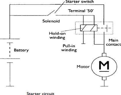
Pre-engaged starters are fitted to the majority of vehicles in use today. They provide a positive engagement with the ring gear, as full power is not applied until the pinion is fully in mesh. They prevent premature ejection as the pinion is held into mesh by the action of a solenoid. A one-way clutch is incorporated into the pinion to prevent the starter motor being driven by the engine. One example of a pre-engaged starter in common use is shown in Figure.
The basic operation of the pre-engaged starter is as follows. When the key switch is operated, a supply is made to terminal 50 on the solenoid. This causes two windings to be energized, the hold-on winding and the pull-in winding. Note that the pull-in winding is of very low resistance and hence a high current flows. This winding is connected in series with the motor circuit and the current flowing will allow the motor to rotate slowly to facilitate engagement. At the same time, the magnetism created in the solenoid attracts the plunger and, via an operating lever, pushes the pinion into mesh with the flywheel ring gear. When the pinion is fully in mesh the plunger, at the end of its travel, causes a heavy-duty set of copper contacts to close. These contacts now supply full battery power to the main circuit of the starter motor. When the main contacts are closed, the pull-in winding is effectively switched off due to equal voltage supply on both ends. The hold-on winding holds the plunger in position as long as the solenoid is supplied from the key switch. When the engine starts and the key is released, the main supply is removed and the plunger and pinion return to their rest positions under spring tension. A lost motion spring located on the plunger ensures that the main contacts open before the pinion is retracted from mesh.
During engagement, if the teeth of the pinion hit the teeth of the flywheel (tooth to tooth abutment), the main contacts are allowed to close due to the engagement spring being compressed. This allows the motor to rotate under power and the pinion will slip into mesh.
Figure shows a sectioned view of a one-way clutch assembly. The torque developed by the starter is passed through the clutch to the ring gear. The purpose of this free-wheeling device is to prevent the starter being driven at an excessively high speed if the pinion is held in mesh after the engine has started. The clutch consists of a driving and driven member with several rollers between the two. The rollers are spring loaded and either wedge-lock the two members together by being compressed against the springs, or free-wheel in the opposite direction. Many variations of the pre-engaged starter are in common use, but all work on similar lines to the above description. The wound field type of motor has now largely been replaced by the permanent magnet version.
Permanent magnet starters began to appear on production vehicles in the late 1980s. The two main advantages of these motors, compared with conventional types, are less weight and smaller size. This makes the permanent magnet starter a popular choice by vehicle manufacturers as, due to the lower lines of today’s cars, less space is now available for engine electrical systems. The reduction in weight provides a contribution towards reducing fuel consumption. The standard permanent magnet starters currently available are suitable for use on spark ignition engines up to about 2 litre capacity. They are rated in the region of 1kW. The principle of operation is similar in most respects to the conventional pre-engaged starter motor. The main
difference being the replacement of field windings and pole shoes with high quality permanent magnets. The reduction in weight is in the region of 15% and the diameter of the yoke can be reduced by a similar factor.
Permanent magnets provide constant excitation and it would be reasonable to expect the speed and torque characteristic to be constant. However, due to the fall in battery voltage under load and the low resistance of the armature windings, the characteristic is comparable to series wound motors. In some cases, flux concentrating pieces or interpoles are used between the main magnets. Due to the warping effect of the magnetic field, this tends to make the characteristic curve very similar to that of the series motor.
Development by some manufacturers has also taken place in the construction of the brushes. A copper and graphite mix is used but the brushes are made in two parts allowing a higher copper content in the power zone and a higher graphite content in the commutation zone. This results in increased service life and a reduction in voltage drop, giving improved starter power.
For applications with a higher power requirement, permanent magnet motors with intermediate transmission have been developed. These allow the armature to rotate at a higher and more efficient speed whilst still providing the torque, due to the gear reduction. Permanent magnet starters with intermediate transmission are available with power outputs of about 1.7 kW and are suitable for spark ignition engines up to about 3 litres, or compression ignition engines up to about 1.6 litres. This form of permanent magnet motor can give a weight saving of up to 40%. The principle of operation is again similar to the conventional pre-engaged starter. The intermediate transmission, is of the epicyclic type. The sun gear is on the armature shaft and the planet carrier drives the pinion. The ring gear or annulus remains stationary and also acts as an intermediate bearing. This arrangement of gears gives a reduction ratio of about 5 : 1. This can be calculated by the formula:
Ratio=AS/S
where A =number of teeth on the annulus, and S =number of teeth on the sun gear.
The annulus gear in some types is constructed from a high grade polyamide compound with mineral additives to improve strength and wear resistance.
The sun and planet gears are conventional steel. This combination of materials gives a quieter and more efficient operation.
The subject area of this book is primarily the electrical equipment on cars. This short section is included for interest, hence further reference should be made to other sources for greater detail about heavy vehicle starters.
The types of starter that are available for heavy duty applications are as many and varied as the applications they serve. In general, higher voltages are used, which may be up to 110 V in specialist cases, and two starters may even be running in parallel for very high power and torque requirements.
Large road vehicles are normally 24 V and employ a wide range of starters. In some cases the design is simply a large and heavy duty version of the pre-engaged type discussed earlier. This starter may also be fitted with a thermal cut-out to prevent overheating damage
due to excessive cranking. Rated at 8.5kW, it is capable of producing over 80 Nm torque at
1000 rev/min. Other methods of engaging the pinion include sliding the whole armature or pushing the pinion with a rod through a hollow armature. This type uses a solenoid to push the pinion into mesh via a rod through the centre of the armature. Sliding-armature-type starters work by positioning the field windings forwards from the main armature body, such that the armature is attracted forwards when power is applied. A trip lever mechanism will then only allow full power when the armature has caused the pinion to mesh.
A device called a ‘dynastart’ was used on a number of vehicles from the 1930s through to the 1960s.This device was a combination of the starter and a dynamo. The device, directly mounted on the crankshaft, was a compromise and hence not very efficient. The method is now known as an Integrated Starter Alternator Damper (ISAD). It consists of an electric motor, which functions as a control element between the engine and the transmission, and can also be used to start the engine and deliver electrical power to the batteries and the rest of the vehicle systems. The electric motor replaces the mass of the flywheel. The motor transfers the drive from the engine and is also able to act as a damper/vibration absorber unit. The damping effect is achieved by a rotation capacitor. A change in relative speed between the rotor and the engine due to the vibration, causes one pole of the capacitor to be charged. The effect of this is to take the energy from the vibration. Using ISAD to start the engine is virtually noiseless, and cranking speeds of 700 rev/min are possible. Even at _25 ° C it is still possible to crank at about 400 rev/min. A
good feature of this is that a stop/start function is possible as an economy and emissions improvement technique. Because of the high speed cranking, the engine will fire up in about
When used in alternator mode, the ISAD can produce up to 2 kW at idle speed. It can supply power at different voltages as both AC and DC. Through the application of intelligent control electronics, the ISAD can be up to 80% efficient. Citroën have used the ISAD system in a Xsara model prototype. The car can produce 150 Nm for up to 30 seconds, which is significantly more than the 135 Nm peak torque of the 1580 cc, 65 kW fuel injected version. Citroën call the system ‘Dynalto’. A 220 V outlet is even provided inside the car to power domestic electrical appliances!
An Ignition (or starter) switch is a switch in the control system of an internal combustion engined motor vehicle that activates the main electrical systems for the vehicle. Besides providing power to the starter solenoid and the ignition system components (including the engine control unit and ignition coil) it also usually switches on power to many "accessories" (radio, power windows, etc.). The ignition switch usually requires a key be inserted that works a lock built into the switch mechanism. It is frequently combined with the starter switch which activates the starter motor. The ignition locking system may be bypassed by disconnecting the wiring to the switch and manipulating it directly; this is known as hotwiring.
To prevent the vehicle battery from being overcharged the regulated system voltage should be kept below the gassing voltage of the lead-acid battery. A figure of 14.2 +/- 0.2 V is used for all 12 V charging systems. Accurate voltage control is vital with the ever-increasing use of electronic systems. It has also enabled the wider use of sealed batteries, as the possibility of over-charging is minimal. Figure 6.15 shows two common voltage regulators. Voltage regulation is a difficult task on a vehicle alternator because of the constantly changing engine speed and loads on the alternator. The output of an alternator without regulation would rise linearly in proportion with engine speed. Alternator output is also proportional to magnetic field strength and this, in turn, is proportional to the field current. It is the task of the regulator to control this field current in response to alternator output voltage. Figure 6.16 shows a flow chart which
 switching process only takes a few milliseconds. Many regulators also incorporate some temperature compensation to allow
a higher charge rate in colder conditions and to reduce the rate in hot conditions.
represents the action of the regulator, showing how the field current is switched off as output voltage increases and then back on again as output voltage falls. The abrupt switching of the field current does not cause abrupt changes in output voltage due to the very high inductance of the field (rotor) windings. In addition, the whole
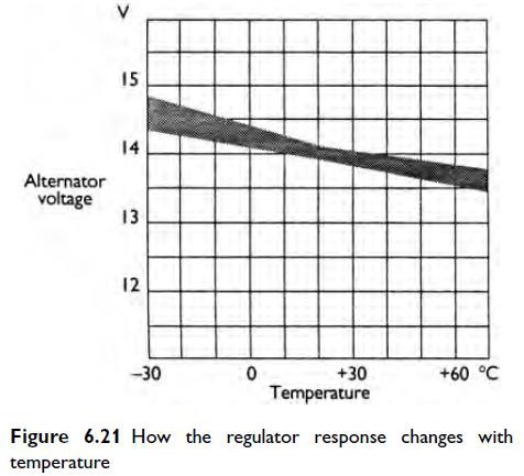
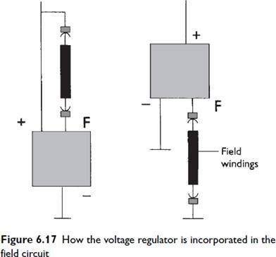
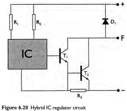
When working with regulator circuits, care must be taken to note ‘where’ the field circuit is interrupted. For example, some alternator circuits supply a constant feed to the field windings from the excitation diodes and the regulator switches the earth side. In other systems, one side of the field windings is will switch off, allowing T2 to switch back on and so the cycle will continue. The conventional diode, D1, absorbs the back EMF from the field windings and so prevents damage to the other components. Electronic regulators can be made to sense either the battery voltage, the machine voltage (alternator), or a combination of the two. Most systems in use at present tend to be machine sensed as this offers some protection against over-voltage in the event of the alternator being driven with the battery disconnected. Figure 6.20 shows the circuit of a hybrid integrated circuit (IC) voltage regulator. The hybrid system involves the connection of discrete components on a ceramic plate using film techniques. The main part of the regulator is an integrated circuit containing the sensing elements and temperature compensation components. The IC controls an output stage such as a Darlington pair. This technique produces a very compact device and, because of the low number of components and connections, is very reliable. Figure 6.21 is a graph showing how the IC regulator response changes with temperature. This change is important to ensure correct charging under ‘summer’ and ‘winter’ conditions. When a battery is cold, the electrolyte resistance increases. This means a higher voltage is necessary to cause the correct recharging current. Over-voltage protection is required in some applications in order to prevent damage to electronic components. When an alternator is connected to a vehicle battery system, the voltage, even in the event of regulator failure, will not often exceed about 20V due to the low resistance and swamping effect of the battery. If an alternator is run with the battery disconnected (which is not recommended), a heavy duty Zener diode connected across the output of the WL/field diodes will offer some protection as, if the system voltage exceeds its breakdown figure, it will conduct and cause the system voltage to be kept within reasonable limits.
For many applications, the charging circuit is one of the simplest on the vehicle. The main output is connected to the battery via a suitably sized cable (or in some cases two cables to increase reliability and flexibility), and the warning light is connected to an ignition supply on one side and to the alternator terminal at the other. A wire may also be connected to the phase terminal if it is utilized. Figure 6.22 shows two typical wiring circuits. Note that the output of the
alternator is often connected to the starter main supply simply for convenience of wiring. If the wires are kept as short as possible this will reduce voltage drop in the circuit. The voltage drop across the main supply wire when the alternator is producing full output current, should be less than 0.5V.
Some systems have an extra wire from the alternator to ‘sense’ battery voltage directly. An ignition feed may also be found and this is often used to ensure instant excitement of the field windings. A number of vehicles link a wire from the engine management ECU to the alternator. This is used to send a signal to increase engine idle speed if the battery is low on charge.
CUTOUT RELAY
The cutout relay (Figs. 2 & 3) has two windings, a series winding of a few turns of heavy wire (shown in solid red) and a shunt winding of many turns of fine wire (shown in dashed red). The shunt winding is connected across the generator so that generator voltage is impressed upon it at all times.
The series winding is connected in series with the charging circuit so that all generator output passes through it. The relay core and windings are assembled into a frame. A flat steel armature is attached to the frame by a flexible hinge so that it is centered just above the end of the core. The armature contact points are located just above the stationary contact points. When the generator is not operating, the armature contact points are held a wax from the stationary points by the tension of a flat spring riveted on the side of the armature.
CUTOUT RELAY ACTION-When the generator voltage builds up a value great enough to charge the battery, the magnetism induced by the relay windings is sufficient to pull the armature toward the core so that the contact points close. This com- pletes the circuit between the generator and battery. The current which flows from the generator to the battery passes through the series winding in a direction to add to the magnetism holding the armature down and the contact points closed.
When the' generator slows down or stops, current begins to flow from the battery to the generator. This reverse flow of current through the series winding causes a reversal of the series winding magnetic field. The magnetic field of the shunt winding does not reverse. Therefore, instead of helping each other, the two windings now magnetically oppose so that the resultant magnetic field becomes insufficient to hold the armature down. The flat spring pulls the armature away from the core so that the points separate; this opens the circuit between the generator and battery.
VOLTAGE REGULATOR
The voltage regulator (Figs. 2 & 3) has two windings assembled on a single core, a shunt winding consisting of many turns of fine wire (shown in dashed red) which is shunted across the generator, and a series winding of a few turns of relatively heavy wire (shown in solid blue) which is connected in series with the generator field circuit when the regulator contact points are closed.
The windings and core are assembled into a frame. A flat steel armature is attached to the frame by a flexible hinge so that it is just above the end of the core. The armature contains a contact point which is just beneath a stationary contact point. When the voltage regulator is not operating, the tension of a spiral spring holds the armature away from the core so that the points are in contact and the generator field circuit is completed to ground through them.
VOLTAGE REGULATOR ACTION-When the generator voltage reaches the value for which the voltage regulator is adjusted, the magnetic field produced by the two windings (shunt and series) overcomes the armature spring tension and pulls the armature down so that the contact points separate. This inserts resistance into the generator field circuit so that the generator field current and voltage are reduced. Reduction of the generator voltage reduces the magnetic field of the regulator shunt winding. Also, opening the regulator points opens the regulator series winding circuit so that its magnetic field collapses completely. The consequence is that the magnetic field is reduced sufficiently to allow the spiral spring to pull the armature away from the core so that the contact points again close. This directly grounds the generator field circuit so that generator voltage and output increase. The above cycle of action again takes place and the cycle continues at a rate of 50 to 200 times a second, regulating the voltage to a predetermined value. With the voltage thus limited the generator supplies varying amounts of current to meet the varying states of battery charge and electrical load.
A solenoid is simply a specially designed electromagnet. A solenoid usually consists of a cylindrical coil wound with one or more layers of insulated wire and a movable iron core called the armature. When current flows through a wire, a magnetic field is set up around the wire. If we make a coil of many turns of wire, this magnetic field becomes many times stronger, flowing around the coil and through its center in a doughnut shape. The length of the solenoid is much larger in comparison with its diameter. When the coil of the solenoid is energized with current, the core moves to increase the flux linkage by closing the air gap between the cores. The movable core is usually spring-loaded to allow the core to retract when the current is switched off. The force generated is approximately proportional to the square of the current and inversely proportional to the square of the length of the air gap.
Solenoids are inexpensive, and their use is primarily limited to on-off applications such as latching, locking, and triggering. They are frequently used in home appliances (e.g. washing machine valves), office equipment (e.g. copy machines), automobiles (e.g. door latches and the starter solenoid), pinball machines (e.g., plungers and bumpers), and factory automation.
Flux Distribution of a Solenoid
The direction of the field inside the solenoid may be found by applying the right hand rule for solenoids. This rule states that if a solenoid is grasped with the right hand such that the fingers point in the direction of the current in the wire, then the thumb will point in the direction of magnetic flux. The application of the right hand rule for solenoids is illustrated in figure 1.1. The flux distribution due to solenoid carrying current is given in figure 1.2. The magnetic field produced by a solenoid is similar to that of a bar magnet. One end of the solenoid becomes a north pole (N) where the flux leaves the solenoid. The other end becomes the South Pole (S) where the flux enters it.
Figure 1.1 Right hand rule for solenoid
Figure 1.2 Magnetic field due to a solenoid carrying current
Application of Solenoid
An electromechanical relay is a solenoid used to make or break mechanical contact between electrical leads. A small voltage input to the solenoid controls a potentially large current through the relay contacts. Applications include power switches and electromechanical control elements. A relay performs a function similar to a power transistor but has the capability to switch extremely large currents if necessary. However, transistors have a much shorter switching time than relays.
As illustrated in figure 2, a voice coil consists of a coil that moves in a magnetic field produced by a permanent magnet and intensified by an iron core. The force on the coil is directly proportional to the current in the coil. The coil is usually attached to a movable load such as the diaphragm of an audio speaker, the spool of a hydraulic proportional valve, or the read-write head of a computer disk drive. The linear response and bidirectional capability make voice coils more attractive than solenoids for control applications.
The Charging system is an important part of the electrical system. The charging system has two essential functions:
Electrical Power: At low engine speeds, the battery may supply some of the power the vehicle needs. At high engine speeds, the charging system handles all of the vehicle’s electrical requirements.
Charging: Alternator (generator) output is higher than battery voltage to recharge the battery. The charging system components:
These components make up the charging system:
The alternator generates electrical power to run accessories and to recharge the batteries. It is normally driven by a belt located off the crankshaft. Mechanical energy from the crankshaft is converted by the alternator into electrical energy for the batteries and accessories.
The alternator contains three main components:
Slip ring and brushes make an electrical connection to the spinning rotor. The alternator generates electricity through these steps:
The voltage regulator acts as an electrical traffic cop to control alternator output. It senses when the batteries need recharging, or when the vehicles electrical needs increase, and adjusts the alternators output accordingly. ie., it controls the alternator’s output current to prevent over- charging and under charging of the battery. It does this by regulating the current flowing from the battery to the rotor’s field coil.
The voltage regulator can be mounted inside or outside of the alternator housing. If the regulator is mounted outside there will be a wiring harness connecting it to the alternator. Today’s IC voltage regulator is a fully electronic device, using resistors and diodes.
The batteries are a reservoir of chemical electrical power. Their primary purpose is to crank the engine. They also supply power to vehicle accessories when the electrical load is too great for the alternator alone. The battery also acts as a voltage stabilizer. The battery must always remain attached to the electrical system while the engine is running.
The charging indicator is usually an ON /OFF warning lamp. When the system is running, the light should be off. The lamp lights when the charging system is not providing sufficient charge.
AC generators are usually called alternators. They are also called synchronous generators. A synchronous generator is a machine for converting mechanical power from a prime mover to ac electric power at a specific voltage and frequency.
Principle of Operation: The operation of a synchronous generator is based on Faraday's law of electromagnetic induction, and in an ac synchronous generator the generation of emf's is by relative motion of conductors and magnetic flux. The rotating magnetic field induces an AC voltage in the stator windings. Since the currents in the stator windings vary in step with the position of the rotor, an alternator is a synchronous generator.
In constructing a synchronous machine a point to note is that the stator is fixed and the poles rotate.
There are two categories of Synchronous machines:
4-Pole Salient Rotor A Salient Pole Rotor
2-pole Cylindrical Rotor A Cylindrical Rotor
Single Phase Alternator
Three Phase Alternator
Three Phase Stator Connection
Three Phase STAR Connected
Three Phase DELTA Connected
where N is the speed of the rotor in revolutions per minute,
P is the number of poles
f is the electrical line frequency produced by the alternator.
Source: http://fmcet.in/AUTO/AT6502_uw.pdf
Web site to visit: http://fmcet.in
Author of the text: indicated on the source document of the above text
If you are the author of the text above and you not agree to share your knowledge for teaching, research, scholarship (for fair use as indicated in the United States copyrigh low) please send us an e-mail and we will remove your text quickly. Fair use is a limitation and exception to the exclusive right granted by copyright law to the author of a creative work. In United States copyright law, fair use is a doctrine that permits limited use of copyrighted material without acquiring permission from the rights holders. Examples of fair use include commentary, search engines, criticism, news reporting, research, teaching, library archiving and scholarship. It provides for the legal, unlicensed citation or incorporation of copyrighted material in another author's work under a four-factor balancing test. (source: http://en.wikipedia.org/wiki/Fair_use)
The information of medicine and health contained in the site are of a general nature and purpose which is purely informative and for this reason may not replace in any case, the council of a doctor or a qualified entity legally to the profession.
The texts are the property of their respective authors and we thank them for giving us the opportunity to share for free to students, teachers and users of the Web their texts will used only for illustrative educational and scientific purposes only.
All the information in our site are given for nonprofit educational purposes