
The Otto cycle, which was first proposed by a Frenchman, Beau de Rochas in 1862, was first used on an engine built by a German, Nicholas A. Otto, in 1876. The cycle is also called a constant volume or explosion cycle. This is the equivalent air cycle for reciprocating piston engines using spark ignition. Figures 1 and 2 show the P-V and T-s diagrams respectively.
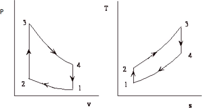
Fig.1: P-V Diagram of Otto Cycle. Fig.2: T-S Diagram of Otto Cycle.
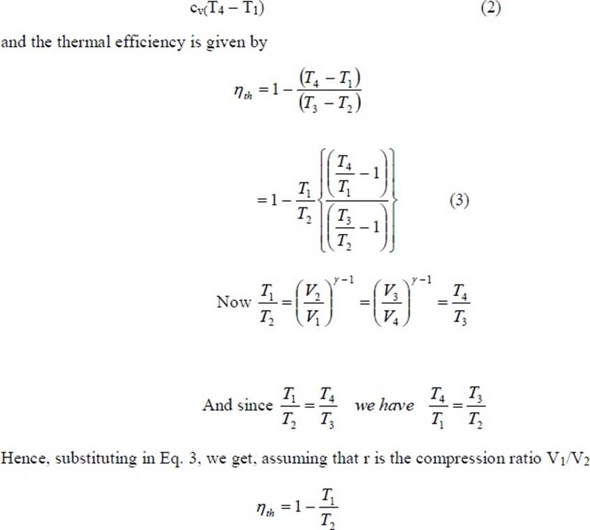
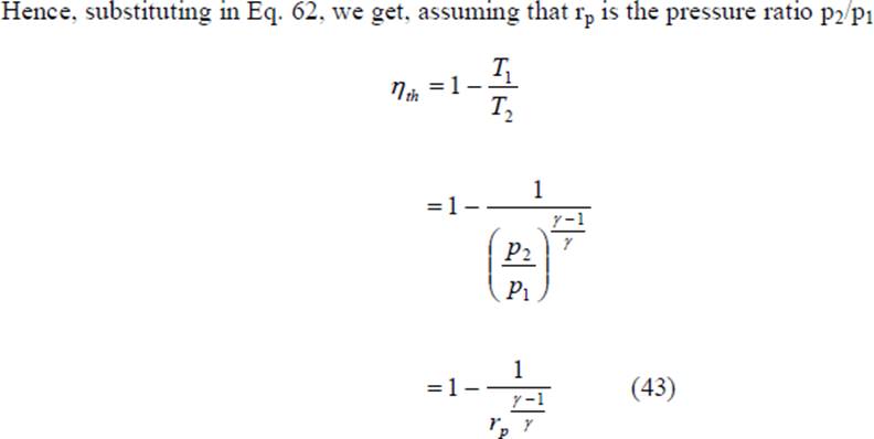
At the start of the cycle, the cylinder contains a mass M of air at the pressure and volume indicated at point 1. The piston is at its lowest position. It moves upward and the gas is compressed isentropically to point 2. At this point, heat is added at constant volume which raises the pressure to point 3. The high pressure charge now expands isentropically, pushing the piston down on its expansion stroke to point 4 where the charge rejects heat at constant volume to the initial state, point 1. The isothermal heat addition and rejection of the Carnot cycle are replaced by the constant volume processes which are, theoretically more plausible, although in practice, even these processes are not practicable. The heat supplied, Qs, per unit mass of charge, is given by
![]()
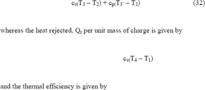
the heat rejected, Qr per unit mass of charge is given by
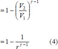
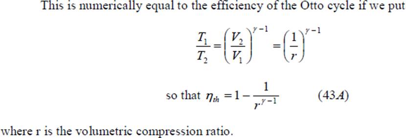
In a true thermodynamic cycle, the term expansion ratio and compression ratio are synonymous. However, in a real engine, these two ratios need not be equal because of the valve timing and therefore the term expansion ratio is preferred sometimes. Equation 4 shows that the thermal efficiency of the theoretical Otto cycle increases with increase in compression ratio and specific heat ratio but is independent of the heat added (independent of load) and initial conditions of pressure, volume and temperature. Figure 3 shows a plot of thermal efficiency versus compression ratio for an Otto cycle. It is seen that the increase in efficiency is significant at lower compression ratios. This is also seen in Table 1 given below.
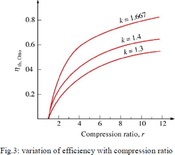
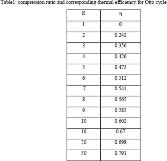
From the table it is seen that if: CR is increased from 2 to 4, efficiency increase is 76% CR is increased from 4 to 8, efficiency increase is only 32.6% CR is increased from 8 to 16, efficiency increase is only 18.6%.
It is seen that the air standard efficiency of the Otto cycle depends only on the compression ratio. However, the pressures and temperatures at the various points in the cycle and the net work done, all
depend upon the initial pressure and temperature and the heat input from point 2 to point 3, besides the compression ratio.
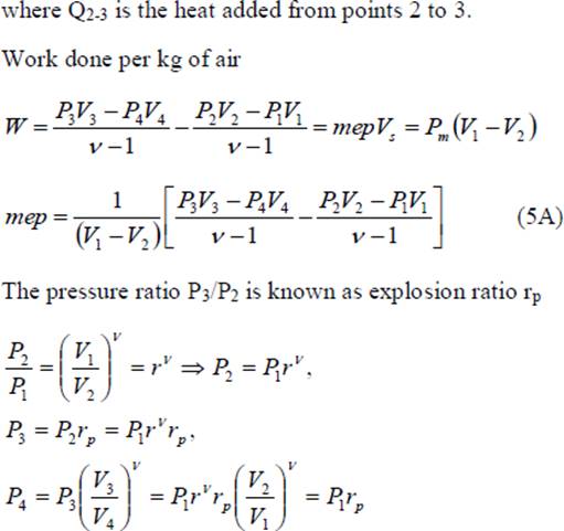
A quantity of special interest in reciprocating engine analysis is the mean effective pressure. Mathematically, it is the net work done on the piston, W, divided by the piston displacement volume, V1 – V2. This quantity has the units of pressure. Physically, it is that constant pressure which, if exerted on the piston for the whole outward stroke, would yield work equal to the work of the cycle. It is given by
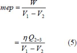
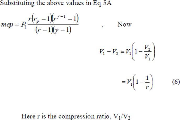
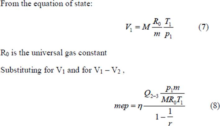
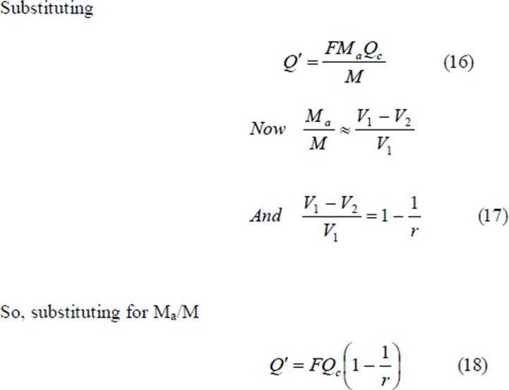
The quantity Q2-3/M is the heat added between points 2 and 3 per unit mass of air (M is the mass of air and m is the molecular weight of air); and is denoted by Q‟, thus
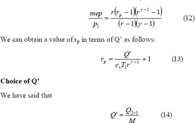
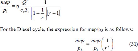
We can non-dimensionalize the mep by dividing it by p1 so that we can obtain the following equation
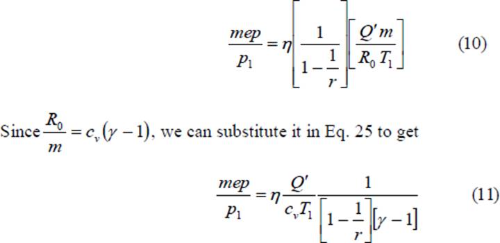
The dimensionless quantity mep/p1 is a function of the heat added, initial temperature, compression ratio and the properties of air, namely, cv and γ. We see that the mean effective pressure is directly proportional to the heat added and inversely proportional to the initial (or ambient) temperature. We can substitute the value of η from Eq. 8 in Eq. 14 and obtain the value of mep/p1 for the Otto cycle in terms of the compression ratio and heat added. In terms of the pressure ratio, p3/p2 denoted by rp we could obtain the value of mep/p1 as follows:
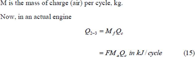
Mf is the mass of fuel supplied per cycle, kg Qc is the heating value of the fuel, Kj/kg Ma is the mass of air taken in per cycle F is the fuel air ratio = Mf/Ma
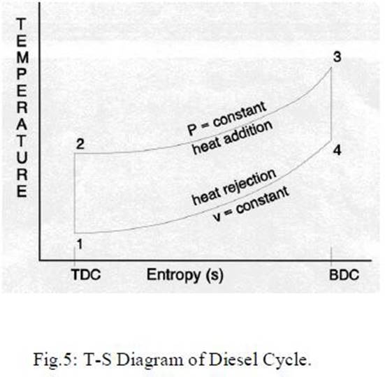
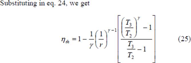
Diesel Cycle This cycle, proposed by a German engineer, Dr. Rudolph Diesel to describe the processes of his engine, is also called the constant pressure cycle. This is believed to be the equivalent air cycle for the reciprocating slow speed compression ignition engine. The P-V and T-s diagrams are shown in Figs 4 and 5 respectively.
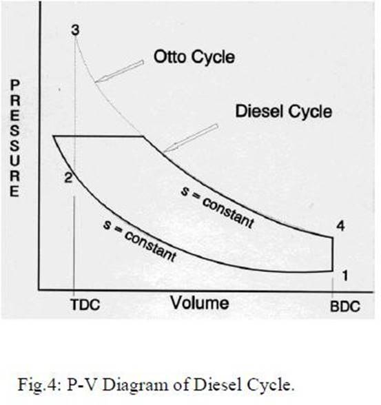
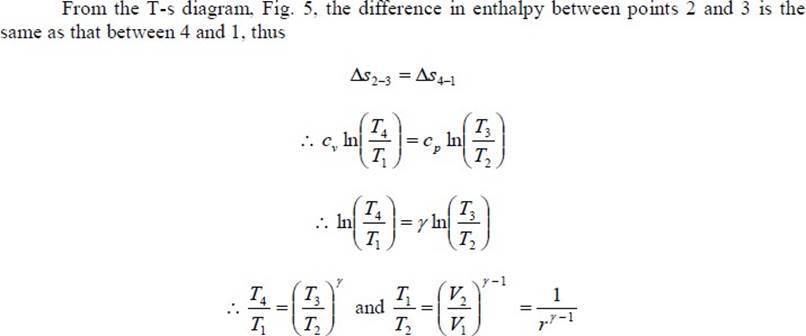
The cycle has processes which are the same as that of the Otto cycle except that the heat is added at constant pressure. The heat supplied, Qs is given by
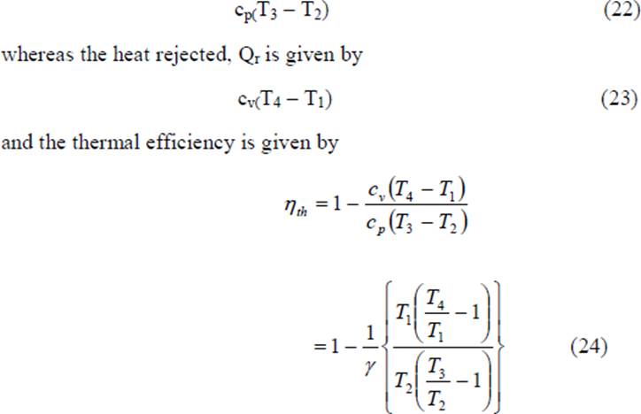
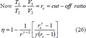
When Eq. 26 is compared with Eq. 8, it is seen that the expressions are similar except for the term in the parentheses for the Diesel cycle. It can be shown that this term is always greater than unity.
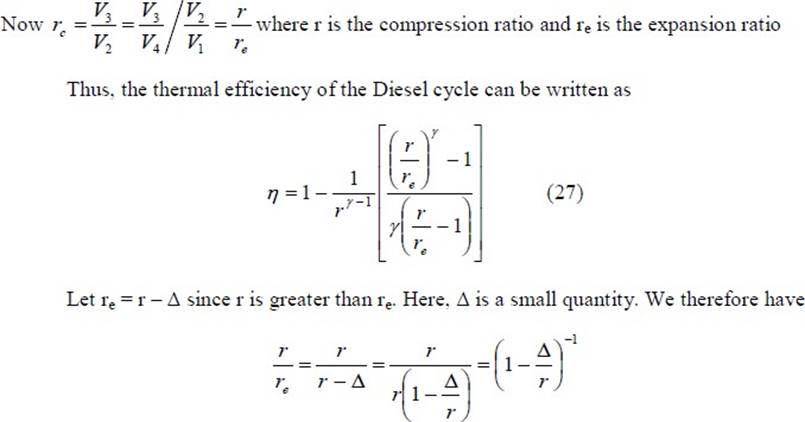
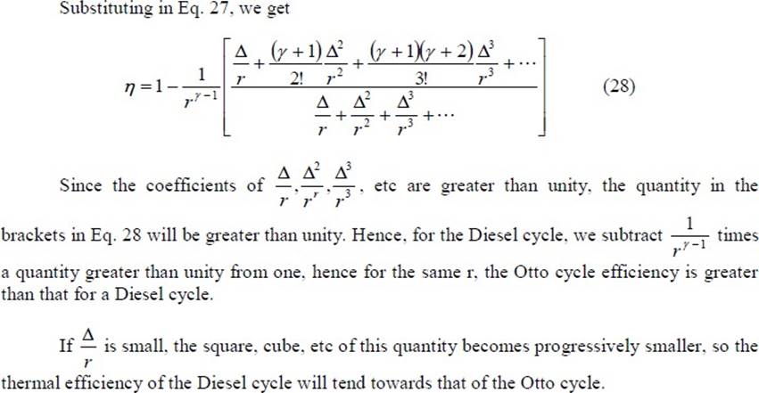
From the foregoing we can see the importance of cutting off the fuel supply early in the forward stroke, a condition which, because of the short time available and the high pressures involved, introduces practical difficulties with high speed engines and necessitates very rigid fuel injection gear. In practice, the diesel engine shows a better efficiency than the Otto cycle engine because the compression of air alone in the former allows a greater compression ratio to be employed. With a mixture of fuel and air, as in practical Otto cycle engines, the maximum temperature developed by compression must not exceed the self ignition temperature of the mixture; hence a definite limit is imposed on the maximum value of the compression ratio. Thus Otto cycle engines have compression ratios in the range of 7 to 12 while diesel cycle engines have compression ratios in the range of 16 to 22.

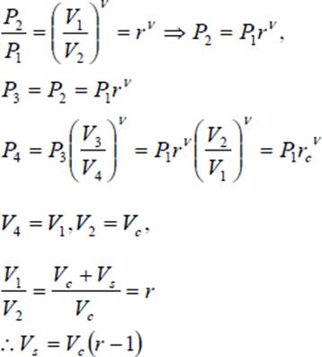
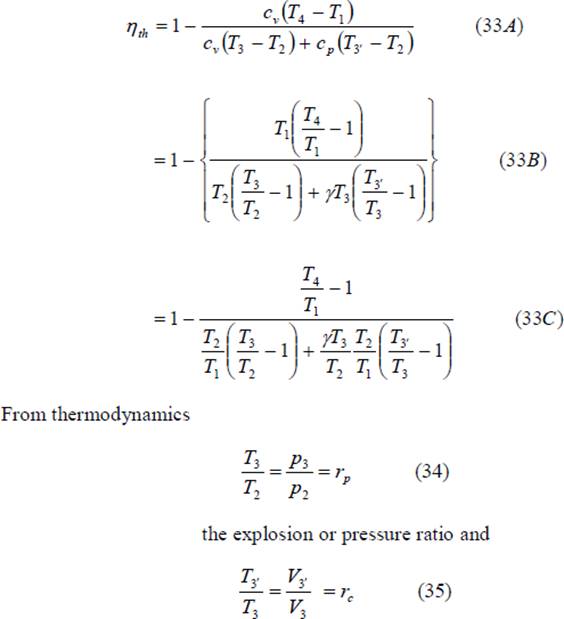
The pressure ratio P3/P2 is known as explosion ratio rp
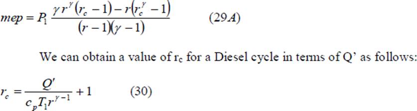
Substituting the above values in Eq 29 to get Eq (29A) In terms of the cut-off ratio, we can obtain another expression for mep/p1 as follows
We can substitute the value of η from Eq. 38 in Eq. 26, reproduced below and obtain the value of mep/p1 for the Diesel cycle.
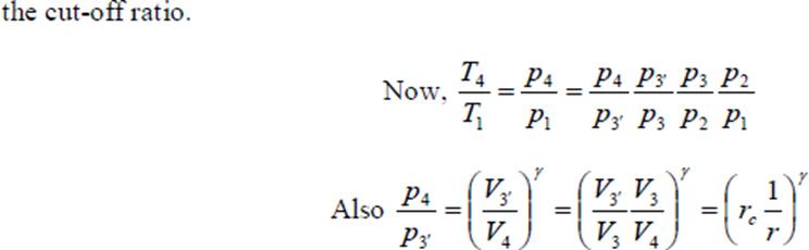
Modern high speed diesel engines do not follow the Diesel cycle. The process of heat addition is partly at constant volume and partly at constant pressure. This brings us to the dual cycle.
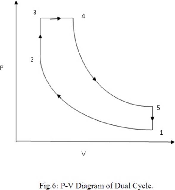
Process 1-2: Reversible adiabatic compression. Process 2-3: Constant volume heat addition. Process 3-4: Constant pressure heat addition. Process 4-5: Reversible adiabatic expansion. Process 5-1: Constant volume heat reject
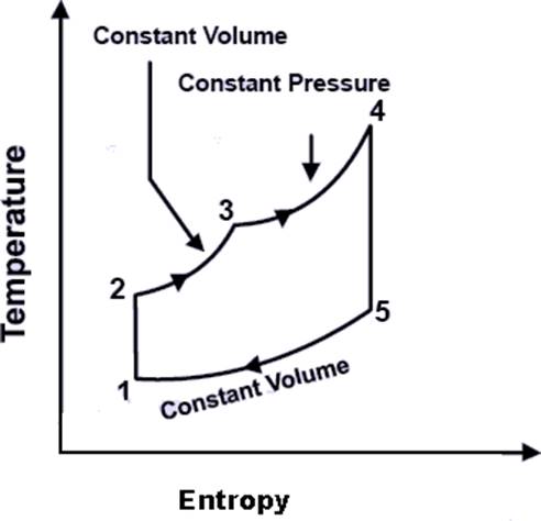
The cycle is the equivalent air cycle for reciprocating high speed compression ignition engines. The P-V and T-s diagrams are shown in Figs.6 and 7. In the cycle, compression and expansion processes are isentropic; heat addition is partly at constant volume and partly at constant pressure while heat rejection is at constant volume as in the case of the Otto and Diesel cycles. The heat supplied, Qs per unit mass of charge is given by
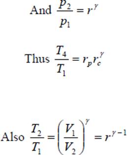
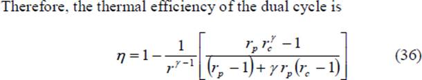
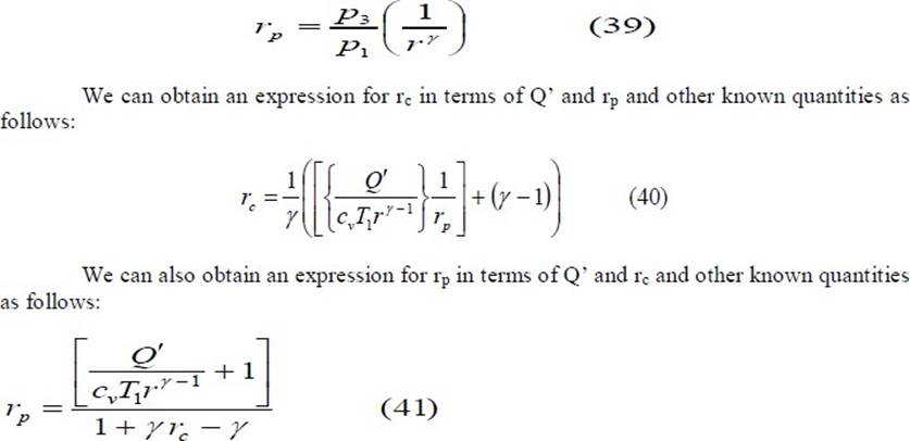
We can substitute the value of η from Eq. 36 in Eq. 14 and obtain the value of mep/p1 for the dual cycle. In terms of the cut-off ratio and pressure ratio, we can obtain another expression for mep/p1 as follows:
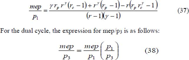
Since the dual cycle is also called the limited pressure cycle, the peak pressure, p3, is usually specified. Since the initial pressure, p1, is known, the ratio p3/p1 is known. We can correlate rp with this ratio as follows:
The Brayton cycle is also referred to as the Joule cycle or the gas turbine air cycle because all modern gas turbines work on this cycle. However, if the Brayton cycle is to be used for reciprocating piston engines, it requires two cylinders, one for compression and the other for expansion. Heat addition may be carried out separately in a heat exchanger or within the expander itself.
The pressure-volume and the corresponding temperature-entropy diagrams are shown in Figs 10 and 11 respectively.
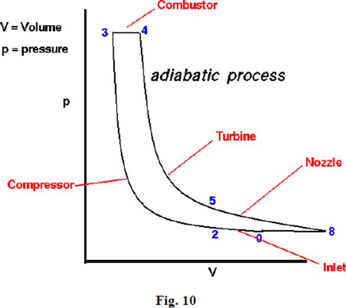
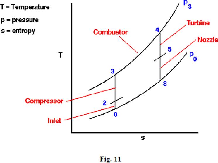
The cycle consists of an isentropic compression process, a constant pressure heat addition process, an isentropic expansion process and a constant pressure heat rejection process. Expansion is carried out till the pressure
drops to the initial (atmospheric) value. Heat supplied in the cycle, Qs, is given by Cp(T3 – T2) Heat rejected in the cycle, Qs, is given by
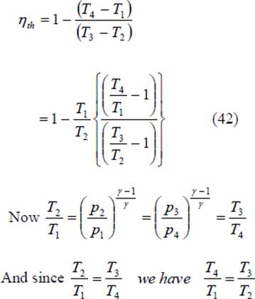
Cp(T4 – T1) Hence the thermal efficiency of the cycle is given by
temperature 30Oc, at the beginning of compression stroke. At the end of Compression stroke, the pressure is 11 bar and 210 KJ of heat is added at constant Volume. Determine
Source: http://fmcet.in/MECH/ME6404_uw.pdf
Web site to visit: http://fmcet.in
Author of the text: indicated on the source document of the above text
If you are the author of the text above and you not agree to share your knowledge for teaching, research, scholarship (for fair use as indicated in the United States copyrigh low) please send us an e-mail and we will remove your text quickly. Fair use is a limitation and exception to the exclusive right granted by copyright law to the author of a creative work. In United States copyright law, fair use is a doctrine that permits limited use of copyrighted material without acquiring permission from the rights holders. Examples of fair use include commentary, search engines, criticism, news reporting, research, teaching, library archiving and scholarship. It provides for the legal, unlicensed citation or incorporation of copyrighted material in another author's work under a four-factor balancing test. (source: http://en.wikipedia.org/wiki/Fair_use)
The information of medicine and health contained in the site are of a general nature and purpose which is purely informative and for this reason may not replace in any case, the council of a doctor or a qualified entity legally to the profession.
The texts are the property of their respective authors and we thank them for giving us the opportunity to share for free to students, teachers and users of the Web their texts will used only for illustrative educational and scientific purposes only.
All the information in our site are given for nonprofit educational purposes