
![]() ,
,
![]()
![]()
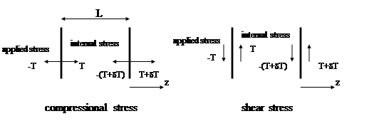
![]() (compressional).
(compressional).
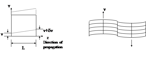
The parameter S is defined as strain, it represents the fractional extension of the material. Longitudinal motion changes the cube volume by dw*A, where A is the area of the cross section. Therefore, the relative change in volume is dw/L = S since the total volume of A*L.
![]() (shear) .
(shear) .
Note that there is no change in area (volume) and density as shear motion distorts it.
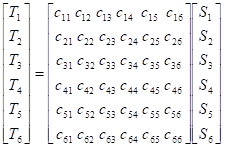
T=cS,
where c is the elastic constant of the material.
Tensor notation |
Reduced notation |
xx |
1 |
yy |
2 |
zz |
3 |
yz=zy |
4 |
zx=xz |
5 |
xy=yx |
6 |
 .
.
 .
.
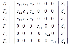
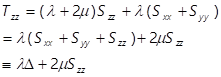
In addition,
![]() .
.
The above equation holds because when a material is compressed in one direction, it tends to expand in a perpendicular direction for an isotropic material and small displacements. Thus, only two independent elastic constants are needed for an isotropic medium. These two parameters are also known as the Lamé constants ![]() and
and ![]() . Note that
. Note that ![]() is the ratio of the longitudinal stress in the z direction to the longitudinal strain in the y direction. m is also called the shear modulus (or modulus of rigidity).
is the ratio of the longitudinal stress in the z direction to the longitudinal strain in the y direction. m is also called the shear modulus (or modulus of rigidity).
 ,
,
where D is defined as dilation, representing the fractional change in volume.
Since shear stresses are not supported in fluids, by setting Txx and Tyy to be zeros, we can obtain the Young’s modulus (E):
![]() .
.
![]() ,
,
where
![]() .
.
It is then straightforward to see that
![]()
![]()
![]() ,
,
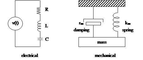
the motion equation for the mechanical system is (based on Newton’s second law)
![]() ,
,
where the analogies are
Electrical |
Mechanical |
||
q |
charge |
w |
displacement |
i=dq/dt |
current |
U=dw/dt |
particle velocity |
V |
voltage |
f |
force (stress, pressure) |
L |
inductance |
m |
mass |
1/C |
1/capacitance |
km |
stiffness |
R |
resistance |
rm |
damping |
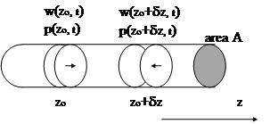
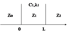
In the above figure, w(z,t) is displacement and p(z,t) is pressure. Therefore,
![]()
![]()
where r is the density. By taking dz ® 0 and using Bulk modulus (B), we have
![]()
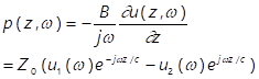
By taking Fourier transform of the above equation (with respect to time) we have a general solution of the wave equation (in temporal frequency domain)
![]()
where ![]() is the propagation speed of the particle displacement wave. In time domain, we have
is the propagation speed of the particle displacement wave. In time domain, we have
![]()
In other words, the first term represents a wave traveling to the right and the second to the left.
Since the particle velocity u(z,t) is defined as ![]() , in the temporal frequency domain we have
, in the temporal frequency domain we have
![]()
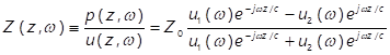
It is then straightforward to see that
where ![]() and is called the characteristic impedance of the medium. Note the analogy between pressure, particle velocity and voltage, current.
and is called the characteristic impedance of the medium. Note the analogy between pressure, particle velocity and voltage, current.
If there is only propagation to the right (or left), then the above equation can be reduced to ![]() ( or
( or ![]() ).
).
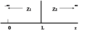
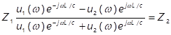
since both pressure and particle velocity are continuous functions and medium 2 is infinite to the right, we have ![]() , i.e.,
, i.e.,
![]()
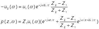
At the boundary (i.e., z=L), we have
![]()
![]()
Since medium 2 is infinite to the right, the above equation is also the pressure wave in medium 2.
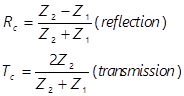
Since the normal components of the particle velocity at the boundary must be continuous, then ![]() . Additionally, since the pressure is also continuous at the boundary (i.e.,
. Additionally, since the pressure is also continuous at the boundary (i.e., ![]() ), it is then straightforward to obtain the following relations
), it is then straightforward to obtain the following relations
![]()
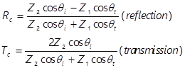
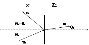
Note that at normal incidence, the above equations reduce to the 1D equations.
![]()
where c1 and c2 are the propagation velocities in medium 1 and 2, respectively. If c1 > c2 , a critical angle ![]() can be defined as
can be defined as ![]() . For any incidence angle greater than the critical angle, total reflection occurs ( i.e., there is no transmission).
. For any incidence angle greater than the critical angle, total reflection occurs ( i.e., there is no transmission).
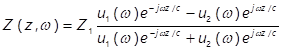
In general, impedance in medium 1 (Z(z,w)) is a complex value
![]()
To avoid reflection at boundaries, we need to have

Combining the above equations, we have
![]()
where ![]() . Note that by choosing
. Note that by choosing
![]() for n=0,1,2,…
for n=0,1,2,…
Zo is real and ![]() . Normally, n is chosen to be 0 and this is called “quarter wavelength impedance matching”. Note that if
. Normally, n is chosen to be 0 and this is called “quarter wavelength impedance matching”. Note that if ![]() , then
, then ![]() and this is a trivial case of no discontinuities. Also note that for multiple layers, impedance values can be found by iterations.
and this is a trivial case of no discontinuities. Also note that for multiple layers, impedance values can be found by iterations.
- Pa (Pascal, pressure) : ![]()
- Rayl (acoustic impedance) : ![]()
Source: http://home.ee.ntu.edu.tw/classnotes/us1/chapter2.doc
Web site to visit: http://home.ee.ntu.edu.tw
Author of the text: indicated on the source document of the above text
If you are the author of the text above and you not agree to share your knowledge for teaching, research, scholarship (for fair use as indicated in the United States copyrigh low) please send us an e-mail and we will remove your text quickly. Fair use is a limitation and exception to the exclusive right granted by copyright law to the author of a creative work. In United States copyright law, fair use is a doctrine that permits limited use of copyrighted material without acquiring permission from the rights holders. Examples of fair use include commentary, search engines, criticism, news reporting, research, teaching, library archiving and scholarship. It provides for the legal, unlicensed citation or incorporation of copyrighted material in another author's work under a four-factor balancing test. (source: http://en.wikipedia.org/wiki/Fair_use)
The information of medicine and health contained in the site are of a general nature and purpose which is purely informative and for this reason may not replace in any case, the council of a doctor or a qualified entity legally to the profession.
The texts are the property of their respective authors and we thank them for giving us the opportunity to share for free to students, teachers and users of the Web their texts will used only for illustrative educational and scientific purposes only.
All the information in our site are given for nonprofit educational purposes