
The microcontroller can only process digital (high/low) signals. However in many practical applications analogue quantities, such as light intensity or temperature, need to be tested.
An Analogue-to-Digital Converter (ADC) is a device which can convert analogue quantities into digital signals. An 8-bit ADC can generate a digital signal in the range 0 to 255 (i.e. one byte). ADC's are available as separate integrated circuits, or may even be 'built into' the microcontroller to give it 'on-board' ADC capabilities. With the Stamp Controller system an external 8-bit ADC integrated circuit is used.
ADCs are designed to process analogue signals within a certain range. The maximum voltage signal that can be processed by an ADC is called its reference voltage. A common reference voltage for an 8-bit ADC is 2.55V, so the ADC can measure signals in the range 0 to 2.55V. Therefore the 8-bit ADC device will generate an 8-bit value directly equivalent to the voltage signal applied.
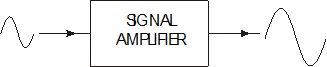
Analogue sensors, such as the thermistor (temperature sensor), may not directly produce a suitable signal for use with the ADC. Therefore it is often necessary to use a signal amplifier circuit so that the input signal can be 'conditioned' to the input range of the ADC (0 to 2.5V). An operational amplifier, configured as a voltage amplifier, is commonly used for this task. The following example shows how the gain of the operational circuit is typically calculated.
Example:
A temperature sensor is to be used to monitor the temperature of a factory furnace.
Experimentation has shown that the temperature sensor produces a linear output signal, reading 0V at 0º Celsius and 1.53V at a temperature of 200º Celsius. The maximum operating temperature of the furnace is 1000º Celsius. The maximum voltage that may be fed into the ADC is 2.55V
Draw a circuit diagram of a suitable signal conditioning system based on operational amplifiers.
Solution:
1) Calculate the maximum input signal, which is at 1000º Celsius.
Signal at 200º = 1.53V
1000º is equal to 5 x 200º
Therefore maximum signal is 5 x 1.53V = 7.65V
2) Calculate the gain required from the op-amp circuit.
Input Signal = 7.65V
Required output signal = 2.55V
Therefore Gain = output / input = 2.55 / 7.65 = 0.33
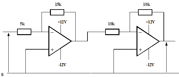
3) Draw circuit diagram of a voltage amplifier circuit with gain set to 0.33
![]()
Inverting Amp Inverting Amp
Multiplexers
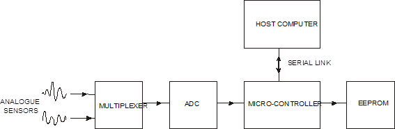
ADC integrated circuits are relatively expensive to construct. When it is necessary to record more than one analogue signal a 'multiplexer' can be used to prevent the need for multiple ADC circuits. The multiplexer can be physically 'built into' the ADC integrated circuit, or can be provided by a completely separate integrated circuit.
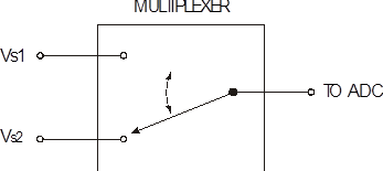
The multiplexer functions in a similar manner to a rotary switch connecting each of the analogue channels in turn to the ADC. Therefore the multiplexer 'selects' which sensor is connected to the ADC at any one time. As only one sensor is connected to the ADC at any one time the whole system is slower than using a separate ADC for each sensor. However modern microcontrollers operate very quickly, and so the cost saving usually outweighs the increased processing time.
Data loggers are used in a wide range of applications from flight recorders on aircraft to life support systems in incubators for premature babies.
The frequency at which signals are recorded is called the sample frequency. A high frequency rate would be used to record a very fast changing signal over a small period of time - for instance when measuring the electrical activity of the human heart. A low frequency rate would be used when a slow changing signal is measured over a long period of time - for instance monitoring the temperature of a green house over a week period.
As data loggers are generally small, portable and battery operated, the data is often stored electronically in EEPROM integrated circuits. This means the data is retained when the batteries are removed, but can also be updated easily when required. Data loggers can be left unattended for long periods of time, and are ideal for hostile or remote environments measuring variations in industrial and weather monitoring situations.
Once a data logging experiment is complete, it is obviously necessary to be able to retrieve the data for analysis. In more basic systems the data may just be printed out directly as a simple table, but in more advanced systems it is common to 'upload' the data to a personal computer for mathematical analysis and/or graph generation in a spreadsheet application.
The Data Logger Module
The data logger module contains a 512 byte EEPROM integrated circuit. In practical terms this means that up to 512 8-bit ADC readings can be stored in the EEPROM.
The data logger module also contains the electronic connectors necessary to link a serial computer cable, so that the data stored in the EEPROM can be uploaded to a personal computer for analysis.
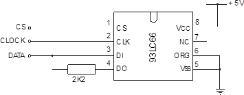
The EEPROM integrated circuit is a serial device, and operates in a very similar manner to the serial ADC, using the same three data, clock and chip select signals. However in this case the data signal is bi-directional, as it is necessary to write to, and read from, the EEPROM memory.
The 512 byte memory is divided into two pages, each page containing 256 bytes. Therefore to correctly locate a memory cell you must specify both its page number (0 or 1) and its address (0 to 255).
Like the ADC, the EEPROM makes use of two 'standard' sub-procedures to carry out the serial communication. These sub-procedures can be copied directly from the datasheets. Sub-procedure 'eewrite' is used to write data to the EEPROM, and 'eeread' is used to read data back from the EEPROM.
Therefore to write the value '85' to EEPROM address '23' on page '1' the program would be
let data = 85 'Set the data.
let address = 23 'Set the address.
let page = 1 'Set the page.
gosub eewrite 'Write the data to the EEPROM.
To retrieve the data and show it on the computer screen (via the debug command) the program would be
let address = 23 'Set the address.
let page = 1 'Set the page.
gosub eeread 'Read the data from the EEPROM.
debug data 'Send data to the computer screen.
Analysing Data with a Spread-sheet
After a data-logging experiment it is usual to 'upload' the data to a host computer so that the readings can be analysed via a spread-sheet application. This enables mathematical calculations to be made, and also allows the generation of graphs.
The 'upload' procedure requires serial communication between the Stamp Controller and the host computer. This is achieved via a serial cable connected to the Datalogger Module
Source: http://www.earlstonhigh.scotborders.sch.uk/learningzone/technical/Revision%20Notes/HTS%20Revision%20notes/2-4%20Course%20notes.doc
Web site to visit: http://www.earlstonhigh.scotborders.sch.uk
Author of the text: indicated on the source document of the above text
If you are the author of the text above and you not agree to share your knowledge for teaching, research, scholarship (for fair use as indicated in the United States copyrigh low) please send us an e-mail and we will remove your text quickly. Fair use is a limitation and exception to the exclusive right granted by copyright law to the author of a creative work. In United States copyright law, fair use is a doctrine that permits limited use of copyrighted material without acquiring permission from the rights holders. Examples of fair use include commentary, search engines, criticism, news reporting, research, teaching, library archiving and scholarship. It provides for the legal, unlicensed citation or incorporation of copyrighted material in another author's work under a four-factor balancing test. (source: http://en.wikipedia.org/wiki/Fair_use)
The information of medicine and health contained in the site are of a general nature and purpose which is purely informative and for this reason may not replace in any case, the council of a doctor or a qualified entity legally to the profession.
The texts are the property of their respective authors and we thank them for giving us the opportunity to share for free to students, teachers and users of the Web their texts will used only for illustrative educational and scientific purposes only.
All the information in our site are given for nonprofit educational purposes