
Unit Process Life Cycle Inventory
Dr. Devi Kalla, Dr. Janet Twomey, and Dr. Michael Overcash
Boring is a unit process in manufacturing as a mass reduction step, used for enlarging and accurately sized existing hole by means of single point cutting tool. Boring is used to achieve greater accuracy of the diameter of a hole, and can be used to cut a tapered hole. Boring is a special case of turning in which the major motion of the cutting tool is at parallel to the axis of rotation of the rotating workpiece applied to internal surfaces of revolution. Hence this life cycle heuristic is to establish representative estimates of the energy and mass loss from the boring unit process in the context of manufacturing operations for products. The boring unit process life cycle inventory (uplci) profile is for a high production manufacturing operation, defined as the use of processes that generally have high automation and are at the low to medium throughput production compared to all other machines that perform a similar operation. This is consistent with the life cycle goal of estimating energy use and mass losses representative of efficient product manufacturing.
Boring usually requires that the workpiece be held in the chuck and rotated. As the workpiece is rotated, a boring bar with an insert attached to the tip of the bar is fed into an existing hole typically aided by cutting fluids. When the cutting tool engages the workpiece, a chip is formed. Depending on the type of tool used, the material, and the feed rate, the chip may be continuous or segmented. The boring process is used to produce cylindrical internal surfaces. Consequently, chip disposal in boring and the effectiveness of cutting fluids are important. Boring operations on relatively small workpieces can be carried out on CNC lathes; large workpieces are machined on boring mills. However, drill presses, machining centers and similar machines can be used as well. An example CNC machine is given in Figure MR8.1, while the boring mechanism is illustrated in Figure MR8.2. The cutting tools are similar to those used in turning and are mounted in a boring bar (Figure MR8.2) to reach the full length of the bore.
Figure MR8.3 shows an overview of the developed environmental-based factors for boring operations. For a given workpiece (illustrated in Figure MR8.2) the life cycle analysis yields energy use and mass losses as byproducts or wastes.
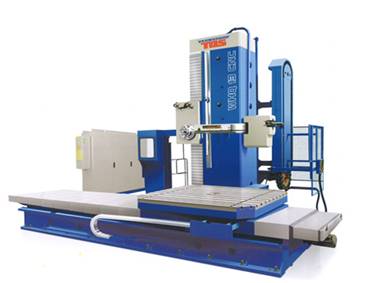
Figure MR8.1. Computer numerical control (CNC) boring machine with 3-axis control (Photograph from TOS Varnsdorf, Inc. Czech Republic)
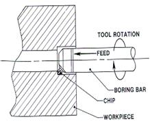
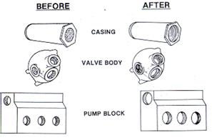
Figure MR8.2. Boring Process Schematic (Todd et al., 1994)
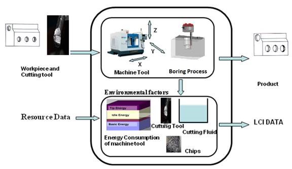
Figure MR8.3. LCI data for boring process
In order to assess a manufacturing process efficiently in terms of environmental impact, the concept of a unit operation is applied. The unit process consists of the inputs, process, and outputs of an operation. Each unit process is converting material/chemical inputs into a transformed material/chemical output. The unit process diagram of a boring process is shown Figure MR8.4.
The transformation of input to output in this report generates five lci characteristics,
Because high production boring is a semi-continuous process. Many of these automated CNC machines have more than three axes. One of the axes is often designed as a rotary table to position the work-piece at some specified angle relative to the spindle. The rotary table permits the cutter to perform boring on four sides of the part. These machines are classified as horizontal, vertical or universal based on the spindle orientation. The uplci is based on a representative operational sequence, in which
In this representative unit process, the life cycle characteristics can be determined on a per bored hole basis or on a full piece (with one or more holes) basis. Since this is a high production process, the startup (at the beginning of a batch or shift) is deemed to be small and not included. In this uplci, there are three typical power levels that will be used, Figure MR8.5. Correspondingly, there are times within the boring sequence from which these three power levels are used, Figure MR8.5. The overall time per piece is referred to as cycle time and is generally consistent in a batch. Each power level (basic, idle, and boring) is a reflection of the use of various components or sub-operations, of the CNC machine, Figure MR8.6. The steps 2), 3), 5), and 6) are estimated as representative values for use in this unit process lci and energy required of removing material by boring, step 4), is measured using specific cutting energy values.
The system boundaries are set to include only the use phase of the machine tool, disregarding production, maintenance and disposal of the machine. Moreover, the functioning of the manufacturing machines is isolated, with the influence of the other elements of the manufacturing system, such as material handling systems, feeding robots, etc. are covered in other uplci reports.
The energy consumption of boring is calculated as follows:
Etotal = Pbasic * (tbasic ) + Pidle * (tidle) + Pboring * (tboring ) (1)
(Basic energy) (Idle energy) (Boring energy)
An approximate importance of the many variables in determining the boring energy requirements was used to rank parameters from most important to lower importance as follows:
From this parameter list, only the top 5 were selected for use in this unit process life cycle with the others having lower influence on energy. Energy required for the overall boring process is also highly dependent on the time taken for idle and basic operations.
Boring time (tboring) and power (Pboring) must be determined for the boring energy and are calculated from the more important parameters given above. The calculations are illustrated in Figure MR8.7. The cutting speed, V (m/min), is the peripheral speed of the workpiece past the cutting tool. The rotational speed of the spindle, N, (rev/min) (set on the machine), N = V/ (π*Df). Where V = cutting speed, mm/min and Df = Final diameter of the hole, mm. Feed, f (mm/rev), for boring is the distance that a tool advances into the workpiece during one revolution of the headstock spindle. V and f are estimated from the material properties, Table MR8.2 and Table MR8.3. The feed rate, fr (mm/min) is the rate at which the cutting tool and the workpiece move in relation to one another. The feed rate, fr (mm/min), is the product of f *N. The volume removal rate has been defined as the expected cut area multiplied by the rate at which the material is removed perpendicular to the area. For boring, the area removed is an annular ring of finished diameter Dfand initial diameter Di. Thus, the expected cut area is
![]() (Df2 -Di2)/4. The rate at which the tool is fed, fr (in unit distance per minute), is f * N. Therefore, the volume removal rate (VRR) for boring is:
(Df2 -Di2)/4. The rate at which the tool is fed, fr (in unit distance per minute), is f * N. Therefore, the volume removal rate (VRR) for boring is:
VRR = (![]() (Df2 -Di2)/4) * fr (mm3/min)
(Df2 -Di2)/4) * fr (mm3/min)
Difference between the final and initial diameter is the depth of cut. The actual boring time is the depth of the hole, divided by the feed rate, fr.
Time for boring tboring = (d)/f*N = d/fr = d /[f*(V/π*Df)] (2)
Where d = Depth of the hole to be cut, mm.
f – Feed, mm/rev.
N- Spindle speed, rpm
fr - feed rate, mm/min
V – cutting speed, m/min
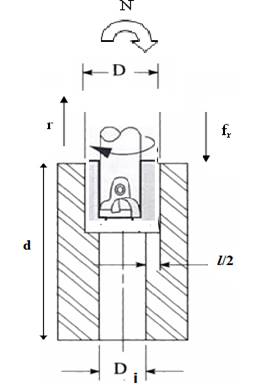
FigureMR8.7. Schematic Diagram of boring Process
The boring energy is thus E (Joule/hole) = Boring time*Pboring,
E = boring time*(volume removal rate)*(specific cutting energy, Up, W/mm3/sec)
Eboring (Joule/hole) = tboring *VRR*Up = tboring* Pboring (3)
With a given material to be cut, the specific cutting energy, Up, is given in Table MR8.2. Then for that material a representative cutting speed, V is selected from Table MR8.2. V and Df are used to calculate N. Then N and f are used to obtain fr.
The boring energy is then calculated from equation 3. Thus with only the material to be cut, and the depth of cut, one can calculate the lci boring energy for a single cut. This then must be added to the idle and basic energies, see below.
Table MR8.2 Average values of energy per unit material removal rate and recommended speeds and feeds ( Erik, 2000; Hoffman, 2001; Joseph, 1989; Kalpakjian, 2008; 9, 10)
Material |
Hardness |
Specific cutting energy, Up |
Cutting Speed, V (m/min, ft/min) |
Feed (f) |
Density (kg/m3) |
Low carbon alloy steels |
125 - 175 |
2.98 (1.1) |
24 - 46, 80 - 150 |
0.18 - 0.75, 0.007 - 0.030 |
7480-8000 |
Medium carbon alloy steels |
125 - 175 |
3.67 (1.35) |
11 - 43, 70 - 140 |
0.18 - 0.75, 0.007 - 0.030 |
7480-8000 |
High carbon alloy steels |
125 - 175 |
3.94 (1.45) |
18 - 54, 60 - 175 |
0.13 - 1.52, 0.005 - 0.06 |
7480-8000 |
Titanium Alloys |
250 - 375 |
3.26 (1.2) |
21 - 49, 70 - 160 |
0.13 - 1.27, 0.005 - 0.05 |
4500 |
Steels |
35 - 40 |
3.80 (1.4) |
12 - 18, 40 - 60 |
0.2, 0.007 |
7850 |
High temperature nickel and cobalt |
200-360 |
6.8 (2.5) |
56, 184 |
0.18, 0.007 |
8900 |
Aluminum alloys |
30 -150 |
0.68 (0.25) |
182 - 244, 600 - 800 |
0.18 - 0.64, 0.007 - 0.025 |
2712 |
Plain cast iron |
150 -175 |
0.82 (0.30) |
45 - 60, 148 - 196 |
0.5 - 0.89, 0.02 - 0.035 |
6800-7800 |
|
176 - 200 |
0.90 (0.33) |
35 - 50, 115 - 165 |
0.38 - 0.64, 0.015 - 0.025 |
6800-7800 |
|
201 - 250 |
1.14 (0.42) |
25 - 40, 82 - 132 |
0.3 - 0.56, 0.012 - 0.022 |
6800-7800 |
|
251 - 300 |
1.36 (0.50) |
18 - 32, 60 - 105 |
0.254 - 0.52, 0.010 - 0.020 |
6800-7800 |
Alloy cast iron |
150 - 175 |
0.82 (0.30) |
36 - 76, 120 - 250) |
0.38 - 0.64, 0.015 - 0.025 |
6800-7800 |
|
176 - 200 |
1.14 (0.42) |
24 - 46, 80 - 150 |
0.3 - 0.56, 0.012 - 0.022 |
6800-7800 |
|
201 - 250 |
1.47 (0.54) |
18 - 37, 60 - 120) |
0.254 - 0.52, 0.010 - 0.020 |
6800-7800 |
Malleable iron |
150 - 175 |
1.14 (0.42) |
60 - 120, 200 - 400 |
0.254 - 0.52, 0.010 - 0.020 |
6800-7800 |
Cast steel |
150 - 175 |
1.69 (0.62) |
40 - 150, 130 - 500 |
0.25, 0.01 |
6800-7800 |
|
176 - 200 |
1.82 (0.67) |
26 - 125, 85 - 410 |
0.20, 0.007 |
6800-7800 |
|
201 - 250 |
2.18 (0.80) |
20 - 80, 65 - 265 |
0.15, 0.005 |
6800-7800 |
Zinc alloys |
100 |
0.68 (0.25) |
100, 330 |
0.4, 0.15 |
7140 |
Monel |
225 |
2.72 (1.0) |
30, 100 |
0.18, 0.007 |
8830 |
Brass |
145 -240 |
2.26 (0.83) |
90 - 180, 300 - 600 |
0.38 - 0.64, 0.015 - 0.025 |
7700-8700 |
Bronze |
|
2.26 (0.83) |
76 - 152, 250 - 500 |
0.38 - 0.64, 0.015 - 0.025 |
8900 |
Copper |
125-140 |
2.45 (0.90) |
30 - 90, 100 - 300 |
0.127 - 1.27, 0.005 - 0.05 |
8930 |
Magnesium alloys |
150 |
0.73 (0.27) |
80, 275 |
0.38 - 0.64, 0.015 - 0.025 |
1810 |
Lead |
80 -100 |
0.6 |
45, 150 |
0.4, 0.015 |
11,350 |
Table MR8.3 Recommended speeds and feeds for boring plastics (Terry and Erik, 2003).

Energy-consuming peripheral equipments included in idle power (Pidle) are shown in Figure MR8.6. In the machining praxis it is known as “run-time mode” (Abele et al., 2005). The average idle power (Pidle) of automated CNC machines is between 1,200 and 15,000 watt*. (* This information is from the CNC manufacturing companies, see Appendix 1). The handling power characterizes the load case when there is relative movement of the tool and the work-piece without changing the shape of the body (e.g. rapid axis movement, spindle motor, coolant, tool changer) - Handling.
The idle time (tidle) is the sum of the handling time (thandling) and the boring time (calculated above as tboring, equation 2), see Figure MR8.5. For CNC machines, the handling times are the air time of tool moving from home position to approach point, approach, overtravel, retraction after boring, and traverse, if needed to other holes in the same work piece. Approximate Handling time will vary from 0.1 to 10 min. We can calculate the handling times and energy as follows.
Idle time = [timehandling + timeboring] (4)
Boring tool moves from the home position to the approach point at vertical traverse rate, VTR and it can be defined as the air time1. This distance would be in the range of 5 to 30 mm. During the boring process, the total travel of the cutting tool is larger than the length of the workpiece due to the cutter approach and overtravel distances and this time can be defined as air time2. The approach and overtravel distances, l1 and l2 respectively, can be assumed to be 2 to 10 mm, enough for the cutting tool axis to clear the end of the part. During this time the cutting tool moves with the constant feed rate, fr. After reaching the overtravel point, the tool retraces back to an offset position, but at a faster rate called the vertical traverse rate, VTR.
Time for handling is
Air time1 + Approach/overtravel times + retraction times = timehandling (5)
The boring time (for distance d) was previously calculated and is not included in the handling time.
To this idle time must be added the time to traverse to the next hole (if needed) and this is (hole spacing)/traverse speed, as given by the CNC manufacturer. The example given later in this uplci lists such traverse speed data for use in any representative boring scenarios.
From these calculations the idle energy for a single hole is
E (Joule/hole)idle = [thandling + tboring]* Pidle (6)
Thus with just the hole diameter, the information used in calculating tboring and the representative idle power (1,200 – 15,000 watts), one can calculate the idle energy for this boring unit process.
The basic power of a machine tool is the demand under running conditions in “stand-by mode”. Energy-consuming peripheral equipment included in basic power are shown in Figure MR8.6. There is no relative movement between the tool and the work-piece, but all components that accomplish the readiness for operation (e.g. Machine control unit (MCU), unloaded motors, servo motors, pumps) are still running at no load power consumption. Most of the automated CNC machine tools are not switched off when not boring and have a constant basic power. The average basic power Pbasic of automated CNC machines is between 800 and 8,000 watt* (* From CNC manufacturing companies the basic power ranges from 1/8th to 1/4th of the maximum machine power, (see Manufacturers Reference Data in Appendix). The largest consumer is the hydraulic power unit. Hydraulic power units are the driving force for motors, which includes chiller system, way lube system and unloaded motors.
From Figure MR 8.5, the basic time is given by
Tbasic = tload/unload + thandling + tboring (7)
where thandling + tboring = tidle as determined in equation 4.
An exhaustive study of loading and unloading times has been made by Fridriksson, 1979; it is found that these times can be estimated quite accurately for a particular machine tool and work-holding device if the weight of the workpiece is known. Some of Fridriksson, 1979 results are showed in Table MR8.4, which can be used to estimate machine loading and unloading times. For turning representative work-holding devices are chuck, Collet, clamps, face plate, independent chuck and three jaw chuck etc. To these times must be added the times for cleaning the workholding devices etc.
Thus the energy for loading and unloading is given by
Basic energy, tbasic = [timeload/unload + timeidle ]*Pbasic (8)
Where timeidle is given in earlier sections and timeload/unload is from Table MR8.4. Pbasic is in the range of 800 to 8,000 watts.
Thus the uplci user must add some reasonable value from Table MR8.4 for the load/unload times and can then use the timeidle to determine the Basic energy
In summary, the unit process life cycle inventory energy use is given by
Etotal = Pbasic * (tbasic ) + Pidle * (tidle) + Pboring * (tboring) (9)
This follows the power diagram in Figure MR 8.5. With only the following information the unit process life cycle energy for boring can be estimated.
The waste streams in boring process, identified with the associated process performance measures, are depicted in the Figure MR8.8 below.
|
Boring |
|
Waste Stream |
Gas/Aerosol |
|
Solid |
|
|
Liquid |
|
|
Figure MR8.8. Waste Streams in boring process
The workpiece material loss after boring a hole can be specified as chip mass (ms). Metal chips are accumulated, and cutting fluid is separated from these. The chip mass (ms) can be calculated by multiplying the volume of material removed (Vremoval) by the density of the workpiece material ρ.
Density of the material can be attained from the material property list as shown in Table MR8.2 and its unit is kg/m3.
Volume of the material removed for a hole = ![]() [mm3] (10)
[mm3] (10)
Where
Df = Final hole diameter in mm,
Di = Initial hole diameter in mm,
d = depth of the hole in mm.
Chip mass (ms) = Vremoval * ρ * (1 m3/1 E+09 mm3) [kg] (11)
For boring operations, cutting fluids can be used to allow higher cutting speeds, to prolong the cutting tool life, and to some extent reduce the tool - work surface friction during machining. The fluid is used as a coolant and also lubricates the cutting surfaces and the most common method is referred to as flooding (23). Table MR8.5 shows the recommended cutting fluid for boring operation. Cutting fluid is constantly recycled within the CNC machine until the properties become inadequate. The dilution fluid (water) is also supplied at regular intervals due to loss through evaporation and spillage.
Table MR8.5. Cutting fluid recommendations for boring operation
(Hoffman et al., 2001)
Material |
Boring (most of these cutting fluids are aqueous suspensions) |
Aluminum |
Soluble Oil (75 to 90 percent water). |
Alloy Steels |
Soluble oil |
Brass |
Soluble oil (75 to 90 percent water). |
Tool steels and Low carbon Steels |
Soluble Oil |
Copper |
Soluble Oil |
Monel Metal |
Soluble oil |
Cast iron |
Dry |
Malleable Iron |
Soluble Oil |
|
|
Bronze |
Soluble oil |
Magnesium |
60-second Mineral Oil |
|
|
The service of a cutting fluid provided to one CNC machine tool for one year was considered as the functional unit. It is assumed that the number of parts produced per unit time will not vary depending on the cutting fluid replacement. The boring time associated with one year of production was based on the schedule of 102 hr of boring/week for 42 weeks/year from one of the most comprehensive cooling fluid machining studies (Andres et al., 2008). From (Andres et al., 2008) a single CNC machine using cutting fluid required an individual pump to circulate the fluid from a 55 gallon (208L) tank to the cutting zone. The 208L/machine is recycled within process until it is disposed of after two weeks. Assuming cutting fluid is used 204 hr/ 2 weeks, then the cutting fluid loss is 208L/ (204*60) per minute. Which is 0.017 L/min or about 17 g/min as the effective loss of cutting fluid due to degradation. The coolant is about 70wt% - 95 wt% water, so at 85wt% water, the coolant oil loss is 15wt% or 2.5 g cutting oil/min. With the machining time for boring a hole the mass loss of coolant oil can be calculated.
There is also be a fugitive emissions factor here that could account for aerosol losses. Wlaschitz and Hoflinger (2007) measured aerosolized loss of cutting fluid from a rotating machining tool under flooding conditions. For a cutting fluid use of 5,700 g/min, the aerosol oil loss was about 0.0053 g/min and water loss of 0.1 g/min. Other losses from spills and carry off (drag-out) on workpieces were not included at this time.
Lubricant oil is mainly used for a spindle and a slide way. Minute amount of oil is infused to the spindle part and the slide way at fixed intervals. From the CNC manufacturing companies it is found that lubricant oil is replaced only 2-3 times of the life of the machine. It is assumed that the life of the machine is around 20 years. Since it is negligible lubricant oil loss is not considered for this study.
Boring processes often require regular replacement of cutting tools. The tool life is a time for a newly sharpened tool that cuts satisfactorily before it becomes necessary to remove it for regrinding or replacement. Worn tools contribute significantly to the waste in the form of wear particles and a worn tool at the end of tool life. The wear particles usually are carried away by the cutting fluid. From an environmental perspective the cutting tools remaining at the end of the tool life are of importance as they are often disposed off and hence are a burden to the environment. The worn tool can be identified by the process performance in terms of the cutting forces, energy consumed, and surface finish. For simplification regrinding of the tools are not considered.
In this report we analyze the detailed energy consumption calculations in boring process. The machining process is performed on Jeenxi Technology 4-axis CNC machine (JHV – 1500) in a high production mode. The machine specifications are listed below:
Table MR8.6. Specifications of JHV – 1500 CNC Machine
Model |
JHV - 1500 |
||
TRAVEL |
Liner |
||
X axis Travel (mm) |
1500 |
||
Y axis Travel (mm) |
750 |
||
Z axis Travel (mm) |
700 |
||
Distance from the table to spindle nose (mm) |
120 – 820 |
||
TABLE |
|
||
Table dimensions, mm |
1650 x 750 |
||
Max. load of table (kg) |
1000 |
||
SPINDLE (rpm) |
8000 |
||
Spindle Taper |
BT - 40 |
BT - 40 |
|
Spindle Speed (rpm) |
8000, 10000 |
10000, 12000, 15000 |
|
Spindle Drive |
Belt type |
Direct type |
|
Spindle Motor (kw) |
7.5 / 11 |
7.5 / 11 |
|
Spindle Cooling |
Oil Cooler |
||
FEED RATE |
|
||
Rapid Traverse (X,Y) (m/min), HTR |
30 |
||
Rapid Traverse (Z) (m/min), VTR |
24 |
||
Cutting Feed rate (mm/min), fr |
1 – 15000 |
||
3 Axes motor output (X, Y, Z) (kw) |
4.0 / 4.0 / 7.0 |
||
A.T.C |
|
||
Magazine Type |
Carosel |
Arm |
|
Tool Magazine Capacity (pcs) |
16 |
24 |
|
Max. Tool Diameter (mm) |
100 / 150 |
80 / 150 |
|
Max. Tool Length (mm) |
300 |
300 |
|
Max. Tool Weight (kg) |
7 |
7 |
|
Tool Selection |
Fixed type |
Random |
|
OTHER |
|
||
Maximum Power Consumption (KW) |
30 |
||
Floor Space (L x W x H) |
4100 x 2640 x 2810 mm |
||
Machine Weight (kg) |
11000 |
||
For this example we are assuming a low carbon alloy steel as the work piece. The work piece is a cylindrical bar that is 3 in. (76.2 mm) diameter and 10 in. (254 mm) long, where 0.5 in. (12.7 mm) hole has to be enlarged to 0.59 in. (15 mm) and depth of the hole is 1.96 in. (50 mm). The objective of the study is to analyze the energy consumption in boring process. The part dimensions are shown in Figure MR8.9. From the dimensions and the density from Table MR8.2, the weight of the workpiece is 9.26 kg (assuming density as 8000 kg/m3).
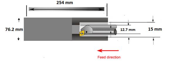
Figure MR 8.9. Dimensions of the Work piece
The machining conditions and the cutting parameters are listed in Table MR8.7.
Table MR8.7. Cutting Parameters for Example Case
Cutting Conditions |
|
Final hole Diameter (Df) |
15 mm |
Cutting Speed (V), Table MR8.2 |
40 m/min |
Feed (f), Table MR8.2 |
0.5 mm/rev |
Spindle Speed (N) = V/πD |
850 rpm |
Feed rate (fr) = f*N |
425 mm/min |
Initial hole diameter (Di) |
12.7 mm |
Volume removal rate |
21,255 mm3/min |
Depth of hole (d) |
50 mm |
Rapid Horizontal Traverse rate, HTR, (horizontal, X,Y) (m/min) |
30 |
Rapid Vertical Traverse rate, VTR (vertical, Z) (m/min) |
24 |
Before boring holes on the work piece in a CNC machine, it is important to set the co-ordinate axes of the machine with respect to the work piece. The left bottom hole on the top surface is considered as the origin (reference point). All dimensions are considered with reference to the origin. The direction along the length and breadth are taken as positive X and Y axis respectively. The vertical plane perpendicular to the work piece is considered as the Z-axis. During the boring process the tool is considered to be at an offset of 10 mm above the work piece. Every time while boring a hole the tool comes down from a height of 10 mm to the approach distance, 5 mm, from the workpiece. Because the end of the cut is a flat surface there is no overtravel. It goes back to the home position at transverse speed/. The feeds and speed are stated in Table MR8.7.
The total processing time can be divided into the 3 sub groups of basic time, idle time, and boring time.
Boring Time:
The time for boring or enlarging a through hole is determined by
tboring = d/f*N = d/fr (min)
Where d is the depth of the hole in mm, fr is the feed in mm/min.
d = depth of the hole = 50 mm
Time to bore a hole will be,
tboring = (50)/ 425
= 0.118 min/hole = 7 sec/hole
Machining Power for each hole,
pboring = VRR * Specific cutting energy
VRR from Table MR8.7 = 21,255 mm3/min and specific cutting energy, Up, from Table MR8.2 = 2.98 W/mm3/sec
pboring = (21,255/60) *2.98 = 1.06 kW
Tip Energy required per hole is eboring = pboring * tboring = 1.06 * 7 = 7.39 kJ/hole
Handling Time:
Time required for the cutter to move from home position to approach point (10mm) is essentially boring in air. The air time of the rapid traverse speed to approach is
ta1 = 10/ (traverse speed)
ta1 = 10/ 24000 mm/min
= 0.0004 min = 0.0025sec (neglect)
After reaching the approach distance 5 mm from the workpiece it reaches the workpiece at feed rate, fr (425 mm/min. When not cutting the workpiece, the approach distance,
(Approach)/fr
ta2 = (15)/425 mm/min
= 0.035 min = 2 sec
Retract time ta3 = (50 + 5)/24000 = 0.14 sec
Idle power of the machine can be calculated based on the individual power specifications of the machine.
Pidle = Pspindle + Pcoolant + Paxis
The assumed values are
Pcoolant = 1 kW (~1.5 hp); Pspindle = 4 kW (~5 hp); Paxis = 5 kW (~7 hp)
(These assumed values are from the CNC manufacturing companies, see Appendix 1)
To convert a horse power rating (HP) to Watts (W) simply multiply the horsepower rating by 746
Idle power for the process is
Pidle = Pspindle + Pcoolant + Paxis
=4 + 1 + 5
= 10 kW
Total Idle time for cut t idle = ta + tboring = 2 + 0.14 + 7
= 9.14 sec
Total Energy during the idle process is,
eidle = Pspindle * tidle + Pcoolant* tidle + Paxis*tidle
= 10*9.14
= 91.4 kJ/hole
Load/unload Time:
The total basic time can be determined based on the following assumptions for this example:
Therefore, basic processes time for this study is,
Tb = loading time + cleaning time + unloading time
= 25 + 25 + 25
= 75 sec
Basic power of the machine can be assumed as the 25% of the machine maximum in the manufacturer specifications. Therefore the power consumed during the basic process is,
Pbasic = 7.5 kW
Energy consumed during this process is,
Ebasic = Pbasic * ttotal
The basic time for the process can be taken as the sum of idle time (which contains machining time) and load/unload times, i.e.
Tbasic = Tb + tidle
= 75 + 9.14
= 84.14 sec
ebasic = 7.5* 84.14 = 631 kJ per hole
Total Energy required for turning can be determined as,
eprocess = eboring +eidle + ebasic
=7.39 + 91.4 + 631
= 729.84 kJ/ hole
Power required for machine utilization during boring is,
Pmtotal = eprocess / ttotal
= 729.84/84.14 = 8.67 kW.
Volume of the material removed for a hole = ![]() [mm3]
[mm3]
= 2,500 mm3
Chip mass (ms) = Vremoval * ρ [kg]
ms = 2,500 * 8,000 * 10-9
= 0.02 g/hole
From (Andres et al., 2008) a single CNC machine using cutting fluid required an individual pump to circulate the fluid from a 55 gallon (208L) tank to the cutting zone. The 208L/machine is recycled within process until it is disposed of after two weeks. Assuming cutting fluid is used 204 hr/ 2 weeks, then the cutting fluid loss is 208L/ (204*60) per minute, which is 0.017 L/min or about 17 g/min. The coolant is about 96wt%, so at 96wt% water, the coolant oil loss is 4wt% or 0.68 g cutting oil/min (= 0.042 g/sec).
Boring time per hole tm = 7 sec
Mass loss of the coolant = 0.68*7/60 = 0.079g cutting oil/hole
This report presented the models, approaches, and measures used to represent the environmental life cycle of boring unit operations referred to as the unit process life cycle inventory. The five major environmental-based results are energy consumption, metal chips removed, cutting fluid, lubricant oil, and cutting tool. With only the following information the unit process life cycle energy for boring can be estimated.
The life cycle of boring is based on a typical high production scenario (on a CNC Boring machine) to reflect industrial manufacturing practices.
The methodology that has been followed for collecting technical information on CNC machines has been largely based in the following:
The documentation of the CNC machine and the technical assistances collected from the manufacturing companies through internet. Several interviews with the service personnel of the different CNC manufacturing companies have been carried out. After collecting the information from the different companies it has been put together in the relevant document that describes the different approaches the different companies have regarding the technical information on the CNC machines. Telephone conversations allowed us to learn more about basic power and idle power. Companies that involved in our telephone conversations are Bridge port, Fadal, Hass and Jeenxi. These companies’ manufactures different sizes of CNC machines, but this report shows the lower, mid and highest level of sizes. For our case study we picked machine at the highest-level.
Specifications |
JEENXI TECHNOLOGY |
||
Model Number |
JHV – 850 |
JHV – 1020 |
JHV – 1500 |
Spindle Speed |
8000 rpm |
8000 rpm |
8000 rpm |
Spindle Drive |
Belt/Direct type |
Belt/Direct |
Belt/Direct type |
Spindle Motor |
5.5/7.5 kw |
7.5/11 kw |
7.5/ 11 kw |
Rapid Traverse (X,Y) |
30 m/min |
30 m/min |
30 m/min |
Rapid Traverse (Z) |
20 m/min |
20 m/min |
24 m/min |
Cutting Feed rate |
1 – 15000 mm/min |
1 – 15000 mm/min |
1 – 15000 mm/min |
3 Axes motor output(X,Y,Z) |
1.8/ 1.8/ 2.5 |
1.8/ 1.8/ 2.5 |
4.0/ 4.0/ 7.0 |
Power Consumption |
20 KVA |
20KVA |
40 KVA |
|
|||
Specifications |
HAAS |
||
Model Number |
VF- 7 |
VM - 2 |
MDC |
Spindle Speed |
7500 rpm |
12,000 rpm |
7,500 rpm |
Spindle Drive |
Belt/Direct type |
Inline direct drive |
Direct speed belt drive |
Max Torque |
75 ft-lb@1400 |
75 ft-lb@1400 |
75 ft-lb@1400 |
With Gearbox |
250 ft-lb@ 450 |
- |
- |
Spindle motor max rating |
20 hp |
30 hp |
20 hp |
Axis Motor max thrust |
3400 lb |
3,400 lb |
2,500 lb |
Rapids on X-axis |
600 ipm |
710 ipm |
1,000 ipm |
Rapid on Y & Z Axes |
600 ipm |
710 ipm |
1,000 ipm |
Max Cutting |
500ipm |
500 ipm |
833 ipm |
Power Consumption(min) |
200 – 250 VAC |
200 – 250 VAC |
200 – 250 VAC |
|
|||
Specifications |
KAFO |
||
Model Number |
VMC – 850 |
VMC – 137 |
VMC - 21100 |
Spindle speed (Belt) |
8000 rpm |
8,000/10,000 rpm |
6000/8000 rpm |
Spindle speed (Gear) |
4000/7000 rpm |
4000/7000 rpm |
4000/7000 rpm |
Rapid Traverse (X, Y) |
590.55 ipm |
787.4 ipm |
393.7 ipm |
Rapid Traverse (Z) |
472.44 ipm |
787.40 ipm |
393.7 ipm |
Cutting feed rate |
236.22 ipm |
393.7 ipm |
393.7 ipm |
Spindle drive motor |
7.5/ 10 hp |
15/ 20 hp |
15/20 hp |
X,Y,Z axis drive motor |
a12, a12, a12 |
a22, a22, a30 |
a30, a30, a30 |
Power consumption |
20 KVA |
25 KVA |
35 KVA |
|
|||
Specifications |
BRIDGE PORT |
||
Model Number |
XR 760 |
XR 1270 HP |
XR 1500 HPD |
Spindle Speed(Belted) |
9000/15000 rpm |
- |
- |
Fanuc Motor Power |
25/25 hp |
- |
- |
Heidenhain Motor Power |
28/28 hp |
- |
- |
Spindle Speed(Directly coupled) |
15000 rpm |
15000 rpm |
375 – 7500 rpm (Gear Box) |
Fanuc Motor Power |
30 hp |
40 hp |
40 hp |
Heidenhain Motor Power |
33 hp |
34 hp |
40 hp |
Rapid Traverse (X,Y) |
1692 ipm |
1417 ipm |
1417 ipm |
Rapid Traverse (Z) |
1417 ipm |
1417 ipm |
1417 ipm |
Cutting Feed rate |
787 ipm |
787 ipm |
787 ipm |
Power |
30 KVA |
40 KVA |
40 KVA |
|
|||
Specifications |
FADAL |
||
Model Number |
VMC 4020 |
VMC 6030 |
VMC 6535 HTX |
Spindle Speed |
10 - 10,000 rpm |
10 - 10,000 rpm |
6000 rpm |
Spindle Drive |
Automatic Mechanical Vector Drive |
Automatic Mechanical Vector Drive |
Automatic Electric Vector Drive |
Rapid Traverse (X,Y) |
900 ipm |
400 ipm |
900 ipm |
Rapid Traverse (Z) |
700 ipm |
400 ipm |
700 ipm |
Cutting Feed rate |
600 ipm |
400 ipm |
600 ipm |
Motor Power |
10 hp |
14.7 hp |
29.5 hp |
Air Pressure Required |
80 – 120 psi |
80 – 120 psi |
80 – 100 psi |
|
|||
Specifications |
TTC |
||
Model Number |
TTC-630 |
TMC 500 |
XR 1500 HPD |
Spindle Speed(Belted) |
4000 rpm |
6000 |
- |
Spindle Motor Power |
15/20 KW |
5/7 KW |
- |
X Axis Motor Power |
2.8 KW |
- |
- |
Z Axis Motor Power |
2.8 KW |
15000 rpm |
375 – 7500 rpm (Gear Box) |
Coolant Pump Motor Power |
1 KW |
40 hp |
40 hp |
ATC Motor Power |
12.6 KW |
34 hp |
40 hp |
Rapid Traverse (X,Y) |
197 mm/min |
1417 ipm |
1417 ipm |
Rapid Traverse (Z) |
630 mm/min |
1417 ipm |
1417 ipm |
Total Driving Power |
40 KW |
787 ipm |
787 ipm |
Hydraulic Pump |
1.1 KW |
40 KVA |
40 KVA |
Source: http://cratel.wichita.edu/uplci/wp-content/uploads/2010/06/MR8_Boring_Process_5-02-10.doc
Web site to visit: http://cratel.wichita.edu
Author of the text: indicated on the source document of the above text
If you are the author of the text above and you not agree to share your knowledge for teaching, research, scholarship (for fair use as indicated in the United States copyrigh low) please send us an e-mail and we will remove your text quickly. Fair use is a limitation and exception to the exclusive right granted by copyright law to the author of a creative work. In United States copyright law, fair use is a doctrine that permits limited use of copyrighted material without acquiring permission from the rights holders. Examples of fair use include commentary, search engines, criticism, news reporting, research, teaching, library archiving and scholarship. It provides for the legal, unlicensed citation or incorporation of copyrighted material in another author's work under a four-factor balancing test. (source: http://en.wikipedia.org/wiki/Fair_use)
The information of medicine and health contained in the site are of a general nature and purpose which is purely informative and for this reason may not replace in any case, the council of a doctor or a qualified entity legally to the profession.
The texts are the property of their respective authors and we thank them for giving us the opportunity to share for free to students, teachers and users of the Web their texts will used only for illustrative educational and scientific purposes only.
All the information in our site are given for nonprofit educational purposes